 Embedded HandbookApps
102. Weight: load cell and HX711
A load cell is a metal bar with strain gauges glued to it and wired into a bridge. Under load the bar bends slightly, and the bridge outputs millivolts — per volt of its supply. Such a signal is beyond the microcontroller's built-in ADC, so an HX711 is used: a 24-bit ADC with an amplifier, made specifically for bridges, with its own two-wire interface. It has four places where a scale starts to lie: the sign of the 24-bit number, a gain that takes effect late, the 60 µs limit on the clock wire, and calibration.
Internal ADC — section 14, critical sections — section 30, connecting modules — section 95.
Terms used in the documentation
Term Meaning load cell a bar with strain gauges glued to it strain gauge a resistor whose value changes with strain Wheatstone bridge four resistors in a bridge excitation voltage the bridge supply voltage sensitivity, mV/V sensitivity: millivolts per volt of supply at full load tare zeroing the scale span calibration calibration with a known weight programmable gain amplifier (PGA) an amplifier with a selectable gain two's complement the usual encoding of signed integers power-down sleep mode
102.1 The bridge and its millivolts
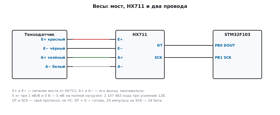
The bridge signal is the sensitivity multiplied by the supply and by the fraction of the load. A 5 kg cell with a sensitivity of 1 mV/V at a 5 V supply outputs only 5 mV at full load. The 12-bit STM32 ADC with a 3.3 V reference resolves 0.806 mV — the whole signal would fit into a little over six codes. The HX711 at gain 128 measures ±19.531 mV with 24 bits: one code is 2.328 nV, 5 mV is 2147483 codes, that is 429.5 codes per gram. The input range is ±0.5 · AVDD / gain, and ±19.531 mV comes out at AVDD = 5 V. On ready-made modules AVDD is usually about 4.3 V; the bridge is powered from the same voltage, so the codes per gram stay the same, and the millivolts are fewer.
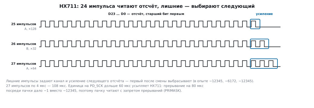
The channel and gain are selected by the number of pulses after the 24 bits:
| Pulses after 24 bits | Channel | Gain | Input |
|---|---|---|---|
| 25 | A | 128 | ±19.531 mV |
| 26 | B | 32 | ±78.125 mV |
| 27 | A | 64 | ±39.062 mV |
102.2 Two wires, but not I²C
The HX711 has no addresses and no acknowledgements. The DOUT pin goes low when a sample is ready; the master applies 24 pulses to PD_SCK and after each edge reads the next bit, most significant first; another 1–3 pulses select the channel and gain. There are 10 or 80 samples per second, depending on the RATE pin.
int hx711_read(unsigned extra, int32_t *value)
{
    unsigned guard = 0;
    while (hx_dout()) {
        if (++guard > 200000u)
            return 0;                   /* готовности нет: датчика нет или он спит */
        hx_wait_us(1);
    }
    uint32_t raw = 0;
    HX_LOCK();
    for (unsigned i = 0; i < 24u + extra; i++) {
        hx_sck(1);
        hx_wait_us(2);                  /* единица на SCK — не дольше 60 мкс, иначе HX711 уснёт */
        if (i < 24u)
            raw = raw << 1 | (uint32_t)hx_dout();
        hx_sck(0);
        hx_wait_us(2);
    }
    HX_UNLOCK();
    *value = hx711_sign(raw);
    return 1;
}
hx_sck, hx_dout and hx_wait_us are three platform functions: on the board they are
GPIO and a 1 MHz timer, on the PC — a model of the chip that responds
to pulses the same way the HX711 does.
102.3 The sign of 24 bits
A sample is a 24-bit number in two's complement, and it has to be moved into a 32-bit variable with sign extension:
int32_t hx711_sign(uint32_t raw)
{
    return (raw & 0x800000u) ? (int32_t)(raw | 0xFF000000u) : (int32_t)raw;
}
0xFFFFFF is −1, 0x800000 is −8388608, 0x7FFFFF is 8388607. Without sign extension the same −1 turns into 16777215 codes — at 429.5 codes per gram that is 39 kg on an empty scale.
102.4 The gain is for the next sample
The extra pulses select the gain not for the sample being read now, but for the next one. Model: the code at gain 128 is −12345. A read asking for "×64" still returns −12345, the next one is −6172, already at ×64, and after asking to go back to ×128 the next sample is −12345 again. So after a change of gain or channel the first sample is from the old setting, and it is thrown away.
102.5 Sixty microseconds
If PD_SCK stays high for longer than 60 µs, the HX711 goes to sleep. In a program this happens by itself: an interrupt arrives while SCK is high, and the falling edge is postponed for the duration of the handler. Model: an "interrupt" of 80 µs on the tenth pulse — and instead of −12345 the read gives −1, and the chip is asleep. So the pulse burst is not interrupted:
#define HX_LOCK()   uint32_t hx_pm = __get_PRIMASK(); __disable_irq()
#define HX_UNLOCK() __set_PRIMASK(hx_pm)
With interrupts disabled, the same "interrupt" waits for the end of the burst, and the sample is correct:
−12345. The burst is short — 27 pulses of 4 µs, 108 µs — and for most
devices such a pause in interrupts goes unnoticed. PRIMASK is saved
and restored rather than interrupts simply re-enabled: otherwise the function would enable
them even where the caller had disabled them.
102.6 Tare and calibration
The bridge code with no load is not zero, and every cell has its own scale. So a scale is set up twice: empty — that is the tare, and with a known weight — the scale factor:
int hx711_average(unsigned n, int32_t *avg)
{
    int64_t sum = 0;
    for (unsigned i = 0; i < n; i++) {
        int32_t v;
        if (!hx711_read(HX_A128, &v))
            return 0;
        sum += v;
    }
    *avg = (int32_t)(sum / (int64_t)n);
    return 1;
}

void scale_calibrate(scale_t *s, int32_t tare, int32_t loaded, int32_t mass_g)
{
    s->offset = tare;
    s->per_kg = (int32_t)((int64_t)(loaded - tare) * 1000 / mass_g);
}

int32_t scale_dg(const scale_t *s, int32_t reading)
{
    return (int32_t)((int64_t)(reading - s->offset) * 10000 / s->per_kg);
}
Scale model: bridge offset 84000 codes, 429.5 codes per gram, noise ±200 codes, that is ±0.47 g per sample. Tare over 16 samples is 83973, with a 1000 g weight it is 513528, the scale factor is 429555 codes per kilogram. A 250 g weight reads as 249.9 g on the average of 16 samples and 250.1 g on a single one. Averaging 16 samples cuts the noise by a factor of four. The tare drifts with temperature, so the scale is zeroed before weighing, not once at assembly.
102.7 Pitfalls
The empty scale shows 39 kg. A 24-bit code without sign extension: −1 became 16777215.
After a gain change the first sample is "wrong". The gain takes effect from the next sample. Throw the first one away.
Occasionally — wild values and a pause. An interrupt stretched the high level on SCK beyond 60 µs, and the HX711 went to sleep. Disable interrupts for the pulse burst.
After stopping in the debugger the scale is silent. The program stopped while SCK was high — the chip is asleep. Pull SCK low and wait for ready.
The weight creeps. The tare drifts with temperature. Zero before weighing, let the cell warm up.
102.8 Summary
- A load cell bridge gives millivolts: 5 kg at 1 mV/V and 5 V is 5 mV; the built-in 12-bit ADC would see six codes, the HX711 at ×128 — 2147483, 429.5 codes per gram.
- The HX711 has its own protocol: DOUT = 0 means ready, 24 pulses, most significant bit first; 1–3 extra pulses set the gain of the next sample.
- A sample is 24 bits in two's complement: extend the sign.
- SCK high for longer than 60 µs means sleep: do not interrupt the pulse burst,
save and restore
PRIMASK. - A scale means tare and calibration with a known weight; averaging 16 samples cuts the noise by a factor of four.
Next: section 103 "Light and gas: photoresistor, BH1750, MQ" — a divider with a photoresistor, a digital light sensor and gas sensors with a heater.