 Embedded HandbookApps
101а. Current and power monitor INA226: 16 bits, calibration register, averaging, threshold alert and energy counting
Section 101 covers the INA219: a shunt, its own ADC, a calibration
number, and current and power over I2C. The INA226 is the next step in
the same family: a four times finer shunt step, its own averaging inside
the chip and an ALERT pin that raises the alarm on an overload by
itself. Here: how it differs from the INA219, how to connect it to the
F103 and choose a shunt, how to compute CAL and convert the registers
with integers, what averaging and conversion time give, how the alarm
works, how to count milliamp-hours and watt-hours and what to do with
current in both directions.
Sources: the ina226 driver from Zephyr 4.4.2 (drivers/sensor/ti/ina2xx/ina226.c,
ina226.h, include/zephyr/dt-bindings/sensor/ina226.h,
dts/bindings/sensor/ti,ina226.yaml): the register numbers, 2.5 µV per
shunt unit, 1.25 mV per bus unit, the power step of 25 current steps, the
CAL formula, the Config fields, the times 140…8244 µs and the AVG
count 1…1024, the values after reset, the manufacturer code 0x5449. The
Mask/Enable bits come from the description of the related INA230 in the
same tree (include/zephyr/dt-bindings/sensor/ina230.h). RM0008 (DocID13902
Rev 17): the pin mode table, p. 160; AFIO_EXTICR2, p. 190;
EXTI_FTSR, p. 211; master reception of two bytes, p. 764; I2C_CCR,
p. 783–784; I2C_TRISE, p. 784. DocID13587 Rev 17: PB6 is I2C1_SCL,
PB7 is I2C1_SDA, both FT, p. 32. The project has no document on the INA226:
the addresses set by pins A1 and A0, the bus voltage limit, bit 14 of Config,
the internal calculation with its rounding and the behaviour of the flags and of ALERT come from
the manufacturer's documentation, are built into the model and were not
checked against the chip. All numbers come from a run of the driver _verify/ina101b/ina226.c on a
computer (gcc 12.2.0) with our own model of the INA226 as an I2C slave in
Python 3.11; the firmware is built by armclang 6.24 for the Cortex-M3.
What it is called in the documentation
Original Meaning current/power monitor shunt, ADC and calculation in one chip shunt voltage, bus voltage the voltage across the shunt; the bus voltage relative to ground calibration register (CAL) links the shunt code to current Current_LSB the current step — the weight of one unit of Currentaveraging (AVG) how many conversions are summed into one result conversion time (VBUSCT, VSHCT) the time of one bus and one shunt conversion Mask/Enable register what goes to ALERT, and the flagsalert limit the alarm threshold shunt over-voltage (SOL) shunt above the threshold — current overload conversion ready (CNVR, CVRF) "result ready": enable on ALERTand the flaglatch enable (LEN) latch: hold the alarm until it is read math overflow (OVF) overflow of the current or power calculation Kelvin connection separate wires from the shunt pads coulomb counting the integral of current over time
101а.1 How the INA226 differs from the INA219
| INA219 (section 101) | INA226 | |
|---|---|---|
| shunt: unit | 10 µV | 2.5 µV |
| shunt: range | ±320 mV at the default gain | ±81.92 mV, only one |
| bus: unit | 4 mV | 1.25 mV |
| shunt and current registers | 12 bits in the setting after reset | 16 bits signed |
| calibration | CAL = 0.04096 / (I_LSB · R) | CAL = 0.00512 / (Current_LSB · R) |
| power step | 20 current steps | 25 current steps |
The shunt range is 32768 units of 2.5 µV, that is ±81.92 mV: 3.9 times
narrower than ±320 mV on the INA219, but the unit is four times finer. The INA226 sets its own averaging with the AVG field — from 1
to 1024 conversions of 140…8244 µs, and the ALERT pin with a threshold and a
latch raises the alarm without polling. There is no gain field in
Config on the INA226 — only AVG, VBUSCT, VSHCT and MODE, so the shunt
is chosen for this single range (101а.2). The bus voltage limit of 36 V
comes from the manufacturer's documentation, it is not on disk: not verified.
Inside, the chip calculates the same way as the INA219, only with other numbers:
Current = Shunt × CAL / 2048, Power = Current × Bus / 20000.
This follows from the Zephyr weights: 0.00512 / (2.5 µV × 2048) = 1, that is
the current code is the shunt current in Current_LSB steps, and 1.25 mV / 25 = 1/20000.
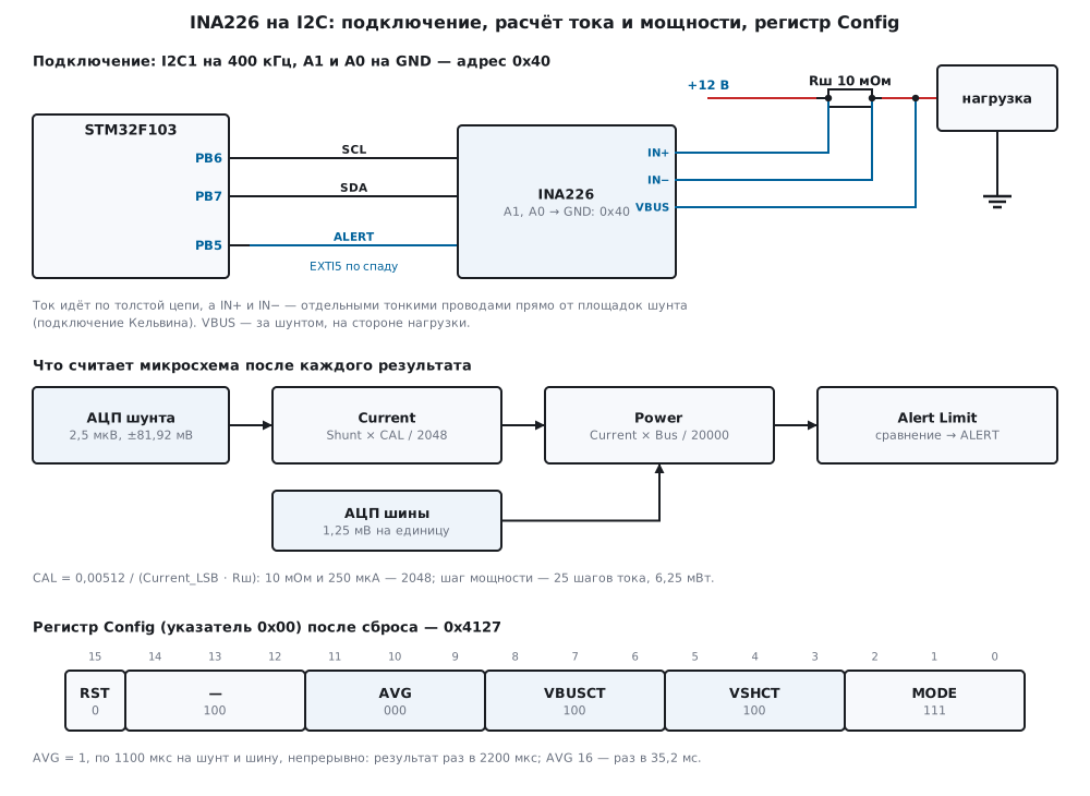
101а.2 Connecting to the F103 and choosing a shunt
| INA226 pin | Where | Purpose |
|---|---|---|
| SCL, SDA | PB6, PB7 | I2C1 |
| ALERT | PB5 | alarm or "ready"; EXTI5 on the falling edge |
| A1, A0 | GND | address 0x40 |
| VS, GND | 3.3 V and ground | common ground with the F103 |
| IN+, IN− | shunt pads | voltage across the shunt |
| VBUS | bus on the load side | voltage for power |
I2C1 is as in 15б.2: 400 kHz, CCR = F/S | 30, TRISE = 11; PB6 and PB7 are
FT (DocID13587, p. 32), PB5 is an input with pull-up (code 1000, p. 160).
ALERT goes to EXTI5: AFIO_EXTICR2 — port B (p. 190), the falling edge is enabled by
EXTI_FTSR (p. 211). Reading a register is a pointer write, a repeated
start and two bytes, high byte first, as in 17.4; at 400 kHz in the model that is
120 µs, and the four registers of ina_measure take 480 µs.
The address is set by two pins, each with four positions — 16 addresses:
| A1 \ A0 | GND | VS | SDA | SCL |
|---|---|---|---|---|
| GND | 0x40 | 0x41 | 0x42 | 0x43 |
| VS | 0x44 | 0x45 | 0x46 | 0x47 |
| SDA | 0x48 | 0x49 | 0x4A | 0x4B |
| SCL | 0x4C | 0x4D | 0x4E | 0x4F |
The shunt. The full-scale current is 81.92 mV / R, the dissipation in it is I² · R. The current step is taken no smaller than Imax / 32768 and rounded up to a "round" value:
| Shunt | Full scale | Dissipation at it | Imax | Current_LSB | CAL | Shunt unit in current |
|---|---|---|---|---|---|---|
| 100 mOhm | 0.819 A | 0.067 W | 0.8 A | 25 µA | 2048 | 0.025 mA |
| 10 mOhm | 8.192 A | 0.671 W | 8 A | 250 µA | 2048 | 0.25 mA |
| 5 mOhm | 16.384 A | 1.342 W | 15 A | 500 µA | 2048 | 0.5 mA |
| 2 mOhm | 40.96 A | 3.355 W | 40 A | 2000 µA | 1280 | 1.25 mA |
| 1 mOhm | 81.92 A | 6.711 W | 80 A | 2500 µA | 2048 | 2.5 mA |
A smaller shunt heats less, but the unit in current is coarser: at 1 mOhm the shunt unit is already 2.5 mA. For an 8 A instrument 10 mOhm fits: 0.671 W at full scale, a 1 W resistor.
101а.3 Calibration: CAL, the current step and converting the registers
CAL = 0.00512 / (Current_LSB · R). In the driver the current step is in nanoamps, the shunt in micro-ohms, and the formula becomes integer: 5.12 · 10¹² / (lsb · R) with rounding. Zephyr calculates the same way, only in microamps:
/* шаг тока: не меньше Imax / 32768 и «круглый» — 1, 2, 2,5 или 5 × 10^n нА (от 10 нА) */
uint32_t ina_lsb_na(uint32_t imax_ma)
{
    static const uint32_t nice[4] = {10, 20, 25, 50};
    uint32_t need = (uint32_t)(((uint64_t)imax_ma * 1000000u + 32767u) / 32768u);   /* нА, вверх */
    for (uint32_t dec = 1; dec <= 10000000u; dec *= 10u)
        for (uint32_t i = 0; i < 4u; i++)
            if (nice[i] * dec >= need)
                return nice[i] * dec;
    return 0;
}

/* CAL = 0,00512 / (Current_LSB · Rshunt); в нА и мкОм — 5,12 · 10^12 / (lsb · R), с округлением */
uint32_t ina_cal(uint32_t lsb_na, uint32_t rshunt_uohm)
{
    uint64_t den = (uint64_t)lsb_na * rshunt_uohm;
    uint64_t cal = (5120000000000ull + den / 2u) / den;
    return cal == 0u || cal > 0x7FFFu ? 0u : (uint32_t)cal;   /* 0 — такой CAL записать нельзя */
}
Why a "round" step matters shows in the rounding error of CAL. In the model a
known current flowed through the shunt and the driver read it:
| Shunt | Current_LSB | Exact CAL | CAL | CAL error | Current | Read |
|---|---|---|---|---|---|---|
| 100 mOhm | 25 µA | 2048 | 2048 | 0 | 0.5 A | 500 000 µA |
| 100 mOhm | 24.414 µA | 2097.157 | 2097 | −75 ppm | 0.5 A | 499 949 µA |
| 100 mOhm | 1000 µA | 51.2 | 51 | −3906 ppm | 0.5 A | 498 000 µA |
| 10 mOhm | 250 µA | 2048 | 2048 | 0 | 5 A | 5 000 000 µA |
| 3 mOhm | 500 µA | 3413.333 | 3413 | −98 ppm | 10 A | 9 999 000 µA |
A step of exactly Imax / 32768 (24.414 µA) does not make CAL an integer and gives
−0.01 %. A coarse step (1 mA at 100 mOhm) makes CAL small — 51 instead of
51.2, and the current is off by −0.4 %. And a step of 0.1 µA at 1 mOhm needs CAL =
51 200 000 — it does not fit the register, and ina_cal returns 0.
Initialisation: reset with bit 15 of Config, a check of the manufacturer code,
Config, CAL and reading CAL back — 5 transfers, 525 µs:
int ina_init(ina_t *d, uint8_t addr7, uint32_t lsb_na, uint32_t rshunt_uohm, uint16_t cfg)
{
    uint16_t id, back;
    int rc;
    d->addr = addr7;
    d->xfers = d->errors = 0;
    d->lsb_na = lsb_na;
    d->rshunt_uohm = rshunt_uohm;
    d->cfg = cfg;
    d->cal = (uint16_t)ina_cal(lsb_na, rshunt_uohm);
    if (d->cal == 0u)
        return INA_E_RANGE;                             /* шаг тока и шунт не дают допустимого CAL */
    if ((rc = ina_write(d, INA_CONFIG, INA_CFG_RST)) != INA_OK)
        return rc;
    if ((rc = ina_read(d, INA_MFG_ID, &id)) != INA_OK)
        return rc;
    if (id != INA_MFG_TI)
        return INA_E_ID;
    if ((rc = ina_write(d, INA_CONFIG, cfg)) != INA_OK || (rc = ina_write(d, INA_CAL, d->cal)) != INA_OK
        || (rc = ina_read(d, INA_CAL, &back)) != INA_OK)
        return rc;
    return back == d->cal ? INA_OK : INA_E_CAL;
}
After reset in the model Config = 0x4127, CAL = 0x0000, Mask/Enable
and Alert Limit are 0, the manufacturer code is 0x5449. While CAL = 0, current
and power are zeros: at 0.5 A through 10 mOhm the shunt showed 5 000 000 nV, while
Current and Power were 0.
Integer conversion. Current is the signed code × the step, power is the unsigned code × 25 steps; the products are 64-bit:
int32_t ina_current_ua(int16_t raw, uint32_t lsb_na)
{
    return (int32_t)((int64_t)raw * lsb_na / 1000);
}

uint32_t ina_power_uw(uint16_t raw, uint32_t lsb_na)
{
    return (uint32_t)((uint64_t)raw * 25u * lsb_na / 1000u);   /* шаг мощности — 25 шагов тока */
}
Shunt 10 mOhm, step 250 µA, CAL = 2048, bus 12 V. Current 2.5 A: Shunt =
0x2710 (10000 units, 25 mV), Bus = 0x2580 (9600), Current =
10000 × 2048 / 2048 = 10000, Power = 10000 × 9600 / 20000 = 4800
(0x12C0). The driver: 2 500 000 µA, 30 000 000 µW, 12 000 000 µV. Current
−1.2 A: Shunt and Current = 0xED40 (−4800), while Power = 0x0900 (2304) —
14 400 000 µW, unsigned (101а.6).
101а.4 Averaging and conversion time
A result is AVG pairs of conversions "shunt, then bus", each lasting VSHCT and VBUSCT. In continuous mode a new result is ready every AVG × (VBUSCT + VSHCT):
/* время одного результата в непрерывном режиме «шунт и шина»: AVG × (VBUSCT + VSHCT) */
uint32_t ina_conv_us(uint16_t cfg)
{
    return avg_n[cfg >> 9 & 7u] * (uint32_t)(ct_us[cfg >> 6 & 7u] + ct_us[cfg >> 3 & 7u]);
}
After reset it is AVG 1 and 1100 µs each: a result every 2200 µs. The noise in the model is set like this: 7.5 µV on the shunt at 140 µs, falling as 1/√t — this is an assumption, not data from a document. Current 0.5 A through 10 mOhm, step 250 µA, results in a row by "ready":
| AVG | Time | Config |
Result every | Current RMS | Distinct codes | Spread |
|---|---|---|---|---|---|---|
| 1 | 140 µs | 0x4007 | 280 µs | 0.774 mA | 16 | 3.75 mA |
| 1 | 1100 µs | 0x4127 | 2200 µs | 0.29 mA | 7 | 1.5 mA |
| 4 | 1100 µs | 0x4327 | 8800 µs | 0.129 mA | 3 | 0.5 mA |
| 16 | 1100 µs | 0x4527 | 35 200 µs | 0.059 mA | 3 | 0.5 mA |
| 64 | 1100 µs | 0x4727 | 140 800 µs | 0 | 1 | 0 |
| 1024 | 8244 µs | 0x4FFF | 16 883 712 µs | 0 | 1 | 0 |
With AVG 64 the model noise is below one shunt unit, and all 200 results are identical — there is nothing more to sum (14а.6). But the result becomes slow: with AVG 1024 and 8244 µs it is almost 17 s. The price is response: long averaging smears a short overload (101а.5), and instantaneous current values are lost when counting energy (101а.6).
101а.5 The ALERT alarm: overload, power, "ready" and the latch
The threshold is written to Alert Limit in units of the register it is
compared with, and Mask/Enable selects one function: SOL — shunt above the
threshold, SUL — below, BOL, BUL — bus, POL — power above, and
CNVR — "ready" — can be added to it. Bit LEN is the latch, APOL is the
pin polarity.
/* порог по току — в единицах регистра шунта: I · R / 2,5 мкВ */
uint16_t ina_shunt_limit(int32_t current_ma, uint32_t rshunt_uohm)
{
    int64_t x = (int64_t)current_ma * rshunt_uohm;      /* мА · мкОм = 10^-9 В */
    int64_t code = (x >= 0 ? x + 1250 : x - 1250) / 2500;
    return (uint16_t)(int16_t)(code > 32767 ? 32767 : code < -32768 ? -32768 : code);
}
An overload of 3 A on 10 mOhm is 30 mV, Alert Limit = 12000 (0x2EE0);
power of 40 W at a 250 µA step is 6400 (0x1900). In the model the current is 1 A, at the
200th ms it jumps to 4 A for 50 ms:
| AVG and time | Result every | SOL 3 A fired |
After |
|---|---|---|---|
| 1, 140 µs | 280 µs | yes | 0.507 ms |
| 16, 1100 µs | 35.2 ms | yes | 46.708 ms |
| 64, 1100 µs | 140.8 ms | no | — |
| 128, 1100 µs | 281.6 ms | no | — |
What is compared is the result, not the instantaneous current: with AVG 64, 50 ms at 4 A are averaged with 1 A to no more than 2.07 A — below the threshold, and there is no alarm. A 500 ms pulse with AVG 128 did raise the alarm, but after 363.507 ms. For protection a short averaging is used, for readings a long one; with one chip you have to choose.
Without the latch the pin went back up as soon as the current fell. With LEN it
stayed low after the pulse too; reading Mask/Enable returned 0x8019
(SOL, AFF, CVRF, LEN) and released the pin. POL at 40 W at
12 V fired the same way, after 46.708 ms. In the firmware the falling-edge interrupt
switches the load off at once:
/* ALERT: спад на PB5 — перегрузка; нагрузку выключить сразу, в прерывании */
void EXTI9_5_IRQHandler(void)
{
    EXTI->PR = 1u << 5;
    GPIOA->BRR = 1u << 0;
    alert = 1;
}
"Ready". With CNVR the pin goes low at the end of every result and
stays there until Mask/Enable is read. In 1 s with AVG 16 the model gave
29 results: with Mask/Enable read after each one — 29 falling edges, without
reading — 1.
101а.6 Energy counting and current in both directions
Milliamp-hours are the integral of current, watt-hours the integral of power (coulomb counting, 173б.5). The driver accumulates µA·µs in 64 bits — as rectangles: the last result × time:
/* прямоугольник: последний результат × время с прошлого вызова; знак мощности — по знаку тока */
void ina_energy_add(ina_energy_t *e, const ina_meas_t *m, uint32_t dt_us)
{
    e->ua_us += (int64_t)m->current_ua * dt_us;
    if (m->current_ua >= 0)
        e->uw_us_in += (int64_t)m->power_uw * dt_us;
    else
        e->uw_us_out += (int64_t)m->power_uw * dt_us;
}
At 2 A such a counter overflows in 53.4 days, while a 32-bit one in µA·ms overflows in 1.074 s. In the model the load is 0.3 A plus pulses of another 1.7 A for 20 % of the time with a period of 37 ms — 0.64 A on average, bus 12 V, shunt 10 mOhm, 30 s:
| How it was counted | Exact | Counted | Error |
|---|---|---|---|
| timer 100 ms, AVG 1, 140 µs | 5333 µA·h | 5379 µA·h | +0.86 % |
| timer 100 ms, AVG 16, 1100 µs | 5334 µA·h | 5336 µA·h | +0.04 % |
| timer 100 ms, AVG 64, 1100 µs | 5334 µA·h | 5332 µA·h | −0.04 % |
| timer 1 s, AVG 16, 1100 µs | 5334 µA·h | 5362 µA·h | +0.52 % |
| a 100 ms pause instead of a timer, AVG 16 | 5360 µA·h | 5336 µA·h | −0.45 % |
| every "ready", AVG 16, 1100 µs | 5333.1 µA·h | 5333 µA·h | 0.00 % |
| every "ready", AVG 1, 140 µs | 3200.7 µA·h | 1493 µA·h | −53.35 % |
What this shows. An instantaneous snapshot (AVG 1, 140 µs) every 100 ms catches
the pulses at random: +0.86 % in current, and the watt-hours are 66 570 µW·h instead of
63 996.6, 4.0 % more. A result is ready every 280 µs, while the four
registers take 480 µs to read: Current and Power land in different
results. Averaging comparable to the polling period brings the error down
to hundredths of a percent. A pause instead of a timer loses the time of the read itself:
300 times 480 µs, and 30 s turn into 30.144 s, while 30 are counted —
−0.45 %. The period must be set by a timer (13.2), not by a pause in a loop.
Every "ready" is the most accurate, as long as reading keeps up: with AVG 1 and
140 µs a result comes every 280 µs, reading takes longer, and more than half
of the results are missed — −53.35 %.
Current in both directions. A 12 V battery: charging at +0.8 A for 20 s, then discharging at
−1.2 A for 20 s. While charging Shunt = 0x0C80, current +800 000 µA, while discharging
Shunt = 0xED40, current −1 200 000 µA, and Power is positive in both
cases: 9 600 000 and 14 400 000 µW. So the driver takes the sign of energy
from the current and accumulates charge and discharge separately. By every "ready" with
AVG 16: the total is −2217 µA·h (exactly −2218.3), into the battery 53 316 µW·h
(exactly 53 333.3), out of it 79 930 (exactly 79 952.4). Add up the unsigned Power —
and you would get 133 246 µW·h of "consumption" instead of the difference. A shunt
soldered the other way round (IN+ and IN− swapped) gives +2217 µA·h: charge and discharge
swap places, and this is visible only by the sign.
101а.7 Pitfalls
The current is off by a quarter, though CAL is right. IN+ and IN− are taken not from the shunt
pads but from the traces: copper got into the measurement path. A 2 mOhm shunt and 0.5 mOhm
of copper — 12 500 000 µA instead of 10 A, +25 %. With Kelvin taps — exactly
10 000 000 µA.
Power is lower than it "should be". VBUS is connected on the load side — and that is right: at 2 A through 10 mOhm the bus is 11.98 V instead of 12 V, power 23 956 250 µW instead of 24 000 000. If you need the power of the source rather than of the load, take VBUS before the shunt. And a shunt in the negative wire shifts the load ground (101.5).
Current and power suddenly zero. The chip restarted — a supply
dip — and CAL is 0 again. In the model after the reset 500 000 µA turned
into 0. ina_check_cal compares CAL with the written value once per loop: it returned
INA_E_CAL (−5), wrote Config and CAL again, and the next result was
500 000 µA.
/* микросхема могла перезапуститься (провал питания): после сброса CAL = 0 — записать заново */
int ina_check_cal(ina_t *d)
{
    uint16_t v;
    int rc = ina_read(d, INA_CAL, &v);
    if (rc != INA_OK || v == d->cal)
        return rc;
    if ((rc = ina_write(d, INA_CONFIG, d->cfg)) != INA_OK || (rc = ina_write(d, INA_CAL, d->cal)) != INA_OK)
        return rc;
    return INA_E_CAL;                                   /* было потеряно и восстановлено */
}
The current is stuck at 3.2767 A. The current step was chosen for 2 A (100 µA, CAL =
5120), while 5 A flows: Current = 0x7FFF, 3 276 700 µA, power
78 640 000 µW instead of 120 W, flags 0x000C, OVF together with
CVRF. With a 250 µA step — 5 000 000 µA and 120 000 000 µW, flags 0x0008.
Power is 16 bits unsigned: with a 100 µA step it will not show more than 163.838 W,
with a 250 µA step 409.594 W. The step is chosen for the largest
current that can happen, not for the working one.
No answer at the address. A1 or A0 are connected to the wrong place: at 0x41 instead of
0x40 ina_init returned INA_E_NACK (−1). And A1 on SDA gives 0x48–0x4B —
the same addresses as the ADS1115 (15б.2): they cannot share one bus.
"Ready" came only once. Mask/Enable was not read — CVRF holds the
pin low, there is no new falling edge (101а.5).
Energy is tens of percent too low. Results come faster than they can be read, and each one is counted for the full interval (101а.6).
101а.8 Summary
- INA226: shunt 2.5 µV per unit and ±81.92 mV, bus 1.25 mV; CAL =
0.00512 / (Current_LSB · R), the power step is 25 current steps; without
CALcurrent and power are zeros. - The shunt is chosen for 81.92 mV: 10 mOhm gives 8.192 A and 0.671 W at full scale; the current
step is round, no smaller than Imax / 32768: 250 µA and
CAL= 2048. - A poor step shows in
CAL: 51 instead of 51.2 — −0.4 % of current. - A result every AVG × (VBUSCT + VSHCT): from 280 µs to 16 883 712 µs; AVG 16 gives 35.2 ms and an RMS of 0.059 mA.
ALERT: the threshold is in register units; 50 ms of overload with AVG 16 were noticed after 46.708 ms, with AVG 64 missed; with the latch — untilMask/Enableis read.- Energy: timer and averaging — ±0.04 %, every "ready" — 0.00 %; a pause instead of a timer — −0.45 %, missed results — −53.35 %.
Poweris unsigned: take the sign of energy from current, accumulate charge and discharge separately.
Full sources
ina226.h — registers, Config fields, Mask/Enable bits, addresses, the port and the driver functions.
/* ina226.h — раздел 101а: драйвер монитора тока и мощности INA226 по I2C без регистров микроконтроллера.
 * Драйвер говорит с микросхемой только через функции порта (ina_port_*): в прошивке fw101b.c их делают
 * I2C1 и EXTI5 STM32F103, в стенде host101b.c — модель model101b.py.
 * Карта регистров, веса младших разрядов (2,5 мкВ, 1,25 мВ, мощность — 25 шагов тока), поля Config и
 * формула CAL сверены с драйвером ina226 из Zephyr 4.4.2; биты Mask/Enable — с его описанием INA230.
 * Адреса A1/A0, бит 14 Config и поведение флагов — по документации производителя, с микросхемой не сверено. */
#ifndef INA226_H
#define INA226_H
#include <stdint.h>

/* ── регистры: номер пишется первым байтом записи в регистр указателя ── */
#define INA_CONFIG        0x00u
#define INA_SHUNT         0x01u         /* напряжение шунта, со знаком, 2,5 мкВ на единицу */
#define INA_BUS           0x02u         /* напряжение шины, без знака, 1,25 мВ на единицу */
#define INA_POWER         0x03u         /* мощность, без знака, 25 шагов тока × 1 В */
#define INA_CURRENT       0x04u         /* ток, со знаком, шаг — Current_LSB */
#define INA_CAL           0x05u         /* калибровка: после сброса 0 — ток и мощность не считаются */
#define INA_MASK          0x06u         /* Mask/Enable: что выводить на ALERT и флаги */
#define INA_LIMIT         0x07u         /* порог для ALERT, в единицах выбранного регистра */
#define INA_MFG_ID        0xFEu
#define INA_MFG_TI        0x5449u       /* «TI» */

/* ── Config: AVG 11:9, VBUSCT 8:6, VSHCT 5:3, MODE 2:0; бит 15 — сброс ──── */
#define INA_CFG_RST       0x8000u
#define INA_CFG(avg, vbusct, vshct, mode) \
    ((uint16_t)(0x4000u | (avg) << 9 | (vbusct) << 6 | (vshct) << 3 | (mode)))
enum { INA_AVG_1, INA_AVG_4, INA_AVG_16, INA_AVG_64, INA_AVG_128, INA_AVG_256, INA_AVG_512, INA_AVG_1024 };
enum { INA_CT_140, INA_CT_204, INA_CT_332, INA_CT_588, INA_CT_1100, INA_CT_2116, INA_CT_4156, INA_CT_8244 };
#define INA_MODE_CONT     7u            /* шунт и шина, непрерывно */
#define INA_CFG_DEFAULT   INA_CFG(INA_AVG_1, INA_CT_1100, INA_CT_1100, INA_MODE_CONT)   /* 0x4127 */

/* ── Mask/Enable: старшие биты выбирают, что выводить на ALERT; младшие — флаги и режим вывода ── */
#define INA_SOL           0x8000u       /* шунт выше порога: перегрузка по току */
#define INA_SUL           0x4000u       /* шунт ниже порога */
#define INA_BOL           0x2000u       /* шина выше порога */
#define INA_BUL           0x1000u       /* шина ниже порога */
#define INA_POL           0x0800u       /* мощность выше порога */
#define INA_CNVR          0x0400u       /* «готово к чтению» */
#define INA_AFF           0x0010u       /* флаг: сработала тревога */
#define INA_CVRF          0x0008u       /* флаг: результат готов */
#define INA_OVF           0x0004u       /* флаг: переполнение расчёта тока или мощности */
#define INA_APOL          0x0002u       /* 1 — ALERT активен единицей; по умолчанию нулём */
#define INA_LEN           0x0001u       /* 1 — защёлка: держать ALERT до чтения Mask/Enable */

#define INA_ADDR(a1, a0)  ((uint8_t)(0x40u | (a1) << 2 | (a0)))   /* выводы: 0 — GND, 1 — VS, 2 — SDA, 3 — SCL */

enum { INA_OK = 0, INA_E_NACK = -1, INA_E_BUS = -2, INA_E_TIMEOUT = -3, INA_E_ID = -4, INA_E_CAL = -5,
       INA_E_RANGE = -6 };

typedef struct {
    uint8_t addr;
    uint16_t cfg, cal;                  /* что записано в Config и CAL — чтобы заметить сброс микросхемы */
    uint32_t lsb_na;                    /* шаг тока, нА */
    uint32_t rshunt_uohm;               /* шунт, мкОм */
    uint32_t xfers, errors;
} ina_t;

typedef struct {
    int32_t shunt_nv;                   /* напряжение шунта, нВ */
    uint32_t bus_uv;                    /* напряжение шины, мкВ */
    int32_t current_ua;                 /* ток со знаком, мкА */
    uint32_t power_uw;                  /* мощность из регистра Power, без знака, мкВт */
    uint16_t raw_current, raw_power;
} ina_meas_t;

typedef struct {
    int64_t ua_us;                      /* ∫ I dt, мкА·мкс, со знаком: заряд минус разряд */
    int64_t uw_us_in, uw_us_out;        /* ∫ P dt, мкВт·мкс, отдельно в каждую сторону */
} ina_energy_t;

/* ── порт: в прошивке — I2C1 и EXTI5, в стенде — строки к модели ─────── */
int ina_port_xfer(uint8_t addr7, const uint8_t *tx, uint32_t ntx, uint8_t *rx, uint32_t nrx);
void ina_port_delay_us(uint32_t us);
/* ждать активного уровня на ALERT (флаг EXTI) не дольше timeout_us; 1 — был, флаг снят */
int ina_port_wait_alert(uint32_t timeout_us);

/* ── драйвер ──────────────────────────────────────────────────────────── */
uint32_t ina_lsb_na(uint32_t imax_ma);
uint32_t ina_cal(uint32_t lsb_na, uint32_t rshunt_uohm);
uint32_t ina_conv_us(uint16_t cfg);
int ina_write(ina_t *d, uint8_t reg, uint16_t v);
int ina_read(ina_t *d, uint8_t reg, uint16_t *v);
int ina_init(ina_t *d, uint8_t addr7, uint32_t lsb_na, uint32_t rshunt_uohm, uint16_t cfg);
int ina_check_cal(ina_t *d);
int ina_measure(ina_t *d, ina_meas_t *m);
int32_t ina_current_ua(int16_t raw, uint32_t lsb_na);
uint32_t ina_power_uw(uint16_t raw, uint32_t lsb_na);
uint16_t ina_shunt_limit(int32_t current_ma, uint32_t rshunt_uohm);
uint16_t ina_power_limit(uint32_t power_mw, uint32_t lsb_na);
int ina_alert(ina_t *d, uint16_t mask, uint16_t limit);
int ina_flags(ina_t *d, uint16_t *mask);
void ina_energy_add(ina_energy_t *e, const ina_meas_t *m, uint32_t dt_us);
int32_t ina_energy_uah(const ina_energy_t *e);
int32_t ina_energy_uwh(const ina_energy_t *e, int dir);

#endif
ina226.c — driver: CAL and current step, initialisation, register conversion, alarm, energy counting.
/* ina226.c — раздел 101а: драйвер INA226 по I2C. Один и тот же файл собирается в прошивку (armclang,
* Cortex-M3) и в стенд на компьютере (gcc): микроконтроллера он не знает, только порт ina_port_*. */
#include "ina226.h"
static const uint16_t ct_us[8] = {140, 204, 332, 588, 1100, 2116, 4156, 8244}; /* VBUSCT, VSHCT */
static const uint16_t avg_n[8] = {1, 4, 16, 64, 128, 256, 512, 1024}; /* AVG */
/* шаг тока: не меньше Imax / 32768 и «круглый» — 1, 2, 2,5 или 5 × 10^n нА (от 10 нА) */
uint32_t ina_lsb_na(uint32_t imax_ma)
{
static const uint32_t nice[4] = {10, 20, 25, 50};
uint32_t need = (uint32_t)(((uint64_t)imax_ma * 1000000u + 32767u) / 32768u); /* нА, вверх */
for (uint32_t dec = 1; dec <= 10000000u; dec *= 10u)
for (uint32_t i = 0; i < 4u; i++)
if (nice[i] * dec >= need)
return nice[i] * dec;
return 0;
}
/* CAL = 0,00512 / (Current_LSB · Rshunt); в нА и мкОм — 5,12 · 10^12 / (lsb · R), с округлением */
uint32_t ina_cal(uint32_t lsb_na, uint32_t rshunt_uohm)
{
uint64_t den = (uint64_t)lsb_na * rshunt_uohm;
uint64_t cal = (5120000000000ull + den / 2u) / den;
return cal == 0u || cal > 0x7FFFu ? 0u : (uint32_t)cal; /* 0 — такой CAL записать нельзя */
}
/* время одного результата в непрерывном режиме «шунт и шина»: AVG × (VBUSCT + VSHCT) */
uint32_t ina_conv_us(uint16_t cfg)
{
return avg_n[cfg >> 9 & 7u] * (uint32_t)(ct_us[cfg >> 6 & 7u] + ct_us[cfg >> 3 & 7u]);
}
static int xfer(ina_t *d, const uint8_t *tx, uint32_t ntx, uint8_t *rx, uint32_t nrx)
{
int rc = ina_port_xfer(d->addr, tx, ntx, rx, nrx);
d->xfers++;
if (rc)
d->errors++;
return rc;
}
int ina_write(ina_t *d, uint8_t reg, uint16_t v)
{
uint8_t b[3] = {reg, (uint8_t)(v >> 8), (uint8_t)v}; /* старший байт первым */
return xfer(d, b, 3, 0, 0);
}
int ina_read(ina_t *d, uint8_t reg, uint16_t *v)
{
uint8_t b[2];
int rc = xfer(d, ®, 1, b, 2); /* указатель, повторный старт, два байта */
if (rc == INA_OK)
*v = (uint16_t)(b[0] << 8 | b[1]);
return rc;
}
int ina_init(ina_t *d, uint8_t addr7, uint32_t lsb_na, uint32_t rshunt_uohm, uint16_t cfg)
{
uint16_t id, back;
int rc;
d->addr = addr7;
d->xfers = d->errors = 0;
d->lsb_na = lsb_na;
d->rshunt_uohm = rshunt_uohm;
d->cfg = cfg;
d->cal = (uint16_t)ina_cal(lsb_na, rshunt_uohm);
if (d->cal == 0u)
return INA_E_RANGE; /* шаг тока и шунт не дают допустимого CAL */
if ((rc = ina_write(d, INA_CONFIG, INA_CFG_RST)) != INA_OK)
return rc;
if ((rc = ina_read(d, INA_MFG_ID, &id)) != INA_OK)
return rc;
if (id != INA_MFG_TI)
return INA_E_ID;
if ((rc = ina_write(d, INA_CONFIG, cfg)) != INA_OK || (rc = ina_write(d, INA_CAL, d->cal)) != INA_OK
|| (rc = ina_read(d, INA_CAL, &back)) != INA_OK)
return rc;
return back == d->cal ? INA_OK : INA_E_CAL;
}
/* микросхема могла перезапуститься (провал питания): после сброса CAL = 0 — записать заново */
int ina_check_cal(ina_t *d)
{
uint16_t v;
int rc = ina_read(d, INA_CAL, &v);
if (rc != INA_OK || v == d->cal)
return rc;
if ((rc = ina_write(d, INA_CONFIG, d->cfg)) != INA_OK || (rc = ina_write(d, INA_CAL, d->cal)) != INA_OK)
return rc;
return INA_E_CAL; /* было потеряно и восстановлено */
}
int32_t ina_current_ua(int16_t raw, uint32_t lsb_na)
{
return (int32_t)((int64_t)raw * lsb_na / 1000);
}
uint32_t ina_power_uw(uint16_t raw, uint32_t lsb_na)
{
return (uint32_t)((uint64_t)raw * 25u * lsb_na / 1000u); /* шаг мощности — 25 шагов тока */
}
int ina_measure(ina_t *d, ina_meas_t *m)
{
uint16_t s, b, c, p;
int rc;
if ((rc = ina_read(d, INA_SHUNT, &s)) || (rc = ina_read(d, INA_BUS, &b))
|| (rc = ina_read(d, INA_CURRENT, &c)) || (rc = ina_read(d, INA_POWER, &p)))
return rc;
m->shunt_nv = (int16_t)s * 2500; /* 2,5 мкВ на единицу */
m->bus_uv = b * 1250u; /* 1,25 мВ на единицу */
m->raw_current = c;
m->raw_power = p;
m->current_ua = ina_current_ua((int16_t)c, d->lsb_na);
m->power_uw = ina_power_uw(p, d->lsb_na);
return INA_OK;
}
/* порог по току — в единицах регистра шунта: I · R / 2,5 мкВ */
uint16_t ina_shunt_limit(int32_t current_ma, uint32_t rshunt_uohm)
{
int64_t x = (int64_t)current_ma * rshunt_uohm; /* мА · мкОм = 10^-9 В */
int64_t code = (x >= 0 ? x + 1250 : x - 1250) / 2500;
return (uint16_t)(int16_t)(code > 32767 ? 32767 : code < -32768 ? -32768 : code);
}
/* порог по мощности — в единицах регистра Power: P / (25 · Current_LSB) */
uint16_t ina_power_limit(uint32_t power_mw, uint32_t lsb_na)
{
uint64_t code = ((uint64_t)power_mw * 1000000u + 12u * lsb_na) / (25u * (uint64_t)lsb_na);
return (uint16_t)(code > 0xFFFFu ? 0xFFFFu : code);
}
int ina_alert(ina_t *d, uint16_t mask, uint16_t limit)
{
int rc = ina_write(d, INA_LIMIT, limit);
return rc ? rc : ina_write(d, INA_MASK, mask);
}
/* чтение Mask/Enable: флаги AFF, CVRF, OVF; оно же снимает защёлку ALERT */
int ina_flags(ina_t *d, uint16_t *mask)
{
return ina_read(d, INA_MASK, mask);
}
/* прямоугольник: последний результат × время с прошлого вызова; знак мощности — по знаку тока */
void ina_energy_add(ina_energy_t *e, const ina_meas_t *m, uint32_t dt_us)
{
e->ua_us += (int64_t)m->current_ua * dt_us;
if (m->current_ua >= 0)
e->uw_us_in += (int64_t)m->power_uw * dt_us;
else
e->uw_us_out += (int64_t)m->power_uw * dt_us;
}
int32_t ina_energy_uah(const ina_energy_t *e)
{
return (int32_t)(e->ua_us / 3600000000); /* мкА·мкс → мкА·ч */
}
int32_t ina_energy_uwh(const ina_energy_t *e, int dir)
{
int64_t x = dir > 0 ? e->uw_us_in : dir < 0 ? e->uw_us_out : e->uw_us_in - e->uw_us_out; /* 0 — разность */
return (int32_t)(x / 3600000000); /* мкВт·мкс → мкВт·ч */
}
fw101b.c — STM32F103 firmware: I2C1 at 400 kHz, EXTI5 on ALERT, TIM2 every 100 ms, energy counting.
/* fw101b.c — раздел 101а: INA226 на STM32F103 (BluePill), 72 МГц, APB1 = 36 МГц, таймеры на APB1 — 72 МГц.
 * I2C1: PB6 — SCL, PB7 — SDA (открытый сток, 400 кГц); PB5 — ALERT (вход с подтяжкой, EXTI5 по спаду).
 * A1 и A0 микросхемы — на GND: адрес 0x40. Шунт 10 мОм, шаг тока 250 мкА, CAL = 2048; AVG 16 и по 1100 мкс —
 * результат раз в 35,2 мс. TIM2 раз в 100 мс: ток, мощность, счёт энергии. ALERT — перегрузка выше 3 А с
 * защёлкой: прерывание выключает нагрузку (PA0, ключ), чтение Mask/Enable снимает тревогу, нагрузка остаётся
 * выключенной до перезапуска.
 * Тактирование до 72 МГц — как в разделе 6. */
#include "stm32f10x.h"
#include "ina226.h"

#define CPU_HZ          72000000u
#define APB1_MHZ        36u
#define I2C_TIMEOUT_US  1000u
#define TICK_US         100000u         /* период TIM2 */
#define RSHUNT_UOHM     10000u          /* 10 мОм */
#define LSB_NA          250000u         /* 250 мкА: 8 А / 32768 = 244 мкА, вверх до круглого */
#define TRIP_MA         3000

static ina_t ina;
static ina_energy_t en;
static volatile uint8_t tick, alert;
volatile ina_meas_t now;
volatile int32_t charge_uah, in_uwh, out_uwh;
volatile uint32_t trips, bus_errors, cal_lost;

static int expired(uint32_t t0, uint32_t us)
{
    return DWT->CYCCNT - t0 >= us * (CPU_HZ / 1000000u);
}

void ina_port_delay_us(uint32_t us)
{
    uint32_t t0 = DWT->CYCCNT;
    while (!expired(t0, us)) {
    }
}

static void i2c1_init(void)
{
    RCC->APB2ENR |= RCC_APB2ENR_IOPAEN | RCC_APB2ENR_IOPBEN | RCC_APB2ENR_AFIOEN;
    RCC->APB1ENR |= RCC_APB1ENR_I2C1EN;
    /* PB6, PB7 — альтернативная функция, открытый сток, 50 МГц (1111); PB5 — вход с подтяжкой (1000) */
    GPIOB->CRL = (GPIOB->CRL & 0x000FFFFFu) | 0xFF800000u;
    GPIOB->BSRR = 1u << 5;
    I2C1->CR1 = 0;
    I2C1->CR2 = APB1_MHZ;
    I2C1->CCR = I2C_CCR_FS | 30u;                       /* DUTY = 0: 36 МГц / (3 × 30) = 400 кГц */
    I2C1->TRISE = APB1_MHZ * 300u / 1000u + 1u;         /* 300 нс × 36 МГц = 10,8 → 10 + 1 = 11 */
    I2C1->CR1 = I2C_CR1_PE;
}

static int sr1_wait(uint16_t mask)
{
    uint32_t t0 = DWT->CYCCNT;
    while (!(I2C1->SR1 & mask)) {
        if (I2C1->SR1 & I2C_SR1_AF)
            return INA_E_NACK;
        if (expired(t0, I2C_TIMEOUT_US))
            return INA_E_BUS;
    }
    return INA_OK;
}

static int fail(int rc)
{
    I2C1->CR1 |= I2C_CR1_STOP;
    I2C1->SR1 = (uint16_t)~I2C_SR1_AF;
    I2C1->CR1 &= (uint16_t)~(I2C_CR1_POS | I2C_CR1_ACK);
    return rc;
}

int ina_port_xfer(uint8_t addr7, const uint8_t *tx, uint32_t ntx, uint8_t *rx, uint32_t nrx)
{
    int rc;
    uint32_t t0 = DWT->CYCCNT;
    if (ntx == 0u || (nrx != 0u && nrx != 2u))
        return INA_E_BUS;                               /* драйвер всегда пишет указатель и читает по два байта */
    while (I2C1->SR2 & I2C_SR2_BUSY) {
        if (expired(t0, I2C_TIMEOUT_US))
            return INA_E_BUS;
    }
    I2C1->CR1 |= I2C_CR1_START;
    if ((rc = sr1_wait(I2C_SR1_SB)) != INA_OK)
        return fail(rc);
    I2C1->DR = (uint8_t)(addr7 << 1);
    if ((rc = sr1_wait(I2C_SR1_ADDR)) != INA_OK)
        return fail(rc);
    (void)I2C1->SR2;
    for (uint32_t i = 0; i < ntx; i++) {
        if ((rc = sr1_wait(I2C_SR1_TXE)) != INA_OK)
            return fail(rc);
        I2C1->DR = tx[i];
    }
    if ((rc = sr1_wait(I2C_SR1_BTF)) != INA_OK)
        return fail(rc);
    if (!nrx) {
        I2C1->CR1 |= I2C_CR1_STOP;
        return INA_OK;
    }
    I2C1->CR1 |= I2C_CR1_START;                         /* повторный старт */
    if ((rc = sr1_wait(I2C_SR1_SB)) != INA_OK)
        return fail(rc);
    I2C1->CR1 |= I2C_CR1_POS | I2C_CR1_ACK;             /* два байта: RM0008, с. 764 */
    I2C1->DR = (uint8_t)(addr7 << 1 | 1u);
    if ((rc = sr1_wait(I2C_SR1_ADDR)) != INA_OK)
        return fail(rc);
    (void)I2C1->SR2;
    I2C1->CR1 &= (uint16_t)~I2C_CR1_ACK;
    if ((rc = sr1_wait(I2C_SR1_BTF)) != INA_OK)
        return fail(rc);
    I2C1->CR1 |= I2C_CR1_STOP;
    rx[0] = (uint8_t)I2C1->DR;                          /* старший байт */
    rx[1] = (uint8_t)I2C1->DR;
    I2C1->CR1 &= (uint16_t)~I2C_CR1_POS;
    return INA_OK;
}

/* ALERT: спад на PB5 — перегрузка; нагрузку выключить сразу, в прерывании */
void EXTI9_5_IRQHandler(void)
{
    EXTI->PR = 1u << 5;
    GPIOA->BRR = 1u << 0;
    alert = 1;
}

int ina_port_wait_alert(uint32_t timeout_us)
{
    uint32_t t0 = DWT->CYCCNT;
    while (!alert) {
        if (expired(t0, timeout_us))
            return 0;
    }
    alert = 0;
    return 1;
}

void TIM2_IRQHandler(void)
{
    TIM2->SR = ~TIM_SR_UIF;
    tick = 1;
}

static void periph_init(void)
{
    GPIOA->CRL = (GPIOA->CRL & ~0xFu) | 0x2u;           /* PA0 — выход 2 МГц, двухтактный: ключ нагрузки */
    AFIO->EXTICR[1] = (AFIO->EXTICR[1] & ~0xF0u) | 0x10u;    /* EXTI5 ← PB5 */
    EXTI->FTSR |= 1u << 5;
    EXTI->IMR |= 1u << 5;
    NVIC_EnableIRQ(EXTI9_5_IRQn);
    RCC->APB1ENR |= RCC_APB1ENR_TIM2EN;
    TIM2->PSC = 7200u - 1u;                             /* 72 МГц / 7200 = 10 кГц */
    TIM2->ARR = TICK_US / 100u - 1u;                    /* 1000 тиков по 100 мкс = 100 мс */
    TIM2->EGR = TIM_EGR_UG;
    TIM2->SR = ~TIM_SR_UIF;
    TIM2->DIER |= TIM_DIER_UIE;
    TIM2->CR1 |= TIM_CR1_CEN;
    NVIC_EnableIRQ(TIM2_IRQn);
}

static int ina_setup(void)
{
    int rc = ina_init(&ina, INA_ADDR(0, 0), LSB_NA, RSHUNT_UOHM, INA_CFG(INA_AVG_16, INA_CT_1100, INA_CT_1100,
                                                                        INA_MODE_CONT));
    return rc ? rc : ina_alert(&ina, INA_SOL | INA_LEN, ina_shunt_limit(TRIP_MA, RSHUNT_UOHM));
}

int main(void)
{
    ina_meas_t m;
    uint16_t f;
    CoreDebug->DEMCR |= CoreDebug_DEMCR_TRCENA_Msk;
    DWT->CYCCNT = 0;
    DWT->CTRL |= DWT_CTRL_CYCCNTENA_Msk;
    i2c1_init();
    periph_init();
    while (ina_setup() != INA_OK)
        ina_port_delay_us(100000u);                     /* нет ответа или не та микросхема */
    GPIOA->BSRR = 1u << 0;                              /* нагрузку включить */
    for (;;) {
        if (alert) {
            alert = 0;
            trips++;
            (void)ina_flags(&ina, &f);                  /* снять защёлку; нагрузка остаётся выключенной */
        }
        if (!tick)
            continue;
        tick = 0;
        int rc = ina_check_cal(&ina);                   /* сброс микросхемы — CAL снова 0 */
        if (rc == INA_E_CAL) {
            cal_lost++;
            (void)ina_alert(&ina, INA_SOL | INA_LEN, ina_shunt_limit(TRIP_MA, RSHUNT_UOHM));
        } else if (rc != INA_OK) {
            bus_errors++;
            continue;
        }
        if (ina_measure(&ina, &m) != INA_OK) {
            bus_errors++;
            continue;
        }
        ina_energy_add(&en, &m, TICK_US);               /* dt — период таймера, а не «сколько прошло» */
        now = m;
        charge_uah = ina_energy_uah(&en);
        in_uwh = ina_energy_uwh(&en, 1);
        out_uwh = ina_energy_uwh(&en, -1);
    }
}
Next: section 102 "Weight: load cell and HX711" — a bridge of strain gauges, a 24-bit ADC with serial output, and taring.