 Embedded HandbookApps
101. Current and voltage: INA219 and ACS712
Current is measured in two ways. You can put a shunt in the circuit — a resistor of low resistance — and measure the drop across it: the INA219 does this by itself, with its own amplifier and ADC, and returns current, voltage and power over I²C. Or you can pass the current through a Hall sensor: the ACS712 outputs a voltage proportional to the current, and the microcontroller's ADC reads it. The first needs one calibration number, the second needs a measured zero, and each has a place where the readings quietly lie.
ADC — section 14, I²C — section 17, dividers — section 62, connecting modules — section 95.
Terms used in the documentation
Term Meaning shunt resistor a low-value resistor in the current path high-side, low-side sensing shunt in the positive wire and in the negative wire current sense amplifier the amplifier for the shunt signal calibration register the register that sets the current scale LSB, current LSB weight of the least significant bit; current measurement step bus voltage bus voltage — on the load relative to ground Hall effect sensor a sensor that measures current through its magnetic field sensitivity, mV/A sensitivity: millivolts per ampere zero-current output the output at zero current ratiometric output an output proportional to the supply
101.1 Shunt or Hall sensor
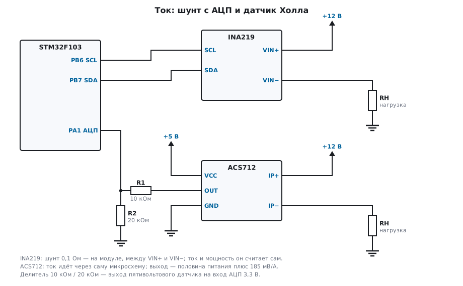
| INA219 | ACS712 | |
|---|---|---|
| principle | shunt, amplifier and ADC inside the chip | Hall sensor with an analog output |
| output | numbers over I²C: current, voltage, power | voltage: 185 mV/A for the 5 A version |
| current path | through the shunt, shared with the measurement | through the chip itself, isolated from the output |
| what to set up | the calibration register | the zero — measure it with no load |
| weak spot | the ±320 mV limit across the shunt | zero and sensitivity depend on the 5 V supply |
101.2 INA219: shunt and calibration
The INA219 measures the voltage across the shunt (10 µV per unit, up to ±320 mV at the default gain) and the bus voltage (4 mV per unit), and it computes current and power itself — if it knows the calibration. It is set by a single number: CAL = 0.04096 / (I_LSB · R_shunt), where I_LSB is the current measurement step.
The step is chosen from the largest current: 3.2 A / 32768 = 97.656 µA — and rounded up to a convenient 100 µA. With a 0.1 Ω shunt this gives CAL = 4096, and the power step — always 20 current steps — is 2 mW. The configuration word after reset is 0x399F: 32 V bus range, ±320 mV shunt, 12 bits, continuous measurement. The range is wider than the chip itself tolerates: the INA219 inputs withstand no more than 26 V, and a bus above 26 V is not connected to it.
#define INA_CONFIG(brng, pg, badc, sadc, mode) \
    ((uint16_t)((brng) << 13 | (pg) << 11 | (badc) << 7 | (sadc) << 3 | (mode)))

uint16_t ina_cal(uint32_t ilsb_ua, uint32_t rshunt_mohm)
{
    return (uint16_t)(40960000u / (ilsb_ua * rshunt_mohm));
}
After power-up the calibration register is empty, and until something is written to it, the current and power registers read zero.
101.3 Reading and conversion
The INA219 registers are 16-bit, most significant byte first; shunt and current are signed numbers, the bus value is in bits 15:3, and the lowest bit is the overflow of the current or power calculation (OVF):
int32_t ina_bus_mv(uint16_t reg)
{
    return (int32_t)(reg >> 3) * 4;
}

int32_t ina_current_ua(uint16_t reg, uint32_t ilsb_ua)
{
    return (int16_t)reg * (int32_t)ilsb_ua;
}

uint32_t ina_power_uw(uint16_t reg, uint32_t ilsb_ua)
{
    return reg * 20u * ilsb_ua;         /* шаг мощности — 20 шагов тока */
}

int ina_read(uint32_t ilsb_ua, int32_t *bus_mv, int32_t *cur_ua, uint32_t *pow_uw)
{
    uint16_t s, b, c, p;
    if (!i2c_read_reg16(INA_ADDR, INA_REG_SHUNT, &s) || !i2c_read_reg16(INA_ADDR, INA_REG_BUS, &b)
        || !i2c_read_reg16(INA_ADDR, INA_REG_CURRENT, &c) || !i2c_read_reg16(INA_ADDR, INA_REG_POWER, &p))
        return 0;
    if ((b & 1u) || (int16_t)s >= 32000 || (int16_t)s <= -32000)
        return 0;                       /* OVF или шунт на пределе ±320 мВ */
    *bus_mv = ina_bus_mv(b);
    *cur_ua = ina_current_ua(c, ilsb_ua);
    *pow_uw = ina_power_uw(p, ilsb_ua);
    return 1;
}
On the PC the bus is replaced by a model of the registers that computes current and power the same way the chip does: from the shunt voltage and the calibration. A current of 1 A through 0.1 Ω is 100 mV across the shunt (10000 units) and a current register of 10000, that is 1.000 A; a 12 V bus gives register 0x5DC2, which yields 12000 mV; the power is 12 W. A current in the opposite direction, −0.5 A, gives 0xEC78 in the shunt register — a negative number in two's complement. And 3.3 A is 330 mV across the shunt, beyond ±320 mV — the shunt full scale, 32000 units. The chip sets the OVF bit only when the computed current or power does not fit, and at CAL = 4096 the current at full scale is 32000, which fits in the register. That is exactly what the model showed: shunt 0x7D00, current 32000, OVF not set. So the driver also looks at the shunt register itself: ±32000 and beyond is an error instead of a wrong number.
101.4 ACS712: the Hall sensor and its zero
The 5 A ACS712 outputs half of its supply at zero current and adds 185 mV for every ampere. At a 5 V supply that is 1.575…3.425 V for ±5 A — more than a 3.3 V ADC input can take, so the output goes through a 2/3 divider (10 kΩ and 20 kΩ). The ADC codes for ±5 A are 1303…2833, at 6.53 mA per code:
int32_t acs_ma(int32_t code, int32_t zero_code)
{
    int64_t n = (int64_t)(code - zero_code) * 4950000;
    const int64_t d = 757575;           /* 4095 · 185 */
    return (int32_t)((n + (n < 0 ? -d / 2 : d / 2)) / d);
}
Current is counted from the zero code, and here is why it has to be measured rather than taken as "half scale". The zero and the sensitivity of the ACS712 are proportional to its own 5 V supply, while the ADC measures relative to its own 3.3 V — these two voltages are unrelated. At exactly 5.0 V supply the zero code is 2068, at +1 A it is 2221, that is 1000 mA. Let the supply sag to 4.9 V — the zero moves to code 2027, and with the zero taken at 5.0 V the sensor shows −268 mA with no current at all. If the zero is measured again, +1 A gives code 2177 — 980 mA: together with the supply, the sensitivity also dropped by 2 %.
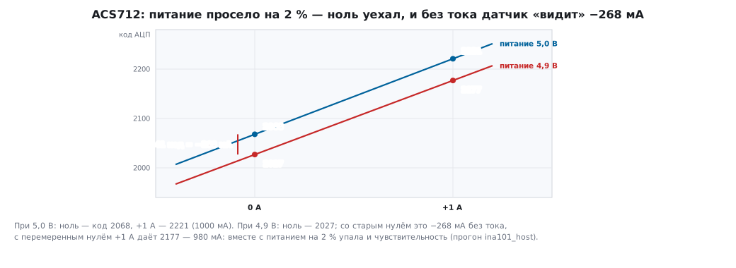
Hence the rules: measure the zero with no load at every start-up, keep the sensor supply stable, and if you need accuracy, measure the 5 V itself on a second ADC channel through the same divider and correct the sensitivity.
101.5 Where to put the shunt
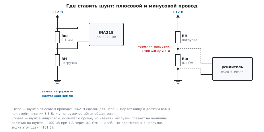
A shunt in the positive wire leaves the load's ground as ground: for a device that shares ground with others this is usually the only correct option, and the INA219 is made exactly for it — it measures a bus up to 26 V while powered from 3.3 V. A shunt in the negative wire is easier for the amplifier, but the load's "ground" then floats by the drop across the shunt, and everything connected to the load sees this offset.
101.6 Pitfalls
The INA219 shows zero current and power. The calibration register was not written: after power-up it is empty, and the chip computes nothing.
The INA219 current jumps by hundreds of times. The register was read least significant byte first; the INA219 sends the most significant byte first.
At high current the reading "froze". There is more than ±320 mV across the shunt: the shunt register hit ±32000, and the OVF bit may not be set — it is about overflow of the calculation. Check the shunt register; use a smaller shunt or a different gain.
The ACS712 shows current with no load. The zero was taken as half scale, and the sensor supply is not exactly 5 V: at 4.9 V you get −268 mA out of nowhere. Measure the zero with no load.
ACS712 readings float along with the 5 V supply. The output is proportional to its supply, while the ADC has its own reference.
ACS712 output straight into the ADC input. Up to 3.425 V at five amperes — more than 3.3 V. Use a divider.
101.7 Summary
- INA219: CAL = 0.04096 / (I_LSB · R_shunt); for 0.1 Ω and a 100 µA step it is 4096, the power step is 2 mW; without calibration current and power read zero.
- Registers are 16 bits, most significant byte first; shunt and current are signed; the lowest bit of the bus register is overflow of the current or power calculation; a shunt voltage beyond ±320 mV shows in its register (±32000).
- 5 A ACS712: 185 mV/A from mid-supply; through a 2/3 divider — 6.53 mA per ADC code.
- Measure the ACS712 zero with no load: at a 4.9 V supply, a zero taken at 5.0 V gives −268 mA, and the sensitivity drops by 2 %.
- Shunt in the positive wire, so the load's ground stays ground.
Next: section 101а "Current and power monitor INA226: 16 bits, calibration register, averaging, threshold alert and energy counting" — the same shunt, but a four times finer step, averaging and alert inside the chip, and counting milliamp-hours.