 Embedded HandbookApps
100б. VL53L0X laser rangefinder: time of flight over I2C, accuracy and speed modes, several sensors on one bus
In section 100 distance was measured with sound: the HC-SR04 answers with a pulse, and one metre gives an echo of 5824 µs. In section 100а a radar split the room into gates of 0.7 m and looked for a person in them. The VL53L0X from ST measures with light: a tiny laser sends pulses, an array of photon counters catches the reflection, and the sensor itself turns the time of flight into millimetres. Outside there is the I2C bus, the XSHUT pin for reset and the GPIO1 pin "measurement ready".
Here: why the time of flight of light means picoseconds and how the sensor gets them; the pins and address of the module; why ST gives not a register description but a C library, and what it does at power-up; single and continuous measurement, the timing budget and noise; readiness on GPIO1 with an interrupt versus polling; three sensors on one bus — powering them up one by one and changing the address; filtering, difficult surfaces, sunlight and glass; a comparison with the HC-SR04 and the radar.
Prerequisites: the ST library for the VL53L0X (API version 1.0.2, STSW-IMG005) — its
copy lives in the hal_st module of the Zephyr project under the BSD-3-Clause license, — and
the sensor driver in Zephyr itself (Apache-2.0). Register addresses, the address
0x29, the boot time, the initialization order and the profiles come from there. The description of the
sensor itself (datasheet) was not used in preparing this section: the supply of the
module, the maximum range and the field of view are not given here. The bench is
the ST library and our layer, built with gcc and run against a model of the sensor
in Python; the same code was built with armclang for the STM32F103 and has not been
run on a board. I²C — section 17, pin interrupts — 7.5, connecting
modules — 95.
Terms used in the documentation
Term Meaning time of flight (ToF) the time light takes to fly to the target and back VCSEL (vertical-cavity surface-emitting laser) a vertical-cavity laser — the source of the pulses SPAD (single photon avalanche diode) an avalanche photodiode that counts single photons reference SPAD reference SPADs: their number is chosen for the reference signal ranging, single / continuous / timed ranging a measurement; one-shot / back to back / by timer measurement timing budget the time allowed for one measurement inter-measurement period the period between measurements in timed mode range status the measurement status: valid, or why not sigma estimate the σ estimate — the expected spread of the range signal rate, ambient rate (MCPS) counts of reflection and background, millions per second crosstalk (XTalk) crosstalk: light reflected by the cover glass VHV, phase calibration the VHV and phase calibrations XSHUT (xshutdown) the reset input, active low new sample ready (GPIO1) the "measurement ready" output
100б.1 Time of flight: why picoseconds
Light travels at 299 792 458 m/s. A target at one metre means 2 m of path and 6.671 ns; one
millimetre of range is 6.671 ps. In the ST library this value is written as the
constant cTOF_per_mm_ps — 6.6 ps per millimetre. The sound of the HC-SR04 needs 5.824 µs for the same
millimetre: 873 000 times longer. Hence the main point: an STM32 timer
cannot catch light. One tick at 72 MHz is 13.89 ns, and in it light travels
a path equal to a range of 2082 mm.
The sensor has its own clock, but it is coarse too: in the library its PLL period is 1655 ps, light covers 496.2 mm in that time, that is 248.1 mm of range. The millimetres come from statistics: the SPADs count single photons, and the sensor averages their arrival time. ST does not disclose exactly how, but the σ estimate formula in the library tells the main thing — the spread falls with the number of caught photons. That is why accuracy is bought with time, and this shows in 100б.4.
Time inside the sensor is counted in macro periods: 2304 PLL ticks multiplied by the laser pulse period in ticks. With a period of 10 ticks the macro period is 38 131 ns, with 14 — 53 384 ns, with 18 — 68 636 ns. The timeouts of the measurement steps are set in macro periods, and through them the library turns the timing budget into registers.
100б.2 The VL53L0X module: pins, supply, address
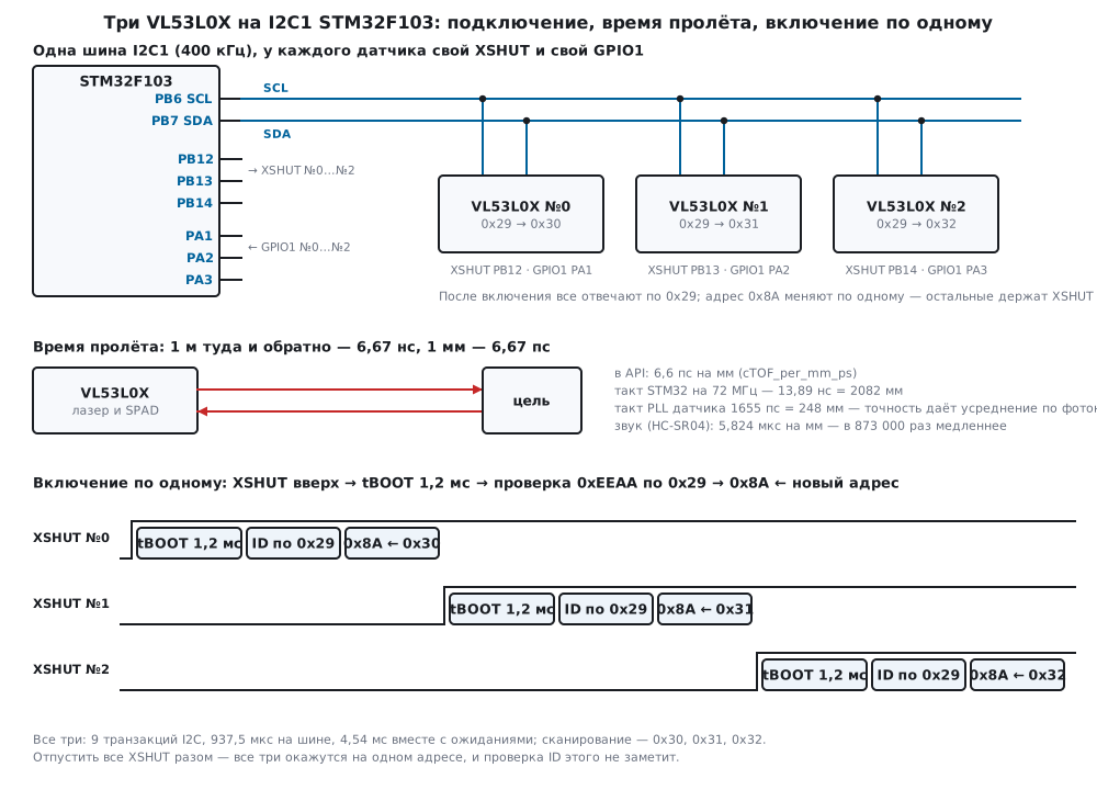
| Pin | What it is | Where in the firmware |
|---|---|---|
| SCL, SDA | I²C, address 0x29 — line bytes 0x52 and 0x53 (17.2) |
PB6, PB7 — I2C1, 400 kHz |
| XSHUT | reset, active low: 0 — the sensor sleeps and stays silent | PB12, PB13, PB14 — open drain |
| GPIO1 | "measurement ready", active low after initialization | PA1, PA2, PA3 — EXTI on the falling edge |
| supply, ground | per the module description | — |
The default address 0x29 and the boot time of up to 1.2 ms after releasing XSHUT
are taken from the Zephyr driver (VL53L0X_INITIAL_ADDR, T_BOOT), and so is the check
"this is a VL53L0X": the word at register 0xC0 equals 0xEEAA. In the Zephyr binding description
XSHUT is called an active-low input. The library configures the GPIO1 output itself:
in StaticInit it writes code 4 — "new
measurement" — to register 0x0A and clears bit 4 of register 0x84, so the line goes
low when a result is ready.
Honestly, little can be said about the supply. By default the library assumes
that the I²C pins of the sensor run at 1.8 V, and for 2.8 V it has to be built with
USE_I2C_2V8 — then it sets bit 0 of register 0x89. The Zephyr driver
does not set this key, and neither does our build. Whether the module has its own regulator,
pull-ups and level shifting depends on the module board; we have no schematic,
so before connecting to 3.3 V this must be checked in the module description.
XSHUT in the firmware is an open-drain output: a one only releases the line, and
a pull-up (your own or on the module) has to raise it. Connecting modules to the
STM32 in general — section 95.
100б.3 Why an "API" and not a register map: what power-up does
Most sensors in this part have a register table: write the mode, read the result. The VL53L0X has none — instead of describing the registers ST gives a C library, as the README of the hal_st module says plainly. The registers have not gone anywhere: the library accesses them over I²C, and its sources show where and what. Our code does the same as the Zephyr driver: only the library touches the registers, and we give it a platform — read and write functions and the polling pause.
VL53L0X_Error VL53L0X_WriteMulti(VL53L0X_DEV Dev, uint8_t index, uint8_t *pdata, uint32_t count)
{
    uint8_t b[1u + TOF_MULTI_MAX];
    if (count > TOF_MULTI_MAX)
        return VL53L0X_ERROR_INVALID_PARAMS;
    b[0] = index;
    memcpy(b + 1, pdata, count);
    return tof_i2c_write(Dev->I2cDevAddr, b, count + 1u) ? VL53L0X_ERROR_CONTROL_INTERFACE : VL53L0X_ERROR_NONE;
}
Each library access is one I²C transaction, multi-byte values most significant byte first. Powering up the sensor follows the same order as in Zephyr:
/* Инициализация — в порядке драйвера Zephyr (vl53l0x_start и vl53l0x_setup_single_shot). */
int tof_init(tof_t *t, const tof_profile_t *p)
{
    uint8_t vhv, phase;
    STEP(10, VL53L0X_DataInit(&t->st));
    STEP(11, VL53L0X_StaticInit(&t->st));
    STEP(12, VL53L0X_PerformRefCalibration(&t->st, &vhv, &phase));
    STEP(13, VL53L0X_PerformRefSpadManagement(&t->st, &t->spads, &t->aperture));
    STEP(14, VL53L0X_SetDeviceMode(&t->st, VL53L0X_DEVICEMODE_SINGLE_RANGING));
    STEP(15, VL53L0X_SetLimitCheckEnable(&t->st, VL53L0X_CHECKENABLE_SIGMA_FINAL_RANGE, 1));
    STEP(16, VL53L0X_SetLimitCheckEnable(&t->st, VL53L0X_CHECKENABLE_SIGNAL_RATE_FINAL_RANGE, 1));
    STEP(17, VL53L0X_SetLimitCheckValue(&t->st, VL53L0X_CHECKENABLE_SIGNAL_RATE_FINAL_RANGE, p->signal_min));
    STEP(18, VL53L0X_SetLimitCheckValue(&t->st, VL53L0X_CHECKENABLE_SIGMA_FINAL_RANGE, p->sigma_max));
    STEP(19, VL53L0X_SetMeasurementTimingBudgetMicroSeconds(&t->st, p->budget_us));
    STEP(20, VL53L0X_SetVcselPulsePeriod(&t->st, VL53L0X_VCSEL_PERIOD_PRE_RANGE, p->vcsel_pre));
    STEP(21, VL53L0X_SetVcselPulsePeriod(&t->st, VL53L0X_VCSEL_PERIOD_FINAL_RANGE, p->vcsel_final));
    return 0;
}
What happens inside, according to the library sources:
- DataInit puts the interface into standard mode (writing
0x00to0x88), reads the "stop variable" from page 1 (register0x91; pages are switched by register0xFF) and enables the checks with default limits: σ no more than 18 mm, signal no less than 0.25 MCPS. - StaticInit reads the factory data — the number of reference SPADs and the map of good ones
— through the strobe in register
0x83and the window0x90, loads the tuning table (243 bytes, marked "update 02/11/2015_v36") and sets GPIO1 to "new measurement". - PerformRefCalibration — two short calibrations, VHV and phase: started
by writing
0x41and0x01to register0x00. - PerformRefSpadManagement chooses the reference SPADs: it starts with three without aperture and adds one at a time until the reference signal comes closest to 20 MCPS. The window is 44 SPADs starting at number 180: twelve without aperture (180…191), the rest with aperture.
- Limits, budget and laser periods. Changing the period recalculates the budget by itself and starts one more phase calibration.
On the bench one such power-up takes 684 transactions and 2621 bytes: 63.3 ms of bus time at 400 kHz, 13 measurements inside and 264 ms together with them. How many reference SPADs the sensor picks depends on its reference signal; in the model it is set to 2.3 MCPS per SPAD, and the calibration stopped at 9 SPADs without aperture — this is a number of the model, not of the sensor.
The price of the library shows in the firmware for three sensors (armclang 6.24, -Os,
Cortex-M3). The whole image has 12 988 bytes of code, of which 10 332 are the ST library,
1124 are our layer tof100c.c, 1316 are the firmware fw100c.c; the linker
threw out everything unused from the library (vl53l0x_api.o had 5096 bytes
of code, 3144 went into the image). Flash — 13 972 bytes, RAM — 1860 bytes without the stack.
Of the RAM, 681 bytes are two library tables, the tuning table (243 bytes) and
the interrupt threshold table (438), declared without const.
100б.4 Single and continuous: timing budget, noise and readiness
The mode is set by a write to register 0x00: 0x01 — one measurement, 0x02 —
back to back without pauses, 0x04 — by timer, with the period in register 0x04 (the library
multiplies the period in milliseconds by the oscillator calibration from register
0xF8). Writing 0x00 stops.
Timing budget. A measurement consists of steps, and the budget is their sum with overheads: 1910 µs for the start, 960 for the end, 660 for the pre-range, 550 for the final range. The remainder goes to the final range. The library does not accept less than 20 000 µs — for 19 000 it returned error −4. What came out after rounding to macro periods:
| Requested, µs | Got, µs | Pre-range, µs | Final range, µs |
|---|---|---|---|
| 20 000 | 19 981 | 8061 | 2402 |
| 33 000 | 32 908 | 8061 | 15 329 |
| 66 000 | 65 853 | 8061 | 48 274 |
| 100 000 | 99 713 | 8061 | 82 134 |
| 200 000 | 199 769 | 8061 | 182 190 |
Noise. The library estimates the range spread itself — with a formula from the number of caught photons of reflection and background. In the model the noise is given by exactly this formula (ported from the library), so the numbers below show the behaviour of the formula, not the behaviour of a real sensor. The target with reflectance 1 is the one for which the library stores a reference signal of 1.42 MCPS at 400 mm; "grey" is 0.3 of it, "black" is 0.05; the signal falls as 1/d². 100 measurements per point, default profile:
| Budget | white, 600 mm | grey, 300 mm | black, 150 mm |
|---|---|---|---|
| 20 ms | 8.94 mm | 9.47 mm | 11.64 mm |
| 33 ms | 6.68 mm | 5.58 mm | 6.98 mm |
| 66 ms | 3.29 mm | 3.05 mm | 4.01 mm |
| 200 ms | 1.74 mm | 1.90 mm | 2.17 mm |
Ten times more time gives roughly five times less spread. The estimate of the library itself on the white target is 9.50, 5.90, 3.69 and 1.97 mm.
Profiles. The default one is what the library sets: a signal limit of
0.25 MCPS, σ up to 18 mm, laser periods of 14 and 10 ticks (12…18 and 8…14 is what
the library allows). The long-range one is as in the Zephyr driver: 0.1 MCPS, 60 mm,
periods 18 and 14. The signal limit goes into register 0x44 in 9.7 format:
0x0020 is exactly 0.25, 0x000C is 0.094. If the signal falls as 1/d², then
the white target is lost beyond 953 mm in the default profile and beyond 1557 mm in the long-range one,
the grey one beyond 522 and 853 mm, the black one beyond 213 and 348 mm. A run with a budget of 33 ms
confirmed this: white at 1200 mm — 0 valid of 100 and 100 of 100, at
1500 mm in long range — 93; grey at 600 mm — 0 and 100; black at 300 mm — 0 and
100. The price is spread: white at 600 mm — 6.68 mm in the default and 8.15 mm in the
long-range profile. The model does not account for the pulse energy, so in it the long-range profile is
only softer limits.
Readiness. The library waits for the end of a measurement by polling: it reads register
0x13 (ready when the lowest three bits equal 4), between reads it calls the platform
pause — 1000 µs in our case — and gives up after 2000 attempts. One read of the
register takes 97.5 µs of bus at 400 kHz. It can be done differently: start a measurement and
wait for the falling edge of GPIO1 on EXTI, leaving the bus alone. Budget 33 ms, 20 measurements each:
| Transactions per measurement | Bytes | Bus busy | |
|---|---|---|---|
| single, polling | 44 | 177 | 12.5 % |
| single, GPIO1 | 13 | 53 | 3.7 % |
| continuous, GPIO1 | 4 | 25 | — |
In continuous mode one result takes four transactions: 12 bytes from
0x14 (range, status, signal and background) and clearing the interrupt. Back to back
the results came every 32 908 µs — exactly the budget, by a 100 ms timer — every
100 000 µs.
/* Забрать результат: 12 байт с 0x14 разбирает API, оценку σ он же считает при этом; затем снять прерывание —
 * пока его не снять, GPIO1 стоит внизу. */
int tof_fetch(tof_t *t, tof_meas_t *m)
{
    VL53L0X_RangingMeasurementData_t r;
    FixPoint1616_t sigma = 0;
    memset(&r, 0, sizeof r);                       /* API смотрит в RangeStatus прошлого замера — обнуляем */
    STEP(30, VL53L0X_GetRangingMeasurementData(&t->st, &r));
    STEP(31, VL53L0X_GetLimitCheckCurrent(&t->st, VL53L0X_CHECKENABLE_SIGMA_FINAL_RANGE, &sigma));
    STEP(32, VL53L0X_ClearInterruptMask(&t->st, 0));
    m->mm = r.RangeMilliMeter;
    m->status = r.RangeStatus;
    m->signal = r.SignalRateRtnMegaCps;
    m->ambient = r.AmbientRateRtnMegaCps;
    m->sigma = sigma;
    return 0;
}
Clearing the interrupt is mandatory. GPIO1 stays low until a one is written to register 0x0B
— there will be no new falling edge, and EXTI will not fire again. In the model
the sensor in continuous mode was not read for 200 ms: one falling edge, then five
results overwritten by the next ones, and the line stayed low.
void EXTI1_IRQHandler(void)
{
    EXTI->PR = EXTI_PR_PR1;
    tof_on_gpio1(&T[0]);
}
/* Проверить флаги и уснуть атомарно: прерывание между проверкой и WFI всё равно разбудит. */
void tof_idle(void)
{
    __disable_irq();
    if (!any_irq())
        __WFI();
    __enable_irq();
}
The handler only sets a flag, and the main loop does the reading: a bus access from
the interrupt would collide with a transfer in progress at that moment. Sleeping happens
with interrupts disabled: if the falling edge arrives between checking the flags and WFI,
the pending interrupt still wakes the processor.
100б.5 Several sensors on one bus: XSHUT and address change
All VL53L0X answer at 0x29 after power-up. The address is changed by writing to
register 0x8A, but only for whoever is listening right now — so the sensors
are powered up one by one: all XSHUT low, then each one is released, the boot is waited for,
it is checked that a VL53L0X really answers at 0x29, and it is moved to its own
address.
/* Отпустить XSHUT одного датчика, дождаться загрузки, проверить, что по 0x29 отвечает VL53L0X,
 * и перевести его на свой адрес. Остальные датчики в это время держат XSHUT внизу и молчат. */
int tof_wake(tof_t *t, uint8_t idx, uint8_t addr7)
{
    uint16_t id = 0;
    memset(t, 0, sizeof *t);
    t->idx = idx;
    t->st.I2cDevAddr = TOF_ADDR_DEFAULT;
    tof_xshut(idx, 1);
    tof_delay_us(TOF_BOOT_US);
    STEP(1, VL53L0X_RdWord(&t->st, TOF_REG_ID, &id));
    if (id != TOF_CHIP_ID)
        return 2;
    if (addr7 != TOF_ADDR_DEFAULT) {
        STEP(3, VL53L0X_SetDeviceAddress(&t->st, (uint8_t)(addr7 << 1)));   /* API ждёт 8-битный адрес */
        t->st.I2cDevAddr = addr7;
        id = 0;
        STEP(4, VL53L0X_RdWord(&t->st, TOF_REG_ID, &id));
        if (id != TOF_CHIP_ID)
            return 5;
    }
    return 0;
}
The library function VL53L0X_SetDeviceAddress expects an eight-bit address and itself
divides it by 2 — the confusion from 17.2 in its pure form: passing it 0x30
means getting 0x18. The Zephyr driver passes the doubled address, and so do we.
On the bench the three sensors came up in 9 transactions and 39 bytes: 937.5 µs of bus and
4537.5 µs together with waiting for the boot; the scan found 0x30, 0x31,
0x32. The model also showed three mistakes:
- Right after XSHUT. An access without a pause gets no acknowledge; after 1200 µs the sensor answers.
- All XSHUT at once. The scan finds one address,
0x29. Writing the new address is acknowledged — and all three move to0x30. The ID check at0x30reads0xEEAA: all three have the same word, and the open drain ANDs them together without a trace. A collision cannot be caught this way. - Resetting one. Sensor №1 had XSHUT pulled down and released — it is back at
0x29, the scan shows0x29,0x30,0x32. The address is not kept; after a reset or a supply dropout the sensor is brought up again. In the model this is an assumption; the Zephyr driver does the same — after resuming from sleep it calls the whole initialization again.
In Zephyr the address change is enabled by the CONFIG_VL53L0X_RECONFIGURE_ADDRESS key,
and then every sensor must have an XSHUT pin. Three sensors, each in
continuous mode with its own GPIO1, gave 30.36 measurements per
second per sensor on the bench with the bus 5.4 % busy and not a single lost
result. The same three in turn, single-shot and with polling — 9.72 per
second and 12.5 % of the bus.
100б.6 Filtering, difficult surfaces, light and glass; comparison with the HC-SR04 and the radar
Each measurement comes with a status. The library combines the sensor code (bits
6:3 of the byte at 0x14) and its own checks into one number: 0 — valid, 1 — σ above the
limit, 2 — weak signal, 3 — too close, 4 — phase failure, 5 — device
failure. The filter starts by throwing out everything non-zero; of what
remains it takes the median of the last five.
/* ── фильтр: недостоверные статусы — мимо, из годных — медиана последних TOF_MED ── */
int tof_filter(tof_filt_t *f, const tof_meas_t *m)
{
    uint16_t s[TOF_MED];
    if (m->status != 0) {
        f->dropped++;
    } else {
        f->taken++;
        f->win[f->pos] = m->mm;
        f->pos = (uint8_t)((f->pos + 1u) % TOF_MED);
        if (f->n < TOF_MED)
            f->n++;
    }
    if (f->n == 0)
        return -1;
    memcpy(s, f->win, sizeof s);
    for (uint8_t i = 1; i < f->n; i++)             /* вставками: окно маленькое */
        for (uint8_t j = i; j > 0 && s[j - 1] > s[j]; j--) {
            uint16_t x = s[j];
            s[j] = s[j - 1];
            s[j - 1] = x;
        }
    return s[f->n / 2];
}
Continuous mode, budget 33 ms, 200 measurements each:
| Scene (model) | Valid | Spread of valid | After the median | Worst error: all / median |
|---|---|---|---|---|
| white, 600 mm | 200 | 6.08 mm | 3.88 mm | 16 / 10 mm |
| white, 600 mm, background 2.5 MCPS | 52 (148 — status 1) | 18.57 mm | 12.96 mm | 46 / 29 mm |
| white, 300 mm, background 2.5 MCPS | 200 | 3.67 mm | 2.00 mm | 11 / 6 mm |
| white, 950 mm — at the limit | 126 (74 — status 2) | 9.51 mm | 5.24 mm | 32 / 12 mm |
| empty | 0 (200 — status 2) | — | — | 1606 mm |
Sunlight is background: photons not related to the pulse. The σ formula grows with the ratio of background to signal, so background hits distant and dark targets: at 600 mm, of 200 measurements 52 stayed valid, at 300 mm — all of them. The empty scene is the main argument for checking the status: in the model the range without a reflection is scattered from 0 to 2606 mm. What a real sensor puts into the register when there is nothing to aim at, we did not check. At the very edge of the range the invalid values in the model are close to the truth (from 933 to 976 mm), but the sensor does not vouch for them.
Black. The signal is proportional to the reflectance: the black target is 20 times darker than
the white one, and in the default profile it is lost already beyond 213 mm (100б.4).
Shiny and tilted. A mirror surface reflects the pulse by the
law of reflection, not in all directions: at an angle the light will not come back to the sensor,
head-on it comes back too bright. Glass. A cover in front of the sensor
itself reflects part of the pulse into the receiver — this is crosstalk. For this
case the library has an offset calibration and crosstalk compensation
(PerformOffsetCalibration, PerformXTalkCalibration,
SetXTalkCompensationEnable); by default the compensation is off. The model gives no numbers for
these three cases — this is a qualitative picture.
| HC-SR04 (section 100) | HLK-LD2420 (section 100а) | VL53L0X | |
|---|---|---|---|
| measures with | sound, echo of 5824 µs per metre | a 24 GHz radar | light, 6.671 ns per metre |
| sees | the nearest surface | a person, even a motionless one | the surface it is pointed at |
| result | pulse length — measured by a timer | gates of 0.7 m, "present / absent" | millimetres over I²C |
| time per answer | up to the 25 ms timeout | 10 times a second | budget from 20 ms |
| depends on | temperature: +3.7 % in frost | gate thresholds | reflectance, background, budget |
| several on one device | disturb each other — take turns | — | one address — XSHUT and address change |
For "is anyone in the room" you need the radar; for "how far is the wall" over metres — ultrasound; for millimetres over tens of centimetres, for several sensors on one board and where sound dies on soft surfaces — the VL53L0X.
100б.7 Pitfalls
The second sensor is not found, and the first answers at someone else's address. All XSHUT
were released at once: every sensor got the write to 0x8A. Power them up one by one.
After the change the address is 0x18 instead of 0x30. VL53L0X_SetDeviceAddress
expects an eight-bit address and divides it by 2. Pass the doubled one.
The first access after XSHUT gets no acknowledge. The boot was not waited for: up to 1.2 ms.
After a supply dropout the sensor "disappeared". It went back to 0x29. Repeat
the one-by-one power-up and the initialization.
The interrupt came once and never again. The interrupt was not cleared
by writing to 0x0B: GPIO1 stays low, there is no new falling edge.
The range jumps by hundreds of millimetres. The status is ignored: invalid measurements are used. Everything with a non-zero status goes out.
In sunlight distant targets disappear, near ones are fine. Background inflates σ; the long-range profile, a larger budget or shade.
The bus is busy while the sensors are still measuring. Readiness polling: 44 transactions per measurement instead of 13. Wait for GPIO1.
A budget of 19 ms cannot be set. The library does not accept less than 20 000 µs and returns error −4 — check the return code.
More RAM is gone than expected. Two library tables without const — 681 bytes,
plus the library state for every sensor.
Through glass the range is too short or stuck. Light reflects from the cover. Offset calibration and crosstalk compensation — or a sensor without glass.
100б.8 Summary
- The time of flight of light is 6.671 ns per metre and 6.671 ps per millimetre; an STM32 tick at 72 MHz equals 2082 mm. The sensor collects millimetres from photon statistics.
- There is no register map: the ST library touches the registers, our code gives it read, write and a pause. Powering up one sensor takes 684 transactions, 2621 bytes and 13 calibration measurements inside; in the firmware the library is 10 332 bytes of code out of 12 988.
- The budget starts at 20 000 µs; the spread falls with time: 8.94 mm in 20 ms and 1.74 mm in 200 ms on a white target at 600 mm (a model with the library σ formula).
- Profiles: 0.25 MCPS and 18 mm versus 0.1 MCPS and 60 mm. A white target with a signal falling as 1/d² — up to 953 and up to 1557 mm.
- Readiness — on GPIO1 with EXTI: 13 transactions per single measurement
instead of 44, in continuous mode 4. Clear the interrupt by writing to
0x0B. - Several sensors: the address is
0x29for all; power them up one by one with XSHUT, wait 1.2 ms, write the new address to0x8A. Three sensors — 30.36 measurements per second each with 5.4 % of the bus. - A non-zero status — throw the measurement away, take the median of the valid ones: a spread of 6.08 mm becomes 3.88 mm.
Full sources
The layer over the ST library and the firmware for three sensors. The library itself is an unchanged copy
from hal_st, in _verify/tof100c/st/; the platform headers are our own,
the bench host100c.c and the model model100c.py are in _verify/tof100c/.
vl53l0x_platform.h — the library platform: the device and the register access functions.
/* Раздел 100б: платформа API ST VL53L0X — какое устройство и как до него добраться.
 * API ST зовёт эти функции для каждого обращения к регистрам; реализация — в tof100c.c,
 * поверх шины из tof100c.h (прошивка — I2C1 F103, стенд — строки к модели). */
#ifndef VL53L0X_PLATFORM_H
#define VL53L0X_PLATFORM_H
#include "vl53l0x_def.h"
#include "vl53l0x_platform_log.h"

typedef struct {
    VL53L0X_DevData_t Data;     /* состояние API — его поле, по имени Data */
    uint8_t I2cDevAddr;         /* адрес на шине, 7 бит (у API ST в SetDeviceAddress — 8 бит) */
} VL53L0X_Dev_t;
typedef VL53L0X_Dev_t *VL53L0X_DEV;

#define PALDevDataGet(Dev, field) (Dev->Data.field)
#define PALDevDataSet(Dev, field, data) ((Dev->Data.field) = (data))

VL53L0X_Error VL53L0X_WriteMulti(VL53L0X_DEV Dev, uint8_t index, uint8_t *pdata, uint32_t count);
VL53L0X_Error VL53L0X_ReadMulti(VL53L0X_DEV Dev, uint8_t index, uint8_t *pdata, uint32_t count);
VL53L0X_Error VL53L0X_WrByte(VL53L0X_DEV Dev, uint8_t index, uint8_t data);
VL53L0X_Error VL53L0X_WrWord(VL53L0X_DEV Dev, uint8_t index, uint16_t data);
VL53L0X_Error VL53L0X_WrDWord(VL53L0X_DEV Dev, uint8_t index, uint32_t data);
VL53L0X_Error VL53L0X_RdByte(VL53L0X_DEV Dev, uint8_t index, uint8_t *data);
VL53L0X_Error VL53L0X_RdWord(VL53L0X_DEV Dev, uint8_t index, uint16_t *data);
VL53L0X_Error VL53L0X_RdDWord(VL53L0X_DEV Dev, uint8_t index, uint32_t *data);
VL53L0X_Error VL53L0X_UpdateByte(VL53L0X_DEV Dev, uint8_t index, uint8_t AndData, uint8_t OrData);
VL53L0X_Error VL53L0X_PollingDelay(VL53L0X_DEV Dev);
#endif
tof100c.h — our layer: the bus, the profiles, the sensor state.
/* Раздел 100б: несколько VL53L0X на одной шине I2C поверх API ST (STSW-IMG005 1.0.2, копия из hal_st Zephyr).
 * Регистры трогает только API ST; наш слой — платформа API (функции VL53L0X_WrByte и др.), включение датчиков
 * по одному через XSHUT со сменой адреса, инициализация в порядке драйвера Zephyr, режимы, готовность по GPIO1
 * и фильтр. Шину и выводы даёт прошивка (fw100c.c — I2C1 STM32F103) или стенд (host100c.c — строки к модели). */
#ifndef TOF100C_H
#define TOF100C_H
#include <stdint.h>
#include "vl53l0x_api.h"

#define TOF_ADDR_DEFAULT 0x29u      /* адрес после включения — VL53L0X_INITIAL_ADDR в драйвере Zephyr */
#define TOF_REG_ID       0xC0u      /* слово 0xEEAA: VL53L0X_REG_WHO_AM_I и VL53L0X_CHIP_ID там же */
#define TOF_CHIP_ID      0xEEAAu
#define TOF_BOOT_US      1200u      /* tBOOT: загрузка до 1,2 мс после отпускания XSHUT (там же) */
#define TOF_POLL_US      1000u      /* пауза между опросами готовности — наше значение */
#define TOF_MED          5u         /* окно медианы */

/* ── шина и выводы: реализует прошивка или стенд ── */
int  tof_i2c_write(uint8_t addr7, const uint8_t *buf, uint32_t n);    /* 0 — ведомый подтвердил всё */
int  tof_i2c_read(uint8_t addr7, uint8_t reg, uint8_t *buf, uint32_t n);
void tof_delay_us(uint32_t us);
void tof_xshut(uint8_t idx, int run);   /* run = 1 — отпустить XSHUT (датчик работает), 0 — прижать к земле */
void tof_idle(void);                    /* ждать прерывания: прошивка — WFI, стенд — до спада GPIO1 в модели */

typedef struct {
    uint16_t mm;            /* RangeMilliMeter */
    uint8_t status;         /* RangeStatus API: 0 — годен, 1 сигма, 2 сигнал, 3 мин. дальность, 4 фаза, 5 сбой */
    uint32_t signal, ambient;   /* MCPS, 16.16 */
    uint32_t sigma;         /* оценка σ, мм, 16.16 — считает API */
} tof_meas_t;

typedef struct {
    uint16_t win[TOF_MED];
    uint8_t n, pos;
    uint32_t taken, dropped;
} tof_filt_t;

typedef struct {
    uint32_t budget_us;             /* время на одно измерение */
    uint8_t vcsel_pre, vcsel_final; /* периоды импульса лазера, такты PLL */
    FixPoint1616_t signal_min;      /* предел сигнала, MCPS */
    FixPoint1616_t sigma_max;       /* предел σ, мм */
} tof_profile_t;

typedef struct {
    VL53L0X_Dev_t st;               /* состояние API ST */
    uint8_t idx;                    /* номер вывода XSHUT и GPIO1 */
    volatile uint8_t irq;           /* GPIO1 упал — ставит обработчик EXTI */
    VL53L0X_Error err;              /* код API на шаге, где встали */
    uint32_t spads;                 /* итог калибровки опорных SPAD */
    uint8_t aperture;
    tof_filt_t f;
} tof_t;

extern const tof_profile_t TOF_DEFAULT, TOF_LONG;

int  tof_probe(uint8_t addr7);
int  tof_wake(tof_t *t, uint8_t idx, uint8_t addr7);
void tof_sleep_all(uint8_t n);
int  tof_init(tof_t *t, const tof_profile_t *p);
int  tof_single(tof_t *t, tof_meas_t *m, int use_irq);
int  tof_start(tof_t *t, uint32_t period_ms);
int  tof_stop(tof_t *t);
int  tof_fetch(tof_t *t, tof_meas_t *m);
void tof_on_gpio1(tof_t *t);
int  tof_filter(tof_filt_t *f, const tof_meas_t *m);
#endif
tof100c.c — the platform, one-by-one power-up, initialization, measurements, filter.
/* Раздел 100б: платформа API ST и слой «несколько датчиков на одной шине». Общий для прошивки и стенда. */
#include <string.h>
#include "tof100c.h"

/* Профили. Обычный — то, что API ставит сам: пределы 0,25 MCPS и 18 мм (DataInit), периоды 14 и 10 (таблица
 * настроек). Дальний — как в драйвере Zephyr: 0,1 MCPS, 60 мм, периоды 18 и 14. Бюджет у обоих 33 мс (Zephyr). */
const tof_profile_t TOF_DEFAULT = {33000u, 14u, 10u, (FixPoint1616_t)(65536u / 4u), (FixPoint1616_t)(18u * 65536u)};
const tof_profile_t TOF_LONG = {33000u, 18u, 14u, (FixPoint1616_t)(65536u / 10u), (FixPoint1616_t)(60u * 65536u)};

/* ── платформа API ST: каждое обращение к регистру — одна транзакция I2C ── */
#define TOF_MULTI_MAX 16u

VL53L0X_Error VL53L0X_WriteMulti(VL53L0X_DEV Dev, uint8_t index, uint8_t *pdata, uint32_t count)
{
    uint8_t b[1u + TOF_MULTI_MAX];
    if (count > TOF_MULTI_MAX)
        return VL53L0X_ERROR_INVALID_PARAMS;
    b[0] = index;
    memcpy(b + 1, pdata, count);
    return tof_i2c_write(Dev->I2cDevAddr, b, count + 1u) ? VL53L0X_ERROR_CONTROL_INTERFACE : VL53L0X_ERROR_NONE;
}

VL53L0X_Error VL53L0X_ReadMulti(VL53L0X_DEV Dev, uint8_t index, uint8_t *pdata, uint32_t count)
{
    return tof_i2c_read(Dev->I2cDevAddr, index, pdata, count) ? VL53L0X_ERROR_CONTROL_INTERFACE : VL53L0X_ERROR_NONE;
}

static VL53L0X_Error wr_be(VL53L0X_DEV Dev, uint8_t index, uint32_t v, uint32_t n)
{
    uint8_t b[4];
    for (uint32_t i = 0; i < n; i++)               /* старший байт первым */
        b[i] = (uint8_t)(v >> (8u * (n - 1u - i)));
    return VL53L0X_WriteMulti(Dev, index, b, n);
}

static VL53L0X_Error rd_be(VL53L0X_DEV Dev, uint8_t index, uint32_t *v, uint32_t n)
{
    uint8_t b[4];
    VL53L0X_Error e = VL53L0X_ReadMulti(Dev, index, b, n);
    *v = 0;
    for (uint32_t i = 0; i < n; i++)
        *v = (*v << 8) | b[i];
    return e;
}

VL53L0X_Error VL53L0X_WrByte(VL53L0X_DEV Dev, uint8_t index, uint8_t data) { return wr_be(Dev, index, data, 1); }
VL53L0X_Error VL53L0X_WrWord(VL53L0X_DEV Dev, uint8_t index, uint16_t data) { return wr_be(Dev, index, data, 2); }
VL53L0X_Error VL53L0X_WrDWord(VL53L0X_DEV Dev, uint8_t index, uint32_t data) { return wr_be(Dev, index, data, 4); }

VL53L0X_Error VL53L0X_RdByte(VL53L0X_DEV Dev, uint8_t index, uint8_t *data)
{
    uint32_t v;
    VL53L0X_Error e = rd_be(Dev, index, &v, 1);
    *data = (uint8_t)v;
    return e;
}

VL53L0X_Error VL53L0X_RdWord(VL53L0X_DEV Dev, uint8_t index, uint16_t *data)
{
    uint32_t v;
    VL53L0X_Error e = rd_be(Dev, index, &v, 2);
    *data = (uint16_t)v;
    return e;
}

VL53L0X_Error VL53L0X_RdDWord(VL53L0X_DEV Dev, uint8_t index, uint32_t *data) { return rd_be(Dev, index, data, 4); }

VL53L0X_Error VL53L0X_UpdateByte(VL53L0X_DEV Dev, uint8_t index, uint8_t AndData, uint8_t OrData)
{
    uint8_t v;
    VL53L0X_Error e = VL53L0X_RdByte(Dev, index, &v);
    return e ? e : VL53L0X_WrByte(Dev, index, (uint8_t)((v & AndData) | OrData));
}

VL53L0X_Error VL53L0X_PollingDelay(VL53L0X_DEV Dev)
{
    (void)Dev;
    tof_delay_us(TOF_POLL_US);
    return VL53L0X_ERROR_NONE;
}

/* ── включение по одному и смена адреса ── */
#define STEP(n, call) do { VL53L0X_Error e_ = (call); if (e_ != VL53L0X_ERROR_NONE) { t->err = e_; return (n); } } while (0)

int tof_probe(uint8_t addr7)
{
    return tof_i2c_write(addr7, 0, 0) == 0;        /* только адрес: ответил ли кто-нибудь ACK */
}

void tof_sleep_all(uint8_t n)
{
    for (uint8_t i = 0; i < n; i++)
        tof_xshut(i, 0);                           /* все в сброс: после него адрес снова 0x29 */
    tof_delay_us(TOF_BOOT_US);
}

/* Отпустить XSHUT одного датчика, дождаться загрузки, проверить, что по 0x29 отвечает VL53L0X,
 * и перевести его на свой адрес. Остальные датчики в это время держат XSHUT внизу и молчат. */
int tof_wake(tof_t *t, uint8_t idx, uint8_t addr7)
{
    uint16_t id = 0;
    memset(t, 0, sizeof *t);
    t->idx = idx;
    t->st.I2cDevAddr = TOF_ADDR_DEFAULT;
    tof_xshut(idx, 1);
    tof_delay_us(TOF_BOOT_US);
    STEP(1, VL53L0X_RdWord(&t->st, TOF_REG_ID, &id));
    if (id != TOF_CHIP_ID)
        return 2;
    if (addr7 != TOF_ADDR_DEFAULT) {
        STEP(3, VL53L0X_SetDeviceAddress(&t->st, (uint8_t)(addr7 << 1)));   /* API ждёт 8-битный адрес */
        t->st.I2cDevAddr = addr7;
        id = 0;
        STEP(4, VL53L0X_RdWord(&t->st, TOF_REG_ID, &id));
        if (id != TOF_CHIP_ID)
            return 5;
    }
    return 0;
}

/* Инициализация — в порядке драйвера Zephyr (vl53l0x_start и vl53l0x_setup_single_shot). */
int tof_init(tof_t *t, const tof_profile_t *p)
{
    uint8_t vhv, phase;
    STEP(10, VL53L0X_DataInit(&t->st));
    STEP(11, VL53L0X_StaticInit(&t->st));
    STEP(12, VL53L0X_PerformRefCalibration(&t->st, &vhv, &phase));
    STEP(13, VL53L0X_PerformRefSpadManagement(&t->st, &t->spads, &t->aperture));
    STEP(14, VL53L0X_SetDeviceMode(&t->st, VL53L0X_DEVICEMODE_SINGLE_RANGING));
    STEP(15, VL53L0X_SetLimitCheckEnable(&t->st, VL53L0X_CHECKENABLE_SIGMA_FINAL_RANGE, 1));
    STEP(16, VL53L0X_SetLimitCheckEnable(&t->st, VL53L0X_CHECKENABLE_SIGNAL_RATE_FINAL_RANGE, 1));
    STEP(17, VL53L0X_SetLimitCheckValue(&t->st, VL53L0X_CHECKENABLE_SIGNAL_RATE_FINAL_RANGE, p->signal_min));
    STEP(18, VL53L0X_SetLimitCheckValue(&t->st, VL53L0X_CHECKENABLE_SIGMA_FINAL_RANGE, p->sigma_max));
    STEP(19, VL53L0X_SetMeasurementTimingBudgetMicroSeconds(&t->st, p->budget_us));
    STEP(20, VL53L0X_SetVcselPulsePeriod(&t->st, VL53L0X_VCSEL_PERIOD_PRE_RANGE, p->vcsel_pre));
    STEP(21, VL53L0X_SetVcselPulsePeriod(&t->st, VL53L0X_VCSEL_PERIOD_FINAL_RANGE, p->vcsel_final));
    return 0;
}

/* ── измерения ── */
void tof_on_gpio1(tof_t *t)
{
    t->irq = 1;
}

/* Забрать результат: 12 байт с 0x14 разбирает API, оценку σ он же считает при этом; затем снять прерывание —
 * пока его не снять, GPIO1 стоит внизу. */
int tof_fetch(tof_t *t, tof_meas_t *m)
{
    VL53L0X_RangingMeasurementData_t r;
    FixPoint1616_t sigma = 0;
    memset(&r, 0, sizeof r);                       /* API смотрит в RangeStatus прошлого замера — обнуляем */
    STEP(30, VL53L0X_GetRangingMeasurementData(&t->st, &r));
    STEP(31, VL53L0X_GetLimitCheckCurrent(&t->st, VL53L0X_CHECKENABLE_SIGMA_FINAL_RANGE, &sigma));
    STEP(32, VL53L0X_ClearInterruptMask(&t->st, 0));
    m->mm = r.RangeMilliMeter;
    m->status = r.RangeStatus;
    m->signal = r.SignalRateRtnMegaCps;
    m->ambient = r.AmbientRateRtnMegaCps;
    m->sigma = sigma;
    return 0;
}

/* Однократное измерение. use_irq = 0 — опрос регистра готовности через паузы TOF_POLL_US (так делает
 * PerformSingleMeasurement); use_irq = 1 — ждать спада GPIO1, шина в это время свободна. */
int tof_single(tof_t *t, tof_meas_t *m, int use_irq)
{
    STEP(40, VL53L0X_SetDeviceMode(&t->st, VL53L0X_DEVICEMODE_SINGLE_RANGING));
    if (!use_irq) {
        STEP(41, VL53L0X_PerformSingleMeasurement(&t->st));
    } else {
        t->irq = 0;
        STEP(42, VL53L0X_StartMeasurement(&t->st));
        while (!t->irq)
            tof_idle();
    }
    return tof_fetch(t, m);
}

/* Непрерывный режим: period_ms = 0 — измерения подряд, иначе одно на period_ms. */
int tof_start(tof_t *t, uint32_t period_ms)
{
    if (period_ms == 0) {
        STEP(50, VL53L0X_SetDeviceMode(&t->st, VL53L0X_DEVICEMODE_CONTINUOUS_RANGING));
    } else {
        STEP(51, VL53L0X_SetDeviceMode(&t->st, VL53L0X_DEVICEMODE_CONTINUOUS_TIMED_RANGING));
        STEP(52, VL53L0X_SetInterMeasurementPeriodMilliSeconds(&t->st, period_ms));
    }
    t->irq = 0;
    STEP(53, VL53L0X_StartMeasurement(&t->st));
    return 0;
}

int tof_stop(tof_t *t)
{
    STEP(60, VL53L0X_StopMeasurement(&t->st));
    return 0;
}

/* ── фильтр: недостоверные статусы — мимо, из годных — медиана последних TOF_MED ── */
int tof_filter(tof_filt_t *f, const tof_meas_t *m)
{
    uint16_t s[TOF_MED];
    if (m->status != 0) {
        f->dropped++;
    } else {
        f->taken++;
        f->win[f->pos] = m->mm;
        f->pos = (uint8_t)((f->pos + 1u) % TOF_MED);
        if (f->n < TOF_MED)
            f->n++;
    }
    if (f->n == 0)
        return -1;
    memcpy(s, f->win, sizeof s);
    for (uint8_t i = 1; i < f->n; i++)             /* вставками: окно маленькое */
        for (uint8_t j = i; j > 0 && s[j - 1] > s[j]; j--) {
            uint16_t x = s[j];
            s[j] = s[j - 1];
            s[j - 1] = x;
        }
    return s[f->n / 2];
}
fw100c.c — the STM32F103 firmware: I2C1, XSHUT, EXTI, three sensors.
/* fw100c.c — раздел 100б: три VL53L0X на одной шине I2C1 STM32F103 (BluePill), 72 МГц.
 * I2C1: PB6 — SCL, PB7 — SDA, 400 кГц (быстрый режим, как в 17.3). XSHUT датчиков — PB12, PB13, PB14,
 * выходы с открытым стоком: 0 — датчик в сбросе, 1 — отпущен (поднимает подтяжка). GPIO1 датчиков — PA1, PA2,
 * PA3, входы с подтяжкой, EXTI1…EXTI3 по спаду: API ставит GPIO1 «новое измерение, активный ноль».
 * После включения датчики по одному получают адреса 0x30, 0x31, 0x32 и меряют каждые 50 мс.
 * Тактирование до 72 МГц — как в разделе 6 (здесь не повторяется); APB1 = 36 МГц. */
#include "stm32f10x.h"
#include "tof100c.h"

#define CPU_HZ 72000000u
#define APB1_MHZ 36u
#define I2C_FAST_CCR (APB1_MHZ * 1000000u / (3u * 400000u))   /* F/S = 1, DUTY = 0: Tlow = 2 Thigh */
#define I2C_FAST_TRISE (APB1_MHZ * 300u / 1000u + 1u)         /* фронт до 300 нс */
#define I2C_SPIN 20000u                                        /* предел ожидания флага, витков */
#define PERIOD_MS 50u

_Static_assert(I2C_FAST_CCR == 30u, "CCR = 30: 36 МГц / (3 · 30) = 400 кГц");
_Static_assert(I2C_FAST_TRISE == 11u, "TRISE = 11");

static tof_t T[3];
static const uint8_t ADDR[3] = {0x30u, 0x31u, 0x32u};
volatile int16_t dist_mm[3];                   /* итог фильтра; отрицательное — номер шага, где встали */

/* ── I2C1, ведущий, опросом; на каждом ожидании — предел ── */
static int wait1(uint32_t mask)
{
    for (uint32_t n = 0; n < I2C_SPIN; n++) {
        uint32_t sr = I2C1->SR1;
        if (sr & I2C_SR1_AF) {                 /* нет подтверждения */
            I2C1->SR1 = (uint16_t)~I2C_SR1_AF;
            return 1;
        }
        if (sr & mask)
            return 0;
    }
    return 2;
}

static void stop(void)
{
    I2C1->CR1 |= I2C_CR1_STOP;
    while (I2C1->CR1 & I2C_CR1_STOP) {
    }
}

static int start(uint8_t a8)
{
    I2C1->CR1 |= I2C_CR1_START;
    if (wait1(I2C_SR1_SB))
        return 1;
    I2C1->DR = a8;
    if (wait1(I2C_SR1_ADDR)) {
        stop();
        return 1;
    }
    return 0;
}

int tof_i2c_write(uint8_t addr7, const uint8_t *buf, uint32_t n)
{
    if (start((uint8_t)(addr7 << 1)))
        return 1;
    (void)I2C1->SR1;
    (void)I2C1->SR2;                           /* ADDR снят: SR1, затем SR2 (17.4) */
    for (uint32_t i = 0; i < n; i++) {
        if (wait1(I2C_SR1_TXE)) {
            stop();
            return 1;
        }
        I2C1->DR = buf[i];
    }
    int e = n ? wait1(I2C_SR1_BTF) : 0;
    stop();
    return e;
}

/* Приём по RM0008 (ведущий приёмник): один байт — ACK снять до снятия ADDR; два — POS; больше двух — последние
 * три байта через BTF, ACK снять перед предпоследним. */
int tof_i2c_read(uint8_t addr7, uint8_t reg, uint8_t *buf, uint32_t n)
{
    if (start((uint8_t)(addr7 << 1)))
        return 1;
    (void)I2C1->SR1;
    (void)I2C1->SR2;
    if (wait1(I2C_SR1_TXE)) {
        stop();
        return 1;
    }
    I2C1->DR = reg;
    if (wait1(I2C_SR1_BTF) || start((uint8_t)((addr7 << 1) | 1u))) {
        stop();
        return 1;
    }
    int e = 0;
    if (n == 1) {
        I2C1->CR1 &= ~I2C_CR1_ACK;
        (void)I2C1->SR1;
        (void)I2C1->SR2;
        I2C1->CR1 |= I2C_CR1_STOP;
        e = wait1(I2C_SR1_RXNE);
        buf[0] = (uint8_t)I2C1->DR;
    } else if (n == 2) {
        I2C1->CR1 |= I2C_CR1_POS;
        I2C1->CR1 &= ~I2C_CR1_ACK;
        (void)I2C1->SR1;
        (void)I2C1->SR2;
        e = wait1(I2C_SR1_BTF);
        I2C1->CR1 |= I2C_CR1_STOP;
        buf[0] = (uint8_t)I2C1->DR;
        buf[1] = (uint8_t)I2C1->DR;
    } else {
        (void)I2C1->SR1;
        (void)I2C1->SR2;
        uint32_t i = 0;
        for (; i < n - 3u && !e; i++) {
            e = wait1(I2C_SR1_RXNE);
            buf[i] = (uint8_t)I2C1->DR;
        }
        e |= wait1(I2C_SR1_BTF);               /* N-2 в DR, N-1 в сдвиговом */
        I2C1->CR1 &= ~I2C_CR1_ACK;
        buf[i++] = (uint8_t)I2C1->DR;
        I2C1->CR1 |= I2C_CR1_STOP;
        buf[i++] = (uint8_t)I2C1->DR;
        e |= wait1(I2C_SR1_RXNE);
        buf[i] = (uint8_t)I2C1->DR;
    }
    while (I2C1->CR1 & I2C_CR1_STOP) {
    }
    I2C1->CR1 = (I2C1->CR1 & ~I2C_CR1_POS) | I2C_CR1_ACK;
    return e;
}

/* ── время, выводы, сон ── */
void tof_delay_us(uint32_t us)
{
    uint32_t t0 = DWT->CYCCNT, n = us * (CPU_HZ / 1000000u);
    while (DWT->CYCCNT - t0 < n) {
    }
}

void tof_xshut(uint8_t idx, int run)
{
    if (run)
        GPIOB->BSRR = 1u << (12u + idx);       /* открытый сток: 1 — отпустить */
    else
        GPIOB->BRR = 1u << (12u + idx);
}

static int any_irq(void)
{
    return T[0].irq | T[1].irq | T[2].irq;
}

/* Проверить флаги и уснуть атомарно: прерывание между проверкой и WFI всё равно разбудит. */
void tof_idle(void)
{
    __disable_irq();
    if (!any_irq())
        __WFI();
    __enable_irq();
}

void EXTI1_IRQHandler(void)
{
    EXTI->PR = EXTI_PR_PR1;
    tof_on_gpio1(&T[0]);
}

void EXTI2_IRQHandler(void)
{
    EXTI->PR = EXTI_PR_PR2;
    tof_on_gpio1(&T[1]);
}

void EXTI3_IRQHandler(void)
{
    EXTI->PR = EXTI_PR_PR3;
    tof_on_gpio1(&T[2]);
}

static void board_init(void)
{
    RCC->APB2ENR |= RCC_APB2ENR_IOPAEN | RCC_APB2ENR_IOPBEN | RCC_APB2ENR_AFIOEN;
    RCC->APB1ENR |= RCC_APB1ENR_I2C1EN;
    CoreDebug->DEMCR |= CoreDebug_DEMCR_TRCENA_Msk;
    DWT->CYCCNT = 0;
    DWT->CTRL |= DWT_CTRL_CYCCNTENA_Msk;

    /* PB6, PB7 — альтернативная функция, открытый сток, 50 МГц (11 11) */
    GPIOB->CRL = (GPIOB->CRL & ~0xFF000000u) | 0xFF000000u;
    /* PB12…PB14 — выход с открытым стоком, 2 МГц (01 10); сначала 0 — все датчики в сбросе */
    GPIOB->BRR = 7u << 12;
    GPIOB->CRH = (GPIOB->CRH & ~0x0FFF0000u) | 0x06660000u;
    /* PA1…PA3 — вход с подтяжкой (10 00), ODR = 1 — к питанию */
    GPIOA->CRL = (GPIOA->CRL & ~0x0000FFF0u) | 0x00008880u;
    GPIOA->BSRR = 7u << 1;

    I2C1->CR1 = I2C_CR1_SWRST;
    I2C1->CR1 = 0;
    I2C1->CR2 = APB1_MHZ;
    I2C1->CCR = I2C_CCR_FS | I2C_FAST_CCR;
    I2C1->TRISE = I2C_FAST_TRISE;
    I2C1->CR1 = I2C_CR1_PE | I2C_CR1_ACK;

    /* EXTI1…3 от порта A (AFIO_EXTICR1 = 0 после сброса), по спаду */
    AFIO->EXTICR[0] &= ~(AFIO_EXTICR1_EXTI1 | AFIO_EXTICR1_EXTI2 | AFIO_EXTICR1_EXTI3);
    EXTI->FTSR |= EXTI_FTSR_TR1 | EXTI_FTSR_TR2 | EXTI_FTSR_TR3;
    EXTI->PR = EXTI_PR_PR1 | EXTI_PR_PR2 | EXTI_PR_PR3;
    EXTI->IMR |= EXTI_IMR_MR1 | EXTI_IMR_MR2 | EXTI_IMR_MR3;
    NVIC_EnableIRQ(EXTI1_IRQn);
    NVIC_EnableIRQ(EXTI2_IRQn);
    NVIC_EnableIRQ(EXTI3_IRQn);
}

int main(void)
{
    board_init();
    tof_sleep_all(3);
    for (uint8_t i = 0; i < 3; i++) {
        int rc = tof_wake(&T[i], i, ADDR[i]);
        if (!rc)
            rc = tof_init(&T[i], &TOF_DEFAULT);
        if (!rc)
            rc = tof_start(&T[i], PERIOD_MS);
        if (rc)
            tof_xshut(i, 0);                   /* не ответил — обратно в сброс, чтобы не занял 0x29 */
        dist_mm[i] = (int16_t)(rc ? -rc : 0);
    }
    for (;;) {
        tof_idle();
        for (uint8_t i = 0; i < 3; i++) {
            tof_meas_t m;
            if (!T[i].irq)
                continue;
            T[i].irq = 0;
            if (tof_fetch(&T[i], &m) == 0) {
                int f = tof_filter(&T[i].f, &m);
                if (f >= 0)
                    dist_mm[i] = (int16_t)f;
            }
        }
    }
}

/* ── вектора и запуск (armclang + microlib): __main заполняет .data и .bss и вызывает main ── */
#define STACK_TOP 0x20005000u                  /* конец 20 КБ ОЗУ F103C8 */
__asm(".global __initial_sp\n.set __initial_sp, 0x20005000");   /* microlib берёт вершину стека отсюда */
extern void __main(void);

void Reset_Handler(void)
{
    __main();
}

static void Default_Handler(void)
{
    for (;;) {
    }
}

__attribute__((section("RESET"), used)) static void (*const vectors[16 + 43])(void) = {
    [0] = (void (*)(void))STACK_TOP, [1] = Reset_Handler,
    [2 ... 16 + 6] = Default_Handler,
    [16 + 7] = EXTI1_IRQHandler, [16 + 8] = EXTI2_IRQHandler, [16 + 9] = EXTI3_IRQHandler,
    [16 + 10 ... 16 + 42] = Default_Handler,
};
_Static_assert(EXTI1_IRQn == 7 && EXTI2_IRQn == 8 && EXTI3_IRQn == 9, "EXTI1…3 — прерывания 7…9");
Next: section 101 "Current and voltage: INA219 and ACS712" — a shunt and the calibration register, a Hall sensor and its zero in the middle of the scale.