 Embedded HandbookApps
103. Light and gas: photoresistor, BH1750, MQ
Three sensors with different fates. A photoresistor is just a resistance that drops in light: a divider, an ADC input and a formula. The BH1750 is a ready-made digital lux meter on I²C, but without a register map: you send it commands, and it answers with two bytes. An MQ gas sensor is a sensing layer that works only when hot: inside there is a 5 V heater, and everything else depends on it — supply, warm-up and readings.
Internal ADC — section 14, the I²C bus — section 17, connecting modules and levels — section 95.
Terms used in the documentation
Term Meaning photoresistor, LDR (light-dependent resistor) a resistor whose value falls with light illuminance, lux (lx) the amount of light falling on a surface, in lux gamma (γ) the slope of the photoresistor characteristic on a log scale ambient light sensor a sensor of surrounding light measurement time register (MTreg) the BH1750 integration time continuous / one-time measurement measuring without stopping / a single measurement heater the element that keeps the sensing layer hot sensing resistance, Rs the resistance of the sensing layer load resistance, RL the load resistor preheat, burn-in warm-up cross-sensitivity sensitivity to other gases hysteresis different thresholds for switching on and off
103.1 A photoresistor in a divider
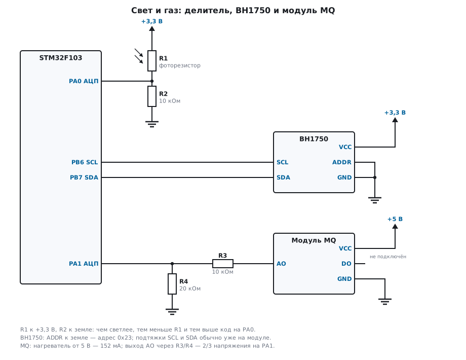
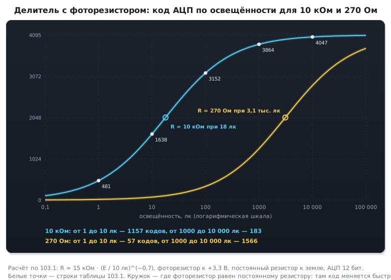
The resistance of a photoresistor falls with illuminance following a power law: R = R10 · (E / 10 lx)^(−γ), where R10 is the resistance at 10 lx and γ is the slope. The numbers for the example are R10 = 15 kΩ, γ = 0.7; every series has its own, and the spread between parts is large. The photoresistor goes to +3.3 V, a 10 kΩ resistor to ground, the midpoint to the ADC input: the brighter, the higher the code.
| Illuminance | Roughly | Resistance | ADC code |
|---|---|---|---|
| 1 lx | deep twilight | 75 kΩ | 481 |
| 10 lx | twilight | 15 kΩ | 1638 |
| 100 lx | very overcast day | 3.0 kΩ | 3152 |
| 1000 lx | overcast day | 597 Ω | 3864 |
| 10000 lx | daylight in the shade | 119 Ω | 4047 |
The divider compresses the bright end of the scale. From 1 to 10 lx the code moves 1157 steps, from 1000 to 10000 lx only 183. The divider is most sensitive where the photoresistor equals the fixed resistor: for 10 kΩ that is about 18 lx — a dimly lit room. For bright light the resistor is chosen smaller: with 270 Ω the range from 1000 to 10000 lx gets 1566 codes, but from 1 to 10 lx only 57 remain.
103.2 From code to lux
The conversion goes backwards: resistance from the code, illuminance from the resistance.
float ldr_lux(uint16_t code)
{
    if (code == 0)
        return 0.0f;
    if (code >= 4095)
        return -1.0f;
    float r = LDR_RF * (4095 - code) / code;
    return 10.0f * powf(r / LDR_R10, -1.0f / LDR_GAMMA);
}
The code for 100 lx converts back to 100.1 lx, for 1000 lx — to 998.4 lx: at 1000 lx one code is 0.66 % of the reading. The extreme codes are not illuminance but a fault. The function returns code 0 as 0 lx, but with this divider it is almost always an open photoresistor: even 0.01 lx gives a code of about 21. Code 4095 is a short, and the function answers −1.
A photoresistor is slow: it responds to light within tens of milliseconds, to darkness — longer. And R10 and γ are only known approximately. So it is good for a "dark — light" decision with hysteresis, and lux are measured more honestly with the BH1750.
103.3 BH1750: commands instead of registers
The BH1750 has no register map: every byte written is a command, and reading two bytes returns the last result, most significant byte first. The address is set by the ADDR pin: to ground — 0x23, to the supply — 0x5C. The module is powered from 3.3 V; the SDA and SCL pull-ups are usually already on it (section 95).
| Command | Code | What it does |
|---|---|---|
| power on | 0x01 | wait for a measurement command |
| reset | 0x07 | clear the result; only in the powered-on state |
| continuous, high resolution | 0x10 | measure without stopping, about 120 ms per measurement |
| one-time, high resolution | 0x20 | one measurement, then sleep |
int bh_start(uint32_t mt)
{
    const uint8_t cmd[4] = { BH_POWER_ON, BH_MT_HI(mt), BH_MT_LO(mt), BH_CONT_H };
    for (unsigned i = 0; i < 4; i++)
        if (!i2c_send(BH_ADDR, &cmd[i], 1))
            return 0;
    return 1;
}

int bh_read(uint32_t mt, uint32_t *lux_x10)
{
    uint8_t b[2];
    if (!i2c_recv(BH_ADDR, b, 2))
        return 0;
    *lux_x10 = bh_lux_x10((uint16_t)(b[0] << 8 | b[1]), mt);  /* старший байт первым */
    return 1;
}
Each command is a separate one-byte write. The model on the bus received exactly 0x01, 0x42, 0x65, 0x10, and the driver converted code 1000 into 833.3 lx: at an integration time of 69, illuminance is the code divided by 1.2. The first measurement is ready after 120 ms, at worst after 180 ms; anything read earlier is zero or an old value. Lamps on 50 Hz mains flicker at 100 Hz, and 120 ms holds exactly 12 periods — the flicker is averaged out.
103.4 Integration time
MTreg is the integration time: from 31 to 254, 69 by default. It is set with two commands: the upper three bits go into 0x40, the lower five into 0x60; for 69 that is 0x42 and 0x65. Lux per code is 69 / (1.2 · MTreg):
#define BH_MT_HI(mt) ((uint8_t)(0x40u | ((mt) >> 5)))
#define BH_MT_LO(mt) ((uint8_t)(0x60u | ((mt) & 0x1Fu)))

uint32_t bh_lux_x10(uint16_t raw, uint32_t mt)
{
    return ((uint32_t)raw * 6900u + 6u * mt) / (12u * mt);
}
| MTreg | Lux per code | Full scale | Measurement time |
|---|---|---|---|
| 31 | 1.85 | 121556.9 lx | about 54 ms |
| 69 | 0.83 | 54612.5 lx | about 120 ms |
| 254 | 0.23 | 14835.7 lx | about 442 ms |
Direct sunlight can be brighter than 54612 lx, and at MTreg 69 the code hits 65535: outdoors you set 31. In the dark it is the other way round: 254 gives 0.23 lx per code at the cost of almost half a second per measurement. The math is done in tenths of a lux with integers, with rounding: no FPU is needed, and the F103 does not have one anyway.
103.5 MQ: the heater first
The sensing layer of MQ sensors is tin oxide, and gas changes its resistance only while the layer is hot. The heater of the MQ-2 and MQ-135 is 33 Ω at 5 V: that is 152 mA and 0.76 W, more than everything else on the board. Hence the rules:
- power it from a 5 V rail that can handle an extra 152 mA; from 3.3 V the layer will not warm up, and the readings are meaningless;
- a new sensor is burned in for a day or longer, and after every power-up — for a few minutes: until the layer is warm, the readings drift;
- an MQ does not live on a battery: a 2000 mA·h battery is drained by one heater in 13 hours.
The MQ-7 and MQ-9 are also heated in cycles — high and low voltage in turn, as their documentation requires: there you cannot do without a switch on the heater.
103.6 Layer resistance and a divider to 3.3 V
The layer Rs and the module's load resistor RL form a divider from 5 V: the more gas, the lower Rs and the higher the voltage at the AO output. Hence Rs = RL · (Vc − Vout) / Vout. Every module has its own RL; its value is read from the marking on the board; in the example it is 10 kΩ:
| Module output | Rs |
|---|---|
| 0.5 V | 90 kΩ |
| 1.0 V | 40 kΩ |
| 2.5 V | 10 kΩ |
| 4.0 V | 2.5 kΩ |
The output goes up to 5 V, while the STM32 ADC input goes up to 3.3 V, and in analog mode the pin does not tolerate 5 V. Between them sits a 10 kΩ and 20 kΩ divider: the input gets 2/3 of the voltage, you can measure up to 4.95 V, and code 3309 is 4000 mV at the module output.
But the divider itself loads the output: its 30 kΩ is in parallel with RL, and 7.5 kΩ goes into the formula, not 10. Code 3309 means Rs = 1875 Ω, not 2500: with RL = 10 kΩ the resistance would come out 33.3 % higher than the real one.
#define MQ_RL      10000u               /* нагрузочный резистор модуля — по маркировке на плате */
#define MQ_DIV     30000u               /* делитель к АЦП нагружает выход */
#define MQ_RL_EFF  (MQ_RL * MQ_DIV / (MQ_RL + MQ_DIV))

uint32_t mq_rs(uint32_t vout_mv, uint32_t vc_mv, uint32_t rl_ohm)
{
    if (vout_mv == 0)
        return UINT32_MAX;              /* слой оборван или нагреватель холодный */
    if (vout_mv >= vc_mv)
        return 0;                       /* выход у питания: замыкание */
    return (uint32_t)((uint64_t)rl_ohm * (vc_mv - vout_mv) / vout_mv);
}
A divider of 10 and 20 kΩ is 6.7 kΩ at the ADC input: the sampling time needs to be longer (section 14). The module's digital output DO is a comparator with a trimmer resistor, usually with a pull-up to the module supply: at 5 V it is connected to a 5 V-tolerant pin, and not in analog mode.
103.7 Clean air and the alarm
A cheap MQ will not give you a concentration in ppm: the layer reacts to several gases at once, to humidity and to temperature, and every part has its own resistance in clean air. A ratio is more reliable: Rs relative to the resistance of the same sensor in clean air after warm-up. RL cancels out in the ratio: 2.5 V against 1.0 V is 25 % both with RL 10 kΩ and with 7.5 kΩ. The graphs in the documentation are usually plotted against R0 — the resistance at a reference gas concentration, not in clean air: before reading a concentration off them, check what they are referenced to.
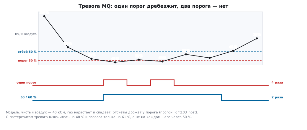
The alarm is switched on at one threshold and switched off at another, higher one:
int mq_alarm(int alarm, uint32_t rs, uint32_t r_air, uint32_t on_pct, uint32_t off_pct)
{
    uint32_t pct = (uint32_t)((uint64_t)rs * 100u / r_air);
    if (!alarm && pct < on_pct)
        return 1;
    if (alarm && pct > off_pct)
        return 0;
    return alarm;
}
Model: 40 kΩ in clean air, the gas rises and falls, and the samples jitter around the threshold — 100, 65, 52, 48, 51, 49, 57, 53, 61 and 75 % of clean air. An alarm with a single 50 % threshold toggles 4 times. With hysteresis — on below 50 %, off above 60 % — 2 times: it came on at 48 % and went off at 61 %.
103.8 Pitfalls
The photoresistor reads 0 or 4095. That is not light but an open or a short in the divider: there are no lux at the edges of the scale.
In the sun the BH1750 froze at 54612 lx. The code hit 65535 at MTreg 69. Reduce MTreg to 31.
The first BH1750 read is zero. It was read before the first measurement finished. After the command, wait 180 ms.
The BH1750 does not answer at address 0x23. ADDR is pulled to the supply — the address is 0x5C.
MQ readings drift for the first minutes. The layer has not warmed up. Do not trust samples after power-up; burn in a new sensor for a day.
The MQ's Rs is a third higher than it should be. You forgot that the divider to the ADC is in parallel with RL.
The MQ code is stuck at 4095, and neighbouring ADC channels are wrong. The module output goes to the input without a divider: more than 3.3 V on an analog input means current through the protection diodes, and it upsets the neighbouring channels.
The battery died in half a day. The MQ heater draws 152 mA nonstop.
103.9 Summary
- Photoresistor — a divider and a power law; with 10 kΩ, from 1 to 10 lx there are 1157 codes, from 1000 to 10000 lx — 183; the fixed resistor is chosen for the working range.
- Extreme ADC codes are a fault, not light.
- BH1750 — one-byte commands and a two-byte result: at MTreg 69 the code divided by 1.2 is lux; in the sun MTreg 31, in the dark — 254.
- MQ means a 152 mA heater: 5 V, warm-up, not from a battery.
- Rs is computed taking the ADC divider into account, the alarm — relative to clean air and with hysteresis.
Next: section 103а "MAX30102 pulse oximeter: photoplethysmogram over I2C, FIFO, pulse extraction and SpO₂ estimation — and why it is not a medical device" — pulse and the R ratio from light through a finger: the MAX30102 over I2C, the FIFO and processing on the F103; a teaching example, not a medical device.