 Embedded HandbookApps
103а. MAX30102 pulse oximeter: photoplethysmogram over I2C, FIFO, pulse extraction and SpO₂ estimation — and why it is not a medical device
In section 103 the BH1750 measured the light falling on the sensor. The MAX30102 shines the light itself — with a red and an infrared LED into a finger — and measures how much comes back. With every heartbeat there is a little more blood in the finger, and a little less light returns: this is the photoplethysmogram, PPG. The pulse is taken from it, and from the ratio of two colours comes what pulse oximeters turn into oxygen saturation of the blood, SpO₂. Here — how it works, what is inside the chip, how to connect it to the F103 and read the FIFO, how to pick out beats and count the rate, what the R ratio is and why without calibration on people it does not turn into percent, and what motion, light and finger pressure do to the signal.
This is a teaching example, not a medical device. The code and the numbers of this section were checked only on a model. It is not fit for diagnosis, monitoring of treatment or any decisions about health.
References: RM0008 (DocID13902 Rev 17): the pin mode table, p. 160;
AFIO_EXTICR3, p. 191; EXTI_FTSR, p. 211; master reception of more than two
bytes, method 2, pp. 762–763; reception of one byte, p. 764; I2C_CCR,
pp. 783–784; I2C_TRISE, p. 784. DocID13587 Rev 17 (STM32F103x8/xB):
PB6 — I2C1_SCL, PB7 — I2C1_SDA, both FT, PB5 not FT, p. 32; PB8 — FT,
p. 33; input thresholds, table 35, p. 62. There is no MAX30102 document in the
project: the address, registers, codes of rate, pulse width, range and current,
the behaviour of the FIFO, the flags and the INT pin are taken from the
manufacturer's documentation and built into the model — per the manufacturer's
documentation, not verified. Register numbers, fields and codes match the open
driver of the related MAX30101 (it also has a green LED) in Zephyr 4.4.2 on
disk, but that is not a document. So everything below checks that the driver
agrees with the model, not with the chip and certainly not with a finger. All
numbers come from running the driver _verify/ppg103b/max103b.c and the
processing ppg103b.c on a PC (gcc 12.2.0) with our own model of the MAX30102
as an I2C slave and a synthetic PPG in Python 3.11; the firmware was built with
armclang 6.24 for Cortex-M3.
What it is called in the documentation
Original Meaning photoplethysmography (PPG) how much light came back from tissue pulse oximeter, SpO₂ pulse oximeter; oxygen saturation of arterial blood AC / DC component pulsating / constant component perfusion index (PI) AC/DC, usually in percent ratio of ratios, R (AC/DC) of red over (AC/DC) of IR LED pulse amplitude ( LEDx_PA)LED current pulse width ( LED_PW)LED pulse width — also the integration time and the resolution ADC full-scale range ( SPO2_ADC_RGE)ADC range: the photocurrent at the top of the scale FIFO almost full ( A_FULL)the FIFO is almost full: interrupt FIFO rollover overwriting old samples when the FIFO is full ambient light cancellation (ALC) subtraction of ambient light motion artifact motion artifact refractory period after a beat no new one is searched for inter-beat interval (IBI) interval between beats
103а.1 Principle: light through a finger
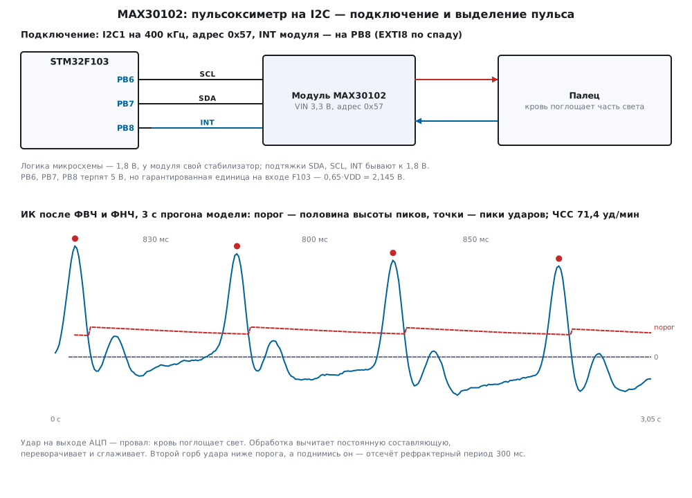
The LED shines into the finger, a photodiode next to it catches what scattered and came back. Most of the light is eaten by skin, muscle, bone and venous blood, and that part does not change from beat to beat — the constant component, DC. The arteries widen slightly with every beat, there is more blood in the light's path, and less light returns. This is the pulsating component, AC, and it is small: in the model the IR modulation depth is 2 % of the constant. At the ADC output a beat is not a spike but a dip: blood absorbs light.
One colour would be enough for the pulse. Two are needed for SpO₂: haemoglobin with oxygen and without it absorbs red and IR light differently. The ratio of AC to DC in each channel removes the LED brightness, finger thickness and skin colour — everything that presses both readings equally. The ratio of two such ratios
R = (AC_red / DC_red) / (AC_ir / DC_ir)
depends on what is in the blood. But how exactly — physics gives no ready formula: light scatters in tissue, the path differs for different colours, and the wavelengths differ between LEDs. The link from R to percent is taken by experiment on people — see 103а.5.
The light here is measured not in lux but as photocurrent in nanoamps, and not the room's illumination but the finger: ambient light is interference that the chip tries to subtract (103а.6).
103а.2 The chip: LEDs, ADC and a 32-sample FIFO
Per the manufacturer's documentation the MAX30102 contains red and IR LEDs with their own current sources, a photodiode, an ADC with ambient light subtraction, a die temperature sensor and a 32-sample FIFO. The bus address is 0x57 (the line byte 0xAE for write and 0xAF for read, 17.2). The registers needed here (numbers as in Zephyr's MAX30101 driver):
| Register | Number | What it holds |
|---|---|---|
INT_STATUS1 |
0x00 | A_FULL (bit 7), PPG_RDY (bit 6), ALC_OVF (bit 5), PWR_RDY (bit 0) |
INT_ENABLE1 |
0x02 | which flags pull INT low |
FIFO_WR_PTR, OVF_COUNTER, FIFO_RD_PTR |
0x04…0x06 | write pointer, lost count, read pointer |
FIFO_DATA |
0x07 | samples: 3 bytes per channel |
FIFO_CONFIG |
0x08 | SMP_AVE [7:5], FIFO_ROLLOVER_EN [4], FIFO_A_FULL [3:0] |
MODE_CONFIG |
0x09 | SHDN [7], RESET [6], MODE [2:0]: 2 — red only, 3 — SpO2 |
SPO2_CONFIG |
0x0A | ADC_RGE [6:5], SR [4:2], LED_PW [1:0] |
LED1_PA, LED2_PA |
0x0C, 0x0D | red and IR current |
PART_ID |
0xFF | 0x15 |
Three codes in SPO2_CONFIG decide almost everything:
| Code | 0 | 1 | 2 | 3 |
|---|---|---|---|---|
LED_PW: pulse |
69 µs, 15 bits | 118 µs, 16 bits | 215 µs, 17 bits | 411 µs, 18 bits |
ADC_RGE: top of scale |
2048 nA | 4096 nA | 8192 nA | 16384 nA |
SR: samples per second |
50 | 100 | 200 | 400 |
SR has eight codes: further 800, 1000, 1600 and 3200. A long pulse means more
collected light and more bits, but it is not compatible with every rate (per the
manufacturer's documentation). A sample always sits in 18 bits, aligned to the
top: at 15 bits the three lowest are zeros. The Zephyr driver shifts it right,
ours keeps it on the 18-bit scale, so the top of the scale is the same for all
widths: 262 143.
The LED current is a code from 0 to 255, per the manufacturer's documentation about 0.2 mA per unit; in the model exactly 0.2: 0x24 — 7.2 mA, 0xFF — 51 mA (the Zephyr driver description names the limit 50 mA). The current sets both the brightness and where in the ADC scale the constant component lands (103а.7).
Here — SpO2 mode (3), 100 samples per second, 411 µs and 18 bits, the 4096 nA
range — 15.625 pA per code unit, current 0x24 on both LEDs, no averaging in the
chip. FIFO_A_FULL = 15: INT goes low when 15 free places are left in the FIFO,
that is, when it holds 17 samples. Without FIFO_ROLLOVER_EN a full FIFO takes no
new samples but counts them in OVF_COUNTER (this is how the Zephyr driver
binding describes it too).
103а.3 Connecting to the F103 and initialisation
| Module pin | STM32F103 | Purpose |
|---|---|---|
| VIN | 3.3 V | module supply |
| GND | GND | ground |
| SCL | PB6 | I2C1 clock |
| SDA | PB7 | I2C1 data |
| INT | PB8 | interrupt, active low, open drain |
Per the manufacturer's documentation the MAX30102 logic runs from 1.8 V and the LEDs from 3.3 V and up. Modules carry their own 1.8 V regulator, and on some modules the SDA, SCL and INT pull-ups go to that 1.8 V rather than to 3.3 V — check your module's schematic (not verified). What this means for the F103 is seen in table 35 (DocID13587, p. 62): the guaranteed high level at an input is 0.65 × VDD, at 3.3 V that is 2.145 V, and it is tested in production. The lower thresholds — 1.546 V for FT pins and 1.833 V for ordinary ones — come from design simulation, not testing. A 1.8 V high is below the guaranteed level, and for an ordinary pin below even the simulated one. That is why INT goes to PB8 — it is FT (p. 33) — and not to the neighbouring PB5 without FT (p. 32). PB6 and PB7 are FT too (p. 32). Most reliable of all — pull-ups to 3.3 V or a level shifter (95а).
I2C1 — as in 15б.2: 400 kHz, CCR = F/S | 30, TRISE = 11. PB8 is an input
with pull-up (CNF = 10, MODE = 00, a one in ODR; RM0008, p. 160), EXTI8 on
the falling edge: in AFIO_EXTICR3 (p. 191) the code 0001 — port B, EXTI_FTSR
(p. 211) — falling edge:
/* INT: спад на PB8 — в FIFO 17 отсчётов */
void EXTI9_5_IRQHandler(void)
{
    EXTI->PR = 1u << 8;
    irq = 1;
}

static void irq_init(void)
{
    AFIO->EXTICR[2] = (AFIO->EXTICR[2] & ~0xFu) | 0x1u;     /* EXTI8 ← PB8 */
    EXTI->FTSR |= 1u << 8;
    EXTI->IMR |= 1u << 8;
    NVIC_EnableIRQ(EXTI9_5_IRQn);
}
Initialisation — check that the right chip is at the address, reset it, wait for the reset to finish, clear the power-on flag and configure. The mode is written last: samples start with it.
/* сброс, ожидание конца сброса, настройка; режим пишется последним — с него начинаются отсчёты */
int max_init(max_t *d, const max_cfg_t *c)
{
    uint8_t v = 0;
    int rc;
    d->leds = c->mode == MAX_MODE_SPO2 ? 2u : 1u;
    d->xfers = d->errors = d->lost = d->alc_ovf = 0;
    if ((rc = max_get(d, MAX_PART_ID, &v)) != MAX_OK)
        return rc;
    if (v != MAX_PART_ID_VAL)
        return MAX_E_ID;                                /* по адресу 0x57 не та микросхема */
    if ((rc = max_reg(d, MAX_MODE_CONFIG, MAX_MODE_RESET)) != MAX_OK)
        return rc;
    for (uint32_t i = 0;; i++) {                        /* RESET сбрасывается сам */
        max_port_delay_us(1000u);
        if ((rc = max_get(d, MAX_MODE_CONFIG, &v)) != MAX_OK)
            return rc;
        if (!(v & MAX_MODE_RESET))
            break;
        if (i + 1u >= MAX_RESET_TRIES)
            return MAX_E_RESET;
    }
    if ((rc = max_get(d, MAX_INT_STATUS1, &v)) != MAX_OK)  /* снять PWR_RDY — INT отпущен */
        return rc;
    /* без FIFO_ROLLOVER_EN: в полный FIFO новые отсчёты не пишутся, их считает OVF_COUNTER */
    if ((rc = max_reg(d, MAX_FIFO_CONFIG, (uint8_t)((c->ave & 7u) << 5 | (c->a_full & 0x0Fu)))) != MAX_OK)
        return rc;
    if ((rc = max_reg(d, MAX_SPO2_CONFIG, (uint8_t)((c->rge & 3u) << 5 | (c->sr & 7u) << 2 | (c->pw & 3u)))) != MAX_OK)
        return rc;
    if ((rc = max_reg(d, MAX_LED1_PA, c->led_red)) != MAX_OK)
        return rc;
    if ((rc = max_reg(d, MAX_LED2_PA, c->led_ir)) != MAX_OK)
        return rc;
    if ((rc = max_reg(d, MAX_INT_ENABLE1, MAX_INT_A_FULL)) != MAX_OK)
        return rc;
    return max_reg(d, MAX_MODE_CONFIG, (uint8_t)(c->mode & 7u));
}
In the model max_init is 10 exchanges: read PART_ID, 09 40 (reset), read
MODE_CONFIG, read INT_STATUS1, 08 0F, 0A 27, 0C 24, 0D 24, 02 80
and 09 03. 800 µs on the bus, together with the pause after reset — 1800 µs. A
foreign PART_ID (0x11 instead of 0x15) — refusal MAX_E_ID, −3. Reading
INT_STATUS1 is not superfluous: after power-up in the model INT is already
low — the PWR_RDY flag — and until it is read there will never be a falling
edge on PB8 (103а.7). After max_init INT is high.
103а.4 Reading the FIFO: pointers, overflow, bus time
The FIFO has two five-bit pointers: where the chip will write the next sample
and where it will be read from. Their difference modulo 32 is how many are
waiting. The trouble is that 32 modulo 32 is 0: the pointers are equal both for
an empty FIFO and for a full one. OVF_COUNTER helps tell them apart: if
samples were being lost, the FIFO is certainly full. All three registers are read
in one exchange — the register number grows after every byte:
/* сколько отсчётов ждёт в FIFO: указатели записи и чтения по 5 бит; равны — пусто или полно */
int max_fifo_count(max_t *d, uint32_t *n, uint32_t *ovf)
{
uint8_t reg = MAX_FIFO_WR_PTR, p[3]; /* WR_PTR, OVF_COUNTER, RD_PTR одним чтением */
int rc = xfer_done(d, max_port_xfer(d->addr, ®, 1, p, 3));
if (rc != MAX_OK)
return rc;
*ovf = p[1] & 0x1Fu;
*n = (uint32_t)(p[0] - p[2]) & (MAX_FIFO_DEPTH - 1u);
if (*n == 0u && *ovf != 0u)
*n = MAX_FIFO_DEPTH; /* отсчёты терялись — значит, FIFO полон */
return MAX_OK;
}
The samples themselves — in one long read of FIFO_DATA. Here the register
number does not grow: every 6 bytes (3 for red, 3 for IR) the chip takes the next
sample out of the FIFO. Bytes go most significant first, the meaningful ones are
the lower 18 bits:
/* всё, что есть в FIFO, одним чтением: по 3 байта на канал, в SpO2 сначала красный, потом ИК.
* lost — сколько отсчётов не поместилось: они были ПОСЛЕ прочитанных */
int max_read_fifo(max_t *d, uint32_t *red, uint32_t *ir, uint32_t maxn, uint32_t *got, uint32_t *lost)
{
uint8_t reg = MAX_FIFO_DATA, buf[MAX_FIFO_DEPTH * 6u];
uint32_t n, ovf, k = 3u * d->leds;
int rc;
*got = *lost = 0;
if ((rc = max_fifo_count(d, &n, &ovf)) != MAX_OK)
return rc;
if (n > maxn)
n = maxn;
*lost = ovf;
d->lost += ovf;
if (n == 0u)
return MAX_OK;
if ((rc = xfer_done(d, max_port_xfer(d->addr, ®, 1, buf, n * k))) != MAX_OK)
return rc;
for (uint32_t i = 0; i < n; i++) {
red[i] = max_unpack(&buf[i * k]);
ir[i] = d->leds == 2u ? max_unpack(&buf[i * k + 3u]) : 0u;
}
*got = n;
return MAX_OK;
}
OVF_COUNTER counts samples that did not fit — they came after the ones lying
in the FIFO. So the order is: first process what was read, then
ppg_skip(&ppg, n_lost) — shift the time count by the lost ones. The filters
will not fill the hole, but intervals between beats stay correct.
Reception on the F103. More than two bytes the F103 master receives by
method 2 (RM0008, pp. 762–763): when three bytes are left, wait for BTF, clear
ACK, read N−2, BTF again, STOP, read N−1 and after RXNE — N. One byte has
its own order (p. 764):
/* приём nrx байт после повторного старта: 1 байт — RM0008, с. 764; больше двух — способ 2, с. 762–763 */
static int rx_bytes(uint8_t *rx, uint32_t nrx)
{
    int rc;
    uint32_t i = 0;
    if (nrx == 1u) {
        I2C1->CR1 &= (uint16_t)~I2C_CR1_ACK;            /* ACK снять до сброса ADDR */
        (void)I2C1->SR2;
        I2C1->CR1 |= I2C_CR1_STOP;
        if ((rc = sr1_wait(I2C_SR1_RXNE)) != MAX_OK)
            return rc;
        rx[0] = (uint8_t)I2C1->DR;
        I2C1->CR1 |= I2C_CR1_ACK;
        return MAX_OK;
    }
    (void)I2C1->SR2;                                    /* ADDR снят, ACK = 1 */
    for (; i + 3u < nrx; i++) {
        if ((rc = sr1_wait(I2C_SR1_RXNE)) != MAX_OK)
            return rc;
        rx[i] = (uint8_t)I2C1->DR;
    }
    if ((rc = sr1_wait(I2C_SR1_BTF)) != MAX_OK)         /* осталось три: N−2 в DR, N−1 в сдвиговом, SCL прижат */
        return rc;
    I2C1->CR1 &= (uint16_t)~I2C_CR1_ACK;
    rx[i++] = (uint8_t)I2C1->DR;                        /* N−2; пошёл приём N с NACK */
    if ((rc = sr1_wait(I2C_SR1_BTF)) != MAX_OK)
        return rc;
    I2C1->CR1 |= I2C_CR1_STOP;
    rx[i++] = (uint8_t)I2C1->DR;                        /* N−1 */
    if ((rc = sr1_wait(I2C_SR1_RXNE)) != MAX_OK)
        return rc;
    rx[i] = (uint8_t)I2C1->DR;                          /* N */
    I2C1->CR1 |= I2C_CR1_ACK;
    return MAX_OK;
}
Bus time. In the model the interrupt comes every 17 samples, once every
170 ms, and the handler makes three exchanges: INT_STATUS1, three pointers and
102 bytes of samples.
| Exchange | SCL clocks | 400 kHz | 100 kHz |
|---|---|---|---|
INT_STATUS1, 1 byte |
39 | ||
| pointers, 3 bytes | 57 | ||
| 17 samples, 102 bytes | 948 | ||
| whole interrupt | 1044 | 2610 µs | 10 440 µs |
| bus share | 1.54 % | 6.14 % |
One sample is 54 clocks, 135 µs at 400 kHz. Over 60 s of the main run the handler fired 352 times, the bus was busy 1.53 % of the time. After the interrupt the FIFO still has 15 free places — 150 ms to respond.
Polling instead of an interrupt. If the FIFO is read on a timer, the period decides everything. In the model 60 s at 72 beats per minute, the heart rate error is the mean over reports:
| Polling period | Reads | Samples lost | OVF counted |
Heart rate error, with shift / without |
|---|---|---|---|---|
| 170 ms | 352 | 0 | 0 | 0.42 / 0.42 bpm |
| 250 ms | 239 | 0 | 0 | 0.43 / 0.43 bpm |
| 320 ms | 187 | 2977 | 2884 | 1.96 / 51.44 bpm |
| 330 ms | 181 | 182 | 182 | 0.40 / 1.97 bpm |
| 400 ms | 150 | 1201 | 1201 | 0.47 / 17.66 bpm |
| 1000 ms | 59 | 4013 | 1829 | 46.45 / 28.27 bpm |
320 ms is exactly 32 samples, and here is the equal-pointer trap: the driver sees
0, and every second read is empty (103а.7). 400 ms without the time shift gives
88.2 beats per minute instead of 71.4: the intervals are shorter because lost
samples dropped out of the count. At 1000 ms even the shift does not help:
OVF_COUNTER is five bits, it does not count above 31. An interrupt on A_FULL
knows none of these troubles.
103а.5 Processing: pulse, rate and the R ratio
The chain for each channel is as in sections 81 and 81а, only in integers (the F103 has no FPU). High-pass: the constant component is tracked by an exponential average with weight 1/32 and subtracted — cutoff about 100 / (2π · 32) = 0.5 Hz at 100 samples per second. The result is flipped so that a beat goes up. Low-pass: a moving average over 8 samples — delay 3.5 samples, first zero at 12.5 Hz:
/* один канал: ФВЧ (минус медленное среднее), переворот, ФНЧ (среднее по 8) */
static int32_t ch_step(ppg_ch_t *c, uint32_t x, uint32_t pos, int first)
{
    int32_t xq = (int32_t)(x << PPG_Q);
    if (first)
        c->dc = xq;
    c->dc += (xq - c->dc) / (1 << PPG_DC_SHIFT);
    int32_t ac = c->dc / (1 << PPG_Q) - (int32_t)x;     /* кровь поглощает свет: удар — провал, переворачиваем */
    c->sum += ac - c->ma[pos];
    c->ma[pos] = ac;
    c->y = c->sum / (int32_t)PPG_MA_N;
    if (c->y < c->lo)
        c->lo = c->y;
    if (c->y > c->hi)
        c->hi = c->y;
    return c->y;
}
Peaks. The threshold is half the peak height; the height is forgotten by 1/256 per sample (in 2.56 s — about e times), so that after a strong beat the threshold comes back down. While the signal is above the threshold, the maximum is searched for; once it drops below — this is a beat candidate:
    p->amp -= p->amp / 256;                             /* высота пиков забывается за несколько секунд */
    p->thr = p->amp / 2;
    if (y > p->thr && y > 0) {
        if (!p->above || y > p->cand_y) {
            p->cand = idx;
            p->cand_y = y;
        }
        p->above = 1;
        return 0;
    }
    if (!p->above)
        return 0;
    p->above = 0;                                       /* спуск под порог: пик позади */
    return accept(p);
A candidate closer than 300 ms to the previous beat is not a beat (the refractory period: 200 beats per minute is 300 ms): this cuts off the second hump of the same wave and small interference. An interval longer than 2 s — the pulse is lost, start over. The heart rate is 60 · fs divided by the median of the last 8 intervals; the median does not fear one extra or one missed beat:
/* кандидат прошёл: интервал, ЧСС, R и перфузия по размаху с прошлого удара */
static int accept(ppg_t *p)
{
    uint32_t d = p->cand - p->last;
    if (p->have_last && d < p->refract)
        return 0;                                       /* второй горб того же удара или помеха */
    p->amp += (p->cand_y - p->amp) / 4;
    int32_t ac_r = p->red.hi - p->red.lo, ac_i = p->ir.hi - p->ir.lo;
    int32_t dc_r = p->red.dc / (1 << PPG_Q), dc_i = p->ir.dc / (1 << PPG_Q);
    if (p->have_last && d <= p->ibi_max) {
        push_last(p->ibi, &p->nibi, d);
        if (ac_i > 0 && ac_r > 0 && dc_r > 0 && dc_i > 0) {
            push_last(p->rr, &p->nr, (uint32_t)((uint64_t)ac_r * (uint32_t)dc_i * 1000u / ((uint64_t)ac_i * (uint32_t)dc_r)));
            p->pi100 = (uint32_t)((uint64_t)ac_i * 10000u / (uint32_t)dc_i);
        }
        if (p->nibi >= 3u) {
            uint32_t m = ppg_median(p->ibi, p->nibi);
            p->hr10 = (600u * p->fs + m / 2u) / m;
            p->r1000 = ppg_median(p->rr, p->nr);
        }
    } else {
        p->nibi = p->nr = 0;                            /* пауза больше 2 с: всё сначала */
        p->hr10 = p->r1000 = 0;
    }
    p->last = p->cand;
    p->have_last = 1;
    p->beats++;
    p->red.lo = p->red.hi = p->red.y;
    p->ir.lo = p->ir.hi = p->ir.y;
    return 1;
}
A run on a synthetic PPG. In the model: 72 beats per minute, intervals wander by 3 %, breathing at 0.25 Hz, noise, model R 0.6; beats are counted from the 5th second. The first heart rate estimate comes 4.24 s after the samples start (a second for the filters and three intervals). In 60 s 65 beats out of 65 were found plus one extra, the beat peak is found 30 ms later than the real one (the filters), and the beat itself is accepted another 60–70 ms later — when the signal drops below the threshold. The mean heart rate error is 0.52 beats per minute, the largest — 1.64.
| Model heart rate | First estimate | Found | Extra | Error mean / largest |
|---|---|---|---|---|
| 45 bpm | 6.28 s | 41 of 41 | 0 | 0.28 / 0.75 bpm |
| 72 bpm | 4.41 s | 66 of 66 | 1 | 0.38 / 1.52 bpm |
| 120 bpm | 2.71 s | 110 of 110 | 0 | 1.06 / 3.75 bpm |
| 180 bpm | 2.20 s | 162 of 163 | 2 | 1.84 / 8.1 bpm |
At 180 beats the interval is 333 ms, close to the refractory 300 ms, and 94.4 %
of reports stayed within 5 beats per minute. If the finger is not placed at once:
while it is absent, the IR constant in the model is 2396 units, below the
PPG_FINGER_MIN threshold, and processing stays silent with the "no finger" flag;
the finger was placed at 2.99 s, the first heart rate came at 7.47 s.
The R ratio. On every beat the processing takes the signal swing since the previous beat (this is AC) and the constant component (DC) in both channels and computes R × 1000 in integers, the report is the median of the last 8 beats. In the model R is just a parameter: how many times the red modulation depth exceeds the IR one.
| Model R | 0.4 | 0.6 | 0.8 | 1.0 | 1.2 |
|---|---|---|---|---|---|
| R from the run, median | 0.415 | 0.606 | 0.804 | 1.007 | 1.206 |
| spread of reports | 0.395…0.437 | 0.593…0.629 | 0.789…0.819 | 0.986…1.023 | 1.184…1.222 |
R follows the model, and the filters hardly spoil it: they are the same in both channels. The perfusion index fares worse: 1.69 % from the run against 2 % in the model — the low-pass filter cuts the top of the beat.
Why not percent. A pulse oximeter turns R into SpO₂ by a calibration curve that is taken on people for its own design: volunteers' blood saturation is varied, the device readings are compared with an analysis of arterial blood, and the dependence is built. It is specific to each pair of LEDs, housing and place on the body. The "R → %" formulas that circulate in examples were not taken for your module, and they are absent from this section on purpose. In the model R is a number invented by the model, and any percent from it would be fiction. A medical pulse oximeter also means testing, registration and quality control. This code has none of that: it shows how the processing works and is not fit for assessing health.
103а.6 Motion, ambient light and finger pressure
Motion. In the model the finger moves during 20–30 s and 40–45 s: oscillations at 0.9, 1.7 and 2.9 Hz, in the same band as the pulse and larger than it in swing.
| Segment | Found | Extra | Error mean / largest | Within 5 bpm |
|---|---|---|---|---|
| motion and 4 s after | 23 of 27 | 11 | 13.25 / 21.86 bpm | 35.3 % |
| rest | 38 of 38 | 0 | 0.40 / 2.48 bpm | 100 % |
A filter will not remove motion: it sits where the pulse is. Worse, R during motion is 1.008 against 0.604 at rest. In the model motion changes both channels by the same share, and equal shares give R around 1 — a value that means nothing except "the finger is moving". In practice processing needs a signal quality estimate (for example an accelerometer nearby, section 99) and the right to say "don't know".
Ambient light. Per the manufacturer's documentation the chip measures the
light without the LED before each pulse and subtracts it — as long as it stays
within a limit, otherwise it sets ALC_OVF. In the model a lamp flickers at
100.4 Hz, the limit is 4000 nA (a model assumption).
| Ambient light | ALC_OVF |
Beats found | Heart rate |
|---|---|---|---|
| none | 0 of 352 reads | 65 of 65 | error 0.41 bpm |
| 2000 nA | 0 of 352 | 65 of 65 | error 0.41 bpm |
| 5000 nA | 245 of 352 | 22 of 65 | no estimate at all |
While subtraction copes, the light is not visible at all. Beyond the limit the
lamp flicker passes into the samples and drowns the pulse. The driver counts the
ALC_OVF flag (dev.alc_ovf) — on it the firmware can say "shield the finger
from light".
Pressure. Pressed hard — blood is squeezed out, there is less pulsating component. In the model pressure reduces the modulation depth:
| Modulation depth | Perfusion index from the run | Found | Extra | Error mean / largest |
|---|---|---|---|---|
| as is | 1.66 % | 65 of 65 | 1 | 0.51 / 1.71 bpm |
| × 0.3 | 0.50 % | 64 of 65 | 5 | 1.06 / 15.63 bpm |
| × 0.1 | 0.15 % | 39 of 65 | 13 | 27.87 / 58.27 bpm |
At ×0.1 the pulse drowns in breathing and noise. Light pressure is the opposite trouble: the finger moves and lets light in from the side — the two previous cases. The perfusion index is the simplest quality estimate: very small — do not trust the readings.
103а.7 Pitfalls
Samples jump, twice as many beats as there are. The byte order is mixed up:
the low byte taken for the high one. In the model the IR value became 54 273
instead of 119 936, in 30 s 74 "beats" were found against 29 real ones, and the
heart rate came out 166.7 instead of 71.5. Most significant byte first —
max_unpack.
The heart rate is too high when polling on a timer. The FIFO overflows,
samples are lost, and the time count does not know it: polling every 400 ms —
88.2 beats per minute instead of 71.4. Read on A_FULL or shift time by
OVF_COUNTER (103а.4). The shift helps as long as no more than 31 samples are
lost per read: in the model 330 and 400 ms — yes, 1000 ms — no.
The FIFO holds 32 samples, but the driver sees 0. The pointers are equal: in
the model after 32 samples WR_PTR = RD_PTR = 0 and OVF_COUNTER = 0. Two more
samples — and OVF_COUNTER = 2, then the driver reads 32. Do not wait for a full
FIFO: interrupt at 17.
The constant hit the top of the scale, no beats. The LED current is too large for the range:
| Current | Range | IR constant in the model | Saturation | Beats found in 30 s |
|---|---|---|---|---|
| 0x10, 3.2 mA | 4096 nA | 53 248 | no | 30 of 30 |
| 0x24, 7.2 mA | 4096 nA | 119 808 | no | 30 of 30 |
| 0x40, 12.8 mA | 4096 nA | 212 992 | no | 30 of 30 |
| 0x50, 16 mA | 4096 nA | 266 240 | yes | 23 of 30 |
| 0xFF, 51 mA | 4096 nA | 848 640 | yes | 0 of 30 |
| 0xFF, 51 mA | 16384 nA | 212 160 | no | 30 of 30 |
There is no scale above 262 143: the top of the beat is cut off, at 0xFF
everything is. The processing sets PPG_F_SAT. The current is chosen so that the
constant sits roughly in the middle of the scale, or a wider range is taken.
R around 1.67 instead of 0.6. The channels are swapped: the first three bytes of a sample are red, the second three IR. In the model with swapped channels R = 1.669 — almost exactly 1 / 0.6 = 1.667.
The module does not answer or INT is not read. Module pull-ups to 1.8 V are below the guaranteed F103 high level of 2.145 V (103а.3). The INT pin — on an FT pin, and better pull-ups to 3.3 V.
No interrupts at all. INT has been low since power-up (PWR_RDY) or since
last time, while EXTI catches only a falling edge. max_init reads
INT_STATUS1; the firmware, besides the interrupt flag, also checks the PB8 level
itself.
The finger is placed — the first seconds are silent. That is how it should be: a second for the filters and three intervals for the median, in the model the first heart rate comes after 4.24 s.
103а.8 Summary
- The MAX30102 is red and IR LEDs, a photodiode, an ADC up to 18 bits and a FIFO of 32 samples over I2C, address 0x57; the register map is per the manufacturer's documentation and Zephyr's MAX30101 driver.
- Here: SpO2, 100 samples per second, 411 µs, 4096 nA (15.625 pA per unit), 7.2 mA; INT at 17 samples — once every 170 ms, 2610 µs at 400 kHz, 1.54 % of the bus.
- The module logic is 1.8 V: the guaranteed F103 high level is 2.145 V; INT — on an FT pin (PB8), pull-ups — to 3.3 V.
- FIFO: the pointers are equal for both empty and full; lost samples — by
OVF_COUNTER(up to 31), shift time after the ones read. - Processing: high-pass about 0.5 Hz, low-pass over 8 samples, threshold — half the peak height, refractory period 300 ms, median of 8 intervals. In the model — 65 beats of 65, heart rate error 0.52 beats per minute, first estimate after 4.24 s.
- R in the model repeats the model parameter (0.606 at 0.6), with motion it is pulled toward 1. Without calibration on people R does not turn into SpO₂ percent.
- A teaching example, not a medical device: do not use it for diagnosis or decisions about health.
Full sources
max103b.h — registers, bits, codes, the port and the MAX30102 driver functions.
/* max103b.h — раздел 103а: драйвер MAX30102 (красный и ИК светодиоды, фотодиод, АЦП, FIFO) по I2C
 * без регистров микроконтроллера. Драйвер говорит с микросхемой только через две функции порта
 * (max_port_*): в прошивке fw103b.c их делает I2C1 STM32F103, в стенде host103b.c — модель model103b.py.
 * Карта регистров и биты — по документации производителя; документа в проекте нет, номера регистров и
 * поля совпадают с открытым драйвером родственной MAX30101 в Zephyr 4.4.2; с микросхемой не сверено. */
#ifndef MAX103B_H
#define MAX103B_H
#include <stdint.h>

/* ── регистры ─────────────────────────────────────────────────────────── */
#define MAX_INT_STATUS1   0x00u         /* чтение снимает флаги и отпускает INT */
#define MAX_INT_ENABLE1   0x02u
#define MAX_FIFO_WR_PTR   0x04u         /* 0x04…0x06 — запись, переполнение, чтение: читаются подряд */
#define MAX_OVF_COUNTER   0x05u
#define MAX_FIFO_RD_PTR   0x06u
#define MAX_FIFO_DATA     0x07u         /* номер регистра при чтении не растёт: каждые 3 байта — следующий канал */
#define MAX_FIFO_CONFIG   0x08u         /* SMP_AVE [7:5], FIFO_ROLLOVER_EN [4], FIFO_A_FULL [3:0] */
#define MAX_MODE_CONFIG   0x09u         /* SHDN [7], RESET [6], MODE [2:0] */
#define MAX_SPO2_CONFIG   0x0Au         /* ADC_RGE [6:5], SR [4:2], LED_PW [1:0] */
#define MAX_LED1_PA       0x0Cu         /* ток красного светодиода */
#define MAX_LED2_PA       0x0Du         /* ток ИК светодиода */
#define MAX_PART_ID       0xFFu

/* ── биты ─────────────────────────────────────────────────────────────── */
#define MAX_INT_A_FULL    0x80u         /* в FIFO осталось FIFO_A_FULL свободных мест */
#define MAX_INT_PPG_RDY   0x40u         /* новый отсчёт */
#define MAX_INT_ALC_OVF   0x20u         /* вычитание внешнего света упёрлось в предел */
#define MAX_INT_PWR_RDY   0x01u         /* питание появилось */
#define MAX_MODE_SHDN     0x80u
#define MAX_MODE_RESET    0x40u         /* сам сбрасывается в 0 по окончании */
#define MAX_MODE_HR       0x02u         /* только красный */
#define MAX_MODE_SPO2     0x03u         /* красный и ИК */
#define MAX_FIFO_ROLLOVER 0x10u

#define MAX_ADDR          0x57u         /* семибитный: 0xAE запись, 0xAF чтение */
#define MAX_PART_ID_VAL   0x15u
#define MAX_FIFO_DEPTH    32u
#define MAX_FULL_SCALE    0x3FFFFu      /* 18 бит; при 15…17 битах младшие биты — нули */
#define MAX_RESET_TRIES   10u

enum { MAX_OK = 0, MAX_E_NACK = -1, MAX_E_BUS = -2, MAX_E_ID = -3, MAX_E_RESET = -4 };

typedef struct {
    uint8_t mode;                       /* MAX_MODE_HR или MAX_MODE_SPO2 */
    uint8_t sr;                         /* частота отсчётов, код 0…7: 50, 100, 200, 400, 800, 1000, 1600, 3200 Гц */
    uint8_t pw;                         /* ширина импульса, код 0…3: 69, 118, 215, 411 мкс — 15…18 бит */
    uint8_t rge;                        /* диапазон АЦП, код 0…3: 2048, 4096, 8192, 16384 нА */
    uint8_t ave;                        /* усреднение в микросхеме, код 0…5: 1…32 отсчёта */
    uint8_t a_full;                     /* прерывание, когда в FIFO осталось столько свободных мест */
    uint8_t led_red, led_ir;            /* ток светодиодов, код 0…255 */
} max_cfg_t;

typedef struct {
    uint8_t addr;
    uint8_t leds;                       /* каналов в отсчёте: 1 (HR) или 2 (SpO2) */
    uint8_t status;                     /* последний INT_STATUS1 */
    uint32_t xfers, errors;             /* обменов по I2C и ошибок */
    uint32_t lost;                      /* отсчётов потеряно — по OVF_COUNTER */
    uint32_t alc_ovf;                   /* сколько раз внешний свет не вычелся */
} max_t;

/* ── порт: в прошивке — I2C1, в стенде — строки к модели ──────────────── */
/* ntx байт записи, затем (если nrx) повторный старт и nrx байт чтения; 0, MAX_E_NACK или MAX_E_BUS */
int max_port_xfer(uint8_t addr7, const uint8_t *tx, uint32_t ntx, uint8_t *rx, uint32_t nrx);
void max_port_delay_us(uint32_t us);

/* ── драйвер ──────────────────────────────────────────────────────────── */
int max_reg(max_t *d, uint8_t reg, uint8_t v);
int max_get(max_t *d, uint8_t reg, uint8_t *v);
int max_init(max_t *d, const max_cfg_t *c);
int max_service(max_t *d);
int max_fifo_count(max_t *d, uint32_t *n, uint32_t *ovf);
uint32_t max_unpack(const uint8_t *b);
int max_read_fifo(max_t *d, uint32_t *red, uint32_t *ir, uint32_t maxn, uint32_t *got, uint32_t *lost);

#endif
max103b.c — the driver: reset and setup, INT flags, FIFO pointers, reading samples.
/* max103b.c — раздел 103а: драйвер MAX30102 по I2C. Один и тот же файл собирается в прошивку (armclang,
* Cortex-M3) и в стенд на компьютере (gcc): микроконтроллера он не знает, только порт max_port_*. */
#include "max103b.h"
static int xfer_done(max_t *d, int rc)
{
d->xfers++;
if (rc)
d->errors++;
return rc;
}
int max_reg(max_t *d, uint8_t reg, uint8_t v)
{
uint8_t b[2] = {reg, v};
return xfer_done(d, max_port_xfer(d->addr, b, 2, 0, 0));
}
int max_get(max_t *d, uint8_t reg, uint8_t *v)
{
return xfer_done(d, max_port_xfer(d->addr, ®, 1, v, 1));
}
/* сброс, ожидание конца сброса, настройка; режим пишется последним — с него начинаются отсчёты */
int max_init(max_t *d, const max_cfg_t *c)
{
uint8_t v = 0;
int rc;
d->leds = c->mode == MAX_MODE_SPO2 ? 2u : 1u;
d->xfers = d->errors = d->lost = d->alc_ovf = 0;
if ((rc = max_get(d, MAX_PART_ID, &v)) != MAX_OK)
return rc;
if (v != MAX_PART_ID_VAL)
return MAX_E_ID; /* по адресу 0x57 не та микросхема */
if ((rc = max_reg(d, MAX_MODE_CONFIG, MAX_MODE_RESET)) != MAX_OK)
return rc;
for (uint32_t i = 0;; i++) { /* RESET сбрасывается сам */
max_port_delay_us(1000u);
if ((rc = max_get(d, MAX_MODE_CONFIG, &v)) != MAX_OK)
return rc;
if (!(v & MAX_MODE_RESET))
break;
if (i + 1u >= MAX_RESET_TRIES)
return MAX_E_RESET;
}
if ((rc = max_get(d, MAX_INT_STATUS1, &v)) != MAX_OK) /* снять PWR_RDY — INT отпущен */
return rc;
/* без FIFO_ROLLOVER_EN: в полный FIFO новые отсчёты не пишутся, их считает OVF_COUNTER */
if ((rc = max_reg(d, MAX_FIFO_CONFIG, (uint8_t)((c->ave & 7u) << 5 | (c->a_full & 0x0Fu)))) != MAX_OK)
return rc;
if ((rc = max_reg(d, MAX_SPO2_CONFIG, (uint8_t)((c->rge & 3u) << 5 | (c->sr & 7u) << 2 | (c->pw & 3u)))) != MAX_OK)
return rc;
if ((rc = max_reg(d, MAX_LED1_PA, c->led_red)) != MAX_OK)
return rc;
if ((rc = max_reg(d, MAX_LED2_PA, c->led_ir)) != MAX_OK)
return rc;
if ((rc = max_reg(d, MAX_INT_ENABLE1, MAX_INT_A_FULL)) != MAX_OK)
return rc;
return max_reg(d, MAX_MODE_CONFIG, (uint8_t)(c->mode & 7u));
}
/* обработчик INT: прочитать INT_STATUS1 — флаги снимаются, вывод отпускается */
int max_service(max_t *d)
{
int rc = max_get(d, MAX_INT_STATUS1, &d->status);
if (rc == MAX_OK && (d->status & MAX_INT_ALC_OVF))
d->alc_ovf++;
return rc;
}
/* сколько отсчётов ждёт в FIFO: указатели записи и чтения по 5 бит; равны — пусто или полно */
int max_fifo_count(max_t *d, uint32_t *n, uint32_t *ovf)
{
uint8_t reg = MAX_FIFO_WR_PTR, p[3]; /* WR_PTR, OVF_COUNTER, RD_PTR одним чтением */
int rc = xfer_done(d, max_port_xfer(d->addr, ®, 1, p, 3));
if (rc != MAX_OK)
return rc;
*ovf = p[1] & 0x1Fu;
*n = (uint32_t)(p[0] - p[2]) & (MAX_FIFO_DEPTH - 1u);
if (*n == 0u && *ovf != 0u)
*n = MAX_FIFO_DEPTH; /* отсчёты терялись — значит, FIFO полон */
return MAX_OK;
}
/* три байта канала: старший первым, значащие 18 младших бит */
uint32_t max_unpack(const uint8_t *b)
{
return ((uint32_t)b[0] << 16 | (uint32_t)b[1] << 8 | b[2]) & MAX_FULL_SCALE;
}
/* всё, что есть в FIFO, одним чтением: по 3 байта на канал, в SpO2 сначала красный, потом ИК.
* lost — сколько отсчётов не поместилось: они были ПОСЛЕ прочитанных */
int max_read_fifo(max_t *d, uint32_t *red, uint32_t *ir, uint32_t maxn, uint32_t *got, uint32_t *lost)
{
uint8_t reg = MAX_FIFO_DATA, buf[MAX_FIFO_DEPTH * 6u];
uint32_t n, ovf, k = 3u * d->leds;
int rc;
*got = *lost = 0;
if ((rc = max_fifo_count(d, &n, &ovf)) != MAX_OK)
return rc;
if (n > maxn)
n = maxn;
*lost = ovf;
d->lost += ovf;
if (n == 0u)
return MAX_OK;
if ((rc = xfer_done(d, max_port_xfer(d->addr, ®, 1, buf, n * k))) != MAX_OK)
return rc;
for (uint32_t i = 0; i < n; i++) {
red[i] = max_unpack(&buf[i * k]);
ir[i] = d->leds == 2u ? max_unpack(&buf[i * k + 3u]) : 0u;
}
*got = n;
return MAX_OK;
}
ppg103b.h — processing parameters and its state.
/* ppg103b.h — раздел 103а: обработка фотоплетизмограммы целыми числами (у F103 нет FPU).
 * Вход — отсчёты красного и ИК каналов MAX30102; выход — удары, ЧСС, отношение R и индекс перфузии.
 * Учебный пример: не медицинское изделие, для диагностики не годится. */
#ifndef PPG103B_H
#define PPG103B_H
#include <stdint.h>

#define PPG_DC_SHIFT   5u               /* ФВЧ: постоянная составляющая — среднее с весом 1/32 */
#define PPG_MA_N       8u               /* ФНЧ: скользящее среднее по 8 отсчётам */
#define PPG_Q          8u               /* постоянная составляющая хранится ×256 */
#define PPG_REFRACT_MS 300u             /* после удара 300 мс новых не ищем: это 200 ударов в минуту */
#define PPG_IBI_MAX_MS 2000u            /* интервал длиннее 2 с — пульс потерян, считать заново */
#define PPG_WARM_MS    1000u            /* первую секунду фильтры выходят на режим */
#define PPG_IBI_N      8u               /* ЧСС и R — медиана последних 8 ударов */
#define PPG_FINGER_MIN 20000u           /* постоянная ИК меньше — пальца нет */
#define PPG_SAT        0x3FF00u         /* отсчёт у верха шкалы 18 бит — насыщение */

enum { PPG_F_NOFINGER = 1, PPG_F_SAT = 2 };

typedef struct {
    int32_t dc;                         /* постоянная составляющая ×256 */
    int32_t ma[PPG_MA_N], sum;          /* окно скользящего среднего */
    int32_t y;                          /* пульсирующая составляющая, перевёрнута: удар — вверх */
    int32_t lo, hi;                     /* размах y с прошлого удара */
} ppg_ch_t;

typedef struct {
    ppg_ch_t red, ir;
    uint32_t fs, n, pos, start;         /* частота; номер отсчёта (с потерянными); место в окне; начало */
    uint32_t refract, ibi_max, warm;    /* в отсчётах */
    int32_t amp, thr;                   /* высота пиков и порог — её половина */
    int above, have_last, started;
    uint32_t cand, last;                /* кандидат в удары и последний удар — номера отсчётов */
    int32_t cand_y;
    uint32_t ibi[PPG_IBI_N], rr[PPG_IBI_N], nibi, nr;
    uint32_t beats, flags;
    uint32_t hr10;                      /* ЧСС ×10, 0 — оценки нет */
    uint32_t r1000;                     /* R = (AC_red/DC_red)/(AC_ir/DC_ir) ×1000 */
    uint32_t pi100;                     /* AC/DC ИК в сотых долях процента */
} ppg_t;

void ppg_init(ppg_t *p, uint32_t fs);
int ppg_push(ppg_t *p, uint32_t red, uint32_t ir);
void ppg_skip(ppg_t *p, uint32_t n);
uint32_t ppg_median(const uint32_t *v, uint32_t n);

#endif
ppg103b.c — processing: high-pass, low-pass, peaks, heart rate, the R ratio and the perfusion index.
/* ppg103b.c — раздел 103а: ФВЧ, ФНЧ, пики с адаптивным порогом и рефрактерным периодом, ЧСС по
 * интервалам и отношение R. Тот же файл — в прошивке (armclang, Cortex-M3) и в стенде на компьютере (gcc).
 * Учебный пример: не медицинское изделие, для диагностики не годится. */
#include "ppg103b.h"

void ppg_init(ppg_t *p, uint32_t fs)
{
    *p = (ppg_t){0};
    p->fs = fs;
    p->refract = fs * PPG_REFRACT_MS / 1000u;
    p->ibi_max = fs * PPG_IBI_MAX_MS / 1000u;
    p->warm = fs * PPG_WARM_MS / 1000u;
}

/* медиана до 8 чисел: вставками в копию */
uint32_t ppg_median(const uint32_t *v, uint32_t n)
{
    uint32_t s[PPG_IBI_N];
    if (n == 0u)
        return 0;
    for (uint32_t i = 0; i < n; i++) {
        uint32_t j = i;
        for (; j > 0u && s[j - 1u] > v[i]; j--)
            s[j] = s[j - 1u];
        s[j] = v[i];
    }
    return s[n / 2u];
}

/* один канал: ФВЧ (минус медленное среднее), переворот, ФНЧ (среднее по 8) */
static int32_t ch_step(ppg_ch_t *c, uint32_t x, uint32_t pos, int first)
{
    int32_t xq = (int32_t)(x << PPG_Q);
    if (first)
        c->dc = xq;
    c->dc += (xq - c->dc) / (1 << PPG_DC_SHIFT);
    int32_t ac = c->dc / (1 << PPG_Q) - (int32_t)x;     /* кровь поглощает свет: удар — провал, переворачиваем */
    c->sum += ac - c->ma[pos];
    c->ma[pos] = ac;
    c->y = c->sum / (int32_t)PPG_MA_N;
    if (c->y < c->lo)
        c->lo = c->y;
    if (c->y > c->hi)
        c->hi = c->y;
    return c->y;
}

static void push_last(uint32_t *v, uint32_t *n, uint32_t x)
{
    if (*n == PPG_IBI_N) {
        for (uint32_t i = 1; i < PPG_IBI_N; i++)
            v[i - 1u] = v[i];
        (*n)--;
    }
    v[(*n)++] = x;
}

/* кандидат прошёл: интервал, ЧСС, R и перфузия по размаху с прошлого удара */
static int accept(ppg_t *p)
{
    uint32_t d = p->cand - p->last;
    if (p->have_last && d < p->refract)
        return 0;                                       /* второй горб того же удара или помеха */
    p->amp += (p->cand_y - p->amp) / 4;
    int32_t ac_r = p->red.hi - p->red.lo, ac_i = p->ir.hi - p->ir.lo;
    int32_t dc_r = p->red.dc / (1 << PPG_Q), dc_i = p->ir.dc / (1 << PPG_Q);
    if (p->have_last && d <= p->ibi_max) {
        push_last(p->ibi, &p->nibi, d);
        if (ac_i > 0 && ac_r > 0 && dc_r > 0 && dc_i > 0) {
            push_last(p->rr, &p->nr, (uint32_t)((uint64_t)ac_r * (uint32_t)dc_i * 1000u / ((uint64_t)ac_i * (uint32_t)dc_r)));
            p->pi100 = (uint32_t)((uint64_t)ac_i * 10000u / (uint32_t)dc_i);
        }
        if (p->nibi >= 3u) {
            uint32_t m = ppg_median(p->ibi, p->nibi);
            p->hr10 = (600u * p->fs + m / 2u) / m;
            p->r1000 = ppg_median(p->rr, p->nr);
        }
    } else {
        p->nibi = p->nr = 0;                            /* пауза больше 2 с: всё сначала */
        p->hr10 = p->r1000 = 0;
    }
    p->last = p->cand;
    p->have_last = 1;
    p->beats++;
    p->red.lo = p->red.hi = p->red.y;
    p->ir.lo = p->ir.hi = p->ir.y;
    return 1;
}

/* один отсчёт; 1 — найден удар (его номер — p->last) */
int ppg_push(ppg_t *p, uint32_t red, uint32_t ir)
{
    uint32_t idx = p->n++;
    int first = !p->started;
    int32_t y = ch_step(&p->ir, ir, p->pos, first);
    (void)ch_step(&p->red, red, p->pos, first);
    p->pos = (p->pos + 1u) % PPG_MA_N;
    if (first) {
        p->started = 1;
        p->start = idx;
    }
    p->flags = (red >= PPG_SAT || ir >= PPG_SAT) ? PPG_F_SAT : 0u;
    if ((uint32_t)(p->ir.dc / (1 << PPG_Q)) < PPG_FINGER_MIN) {
        p->flags |= PPG_F_NOFINGER;                     /* пальца нет: ни ударов, ни оценок */
        p->nibi = p->nr = 0;
        p->hr10 = p->r1000 = 0;
        p->above = p->have_last = 0;
        return 0;
    }
    if (idx - p->start < p->warm) {
        if (y > p->amp)
            p->amp = y;                                 /* первая оценка высоты пиков */
        return 0;
    }
    p->amp -= p->amp / 256;                             /* высота пиков забывается за несколько секунд */
    p->thr = p->amp / 2;
    if (y > p->thr && y > 0) {
        if (!p->above || y > p->cand_y) {
            p->cand = idx;
            p->cand_y = y;
        }
        p->above = 1;
        return 0;
    }
    if (!p->above)
        return 0;
    p->above = 0;                                       /* спуск под порог: пик позади */
    return accept(p);
}

/* потерянные отсчёты (OVF_COUNTER): время идёт, фильтры стоят */
void ppg_skip(ppg_t *p, uint32_t n)
{
    p->n += n;
}
fw103b.c — STM32F103 firmware: I2C1 at 400 kHz, method 2 reception, INT on PB8 via EXTI8.
/* fw103b.c — раздел 103а: MAX30102 на STM32F103 (BluePill), 72 МГц, APB1 = 36 МГц.
 * I2C1: PB6 — SCL, PB7 — SDA (открытый сток, 400 кГц). INT модуля — на PB8 (допуск 5 В, вход с подтяжкой,
 * EXTI8 по спаду). SpO2: 100 отсчётов в секунду, 411 мкс (18 бит), диапазон 4096 нА, ток 7,2 мА, прерывание
 * при 17 отсчётах в FIFO. Результат — в переменных hr10, r1000, pi100 (смотреть отладчиком).
 * Учебный пример: не медицинское изделие, для диагностики не годится. Тактирование до 72 МГц — как в разделе 6. */
#include "stm32f10x.h"
#include "max103b.h"
#include "ppg103b.h"

#define CPU_HZ          72000000u
#define APB1_MHZ        36u
#define I2C_TIMEOUT_US  1000u           /* дольше любого флага на 400 кГц */

static max_t dev = {.addr = MAX_ADDR};
static ppg_t ppg;
static volatile uint8_t irq;
volatile uint32_t hr10, r1000, pi100, flags, bus_errors, lost;

static int expired(uint32_t t0, uint32_t us)
{
    return DWT->CYCCNT - t0 >= us * (CPU_HZ / 1000000u);
}

void max_port_delay_us(uint32_t us)
{
    uint32_t t0 = DWT->CYCCNT;
    while (!expired(t0, us)) {
    }
}

static void i2c1_init(void)
{
    RCC->APB2ENR |= RCC_APB2ENR_IOPBEN | RCC_APB2ENR_AFIOEN;
    RCC->APB1ENR |= RCC_APB1ENR_I2C1EN;
    /* PB6, PB7 — альтернативная функция, открытый сток, 50 МГц (1111); PB8 — вход с подтяжкой (1000) */
    GPIOB->CRL = (GPIOB->CRL & 0x00FFFFFFu) | 0xFF000000u;
    GPIOB->CRH = (GPIOB->CRH & ~0xFu) | 0x8u;
    GPIOB->BSRR = 1u << 8;
    I2C1->CR1 = 0;                                      /* настраивать при PE = 0 */
    I2C1->CR2 = APB1_MHZ;
    I2C1->CCR = I2C_CCR_FS | 30u;                       /* DUTY = 0: 36 МГц / (3 × 30) = 400 кГц */
    I2C1->TRISE = APB1_MHZ * 300u / 1000u + 1u;         /* 300 нс × 36 МГц = 10,8 → 10 + 1 = 11 */
    I2C1->CR1 = I2C_CR1_PE;
}

static int sr1_wait(uint16_t mask)
{
    uint32_t t0 = DWT->CYCCNT;
    while (!(I2C1->SR1 & mask)) {
        if (I2C1->SR1 & I2C_SR1_AF)
            return MAX_E_NACK;                          /* адрес или байт не подтверждён */
        if (expired(t0, I2C_TIMEOUT_US))
            return MAX_E_BUS;
    }
    return MAX_OK;
}

static int fail(int rc)
{
    I2C1->CR1 |= I2C_CR1_STOP;
    I2C1->SR1 = (uint16_t)~I2C_SR1_AF;                  /* AF снимается записью нуля */
    I2C1->CR1 |= I2C_CR1_ACK;
    return rc;
}

/* приём nrx байт после повторного старта: 1 байт — RM0008, с. 764; больше двух — способ 2, с. 762–763 */
static int rx_bytes(uint8_t *rx, uint32_t nrx)
{
    int rc;
    uint32_t i = 0;
    if (nrx == 1u) {
        I2C1->CR1 &= (uint16_t)~I2C_CR1_ACK;            /* ACK снять до сброса ADDR */
        (void)I2C1->SR2;
        I2C1->CR1 |= I2C_CR1_STOP;
        if ((rc = sr1_wait(I2C_SR1_RXNE)) != MAX_OK)
            return rc;
        rx[0] = (uint8_t)I2C1->DR;
        I2C1->CR1 |= I2C_CR1_ACK;
        return MAX_OK;
    }
    (void)I2C1->SR2;                                    /* ADDR снят, ACK = 1 */
    for (; i + 3u < nrx; i++) {
        if ((rc = sr1_wait(I2C_SR1_RXNE)) != MAX_OK)
            return rc;
        rx[i] = (uint8_t)I2C1->DR;
    }
    if ((rc = sr1_wait(I2C_SR1_BTF)) != MAX_OK)         /* осталось три: N−2 в DR, N−1 в сдвиговом, SCL прижат */
        return rc;
    I2C1->CR1 &= (uint16_t)~I2C_CR1_ACK;
    rx[i++] = (uint8_t)I2C1->DR;                        /* N−2; пошёл приём N с NACK */
    if ((rc = sr1_wait(I2C_SR1_BTF)) != MAX_OK)
        return rc;
    I2C1->CR1 |= I2C_CR1_STOP;
    rx[i++] = (uint8_t)I2C1->DR;                        /* N−1 */
    if ((rc = sr1_wait(I2C_SR1_RXNE)) != MAX_OK)
        return rc;
    rx[i] = (uint8_t)I2C1->DR;                          /* N */
    I2C1->CR1 |= I2C_CR1_ACK;
    return MAX_OK;
}

int max_port_xfer(uint8_t addr7, const uint8_t *tx, uint32_t ntx, uint8_t *rx, uint32_t nrx)
{
    int rc;
    uint32_t t0 = DWT->CYCCNT;
    if (nrx == 2u)
        return MAX_E_BUS;                               /* драйвер читает 1, 3 или 6·n байт */
    while (I2C1->SR2 & I2C_SR2_BUSY) {                  /* SDA держит ведомый — раздел 17.6 */
        if (expired(t0, I2C_TIMEOUT_US))
            return MAX_E_BUS;
    }
    I2C1->CR1 |= I2C_CR1_ACK;
    I2C1->CR1 |= I2C_CR1_START;
    if ((rc = sr1_wait(I2C_SR1_SB)) != MAX_OK)
        return fail(rc);
    I2C1->DR = (uint8_t)(addr7 << 1);
    if ((rc = sr1_wait(I2C_SR1_ADDR)) != MAX_OK)
        return fail(rc);
    (void)I2C1->SR2;
    for (uint32_t i = 0; i < ntx; i++) {
        if ((rc = sr1_wait(I2C_SR1_TXE)) != MAX_OK)
            return fail(rc);
        I2C1->DR = tx[i];
    }
    if ((rc = sr1_wait(I2C_SR1_BTF)) != MAX_OK)
        return fail(rc);
    if (!nrx) {
        I2C1->CR1 |= I2C_CR1_STOP;
        return MAX_OK;
    }
    I2C1->CR1 |= I2C_CR1_START;                         /* повторный старт: номер регистра уже передан */
    if ((rc = sr1_wait(I2C_SR1_SB)) != MAX_OK)
        return fail(rc);
    I2C1->DR = (uint8_t)(addr7 << 1 | 1u);
    if ((rc = sr1_wait(I2C_SR1_ADDR)) != MAX_OK)
        return fail(rc);
    if ((rc = rx_bytes(rx, nrx)) != MAX_OK)
        return fail(rc);
    return MAX_OK;
}

/* INT: спад на PB8 — в FIFO 17 отсчётов */
void EXTI9_5_IRQHandler(void)
{
    EXTI->PR = 1u << 8;
    irq = 1;
}

static void irq_init(void)
{
    AFIO->EXTICR[2] = (AFIO->EXTICR[2] & ~0xFu) | 0x1u;     /* EXTI8 ← PB8 */
    EXTI->FTSR |= 1u << 8;
    EXTI->IMR |= 1u << 8;
    NVIC_EnableIRQ(EXTI9_5_IRQn);
}

static const max_cfg_t cfg = {.mode = MAX_MODE_SPO2, .sr = 1, .pw = 3, .rge = 1, .ave = 0, .a_full = 15,
                              .led_red = 0x24, .led_ir = 0x24};

int main(void)
{
    static uint32_t red[MAX_FIFO_DEPTH], ir[MAX_FIFO_DEPTH];
    CoreDebug->DEMCR |= CoreDebug_DEMCR_TRCENA_Msk;
    DWT->CYCCNT = 0;
    DWT->CTRL |= DWT_CTRL_CYCCNTENA_Msk;
    i2c1_init();
    irq_init();
    while (max_init(&dev, &cfg) != MAX_OK)
        max_port_delay_us(100000u);                     /* нет ответа: провод, адрес, питание, уровни */
    ppg_init(&ppg, 100u);
    for (;;) {
        uint32_t got = 0, n_lost = 0;
        if (!irq && (GPIOB->IDR & (1u << 8)))
            continue;                                   /* INT в единице и спада не было — ждать */
        irq = 0;
        if (max_service(&dev) != MAX_OK || max_read_fifo(&dev, red, ir, MAX_FIFO_DEPTH, &got, &n_lost) != MAX_OK) {
            bus_errors++;
            continue;
        }
        for (uint32_t i = 0; i < got; i++)
            (void)ppg_push(&ppg, red[i], ir[i]);
        ppg_skip(&ppg, n_lost);                         /* потерянные — после прочитанных */
        hr10 = ppg.hr10;
        r1000 = ppg.r1000;
        pi100 = ppg.pi100;
        flags = ppg.flags;
        lost = dev.lost;
    }
}
Next: section 103б "TCS34725 colour sensor over I2C: RGBC channels, integration time and gain, white balance, colour temperature and illuminance" — colour instead of pulse: the four TCS34725 channels over I2C, white balance and card recognition, lux and kelvins by application note DN40.