 Embedded HandbookApps
103б. TCS34725 colour sensor over I2C: RGBC channels, integration time and gain, white balance, colour temperature and illuminance
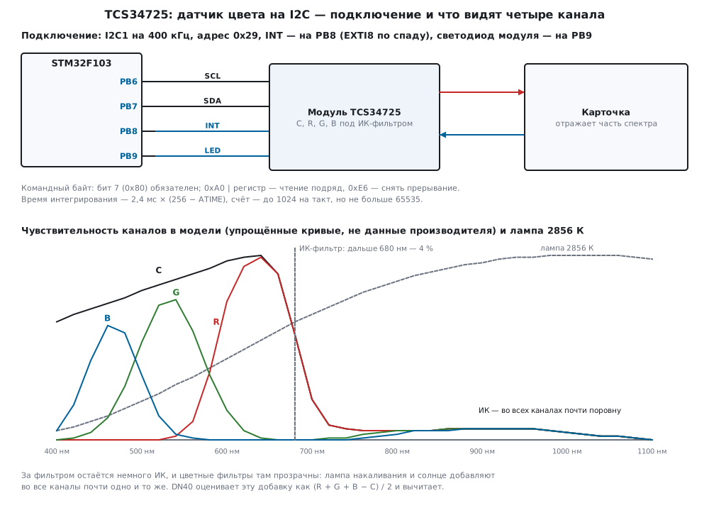
In section 103 the BH1750 measured illuminance as a single number, in 103а the MAX30102 shone into a finger and measured how much came back. The TCS34725 sees colour: it has four channels — behind red, green and blue filters and without a filter (Clear). From these four numbers you get the colour of an object, the illuminance and the colour temperature of the light. Here — what is inside and how to talk to it over I2C, how to choose integration time and gain, how to do white balance and recognise the colour of a card, how to compute lux and kelvins with the formulas of application note DN40 and why an incandescent lamp and the sun throw the sensor off, how the threshold interrupt works.
Sources: RM0008 (DocID13902 Rev 17): pin mode table, p. 160; AFIO_EXTICR3,
p. 191; EXTI_FTSR, p. 211; master reception of more than two bytes, method 2,
pp. 762–763; reception of a single byte, p. 764; I2C_CCR, pp. 783–784;
I2C_TRISE, p. 784. DocID13587 Rev 17 (STM32F103x8/xB): PB6 — I2C1_SCL, PB7 —
I2C1_SDA, both FT, p. 32; PB8 and PB9 — FT, p. 33. There is no TCS34725
document and no DN40 application note in the project: the address, the command
byte, registers, bits, the integration time formula, gain codes, persistence and
the DN40 formulas with coefficients are taken from the manufacturer's
documentation and built into the model — per the manufacturer's documentation,
not verified. The numbers in the command byte match the direct register numbers
of the related TCS3400 in the Zephyr 4.4.2 driver on disk, but that is a
different sensor and not a document. All numbers are a run of the driver
_verify/rgb103c/tcs103c.c and the processing col103c.c on a PC (gcc 12.2.0)
with our own model of the TCS34725 as an I2C slave, light sources and colour
cards in Python 3.11; the firmware was built with armclang 6.24 for Cortex-M3.
Sensitivity curves, spectra and cards in the model are simplified: the numbers
below describe the model, not the sensor.
What it is called in the documentation
Original Meaning RGBC (red, green, blue, clear) four channels: red, green, blue and without a colour filter IR blocking filter IR filter over the photodiodes command register, CMD bit the command byte, its bit 7 auto-increment / repeated byte the register number advances / does not advance integration time ( ATIME)integration time: how long light is accumulated analog gain ( AGAIN)gain AVALIDmeasurement finished, data fresh interrupt threshold ( AILT,AIHT)lower and upper Clear thresholds persistence ( APERS)how many measurements in a row beyond a threshold before an interrupt white balance white balance: a white card reads equal in all channels hue, saturation (HSV) hue and saturation correlated color temperature (CCT) colour temperature, K counts per lux (CPL) counts per lux device factor (DF), glass attenuation (GA) device factor and glass attenuation
103б.1 The sensor: four channels, the IR filter and the command byte
According to the manufacturer's documentation the TCS34725 contains a photodiode array: some under red, green and blue filters, some without a colour filter (Clear). Over everything is a filter that cuts near IR. Each channel has its own integrating ADC: light accumulates for a set time, the result is 16 bits. Modules add a regulator, pull-ups and a white illumination LED — it lights the object whose colour you want to know.
The bus address is 0x29 (byte on the line 0x52 for writing and 0x53 for reading, 17.2). The first byte of every write is the command byte. Bit 7 (0x80) is mandatory, bits 6:5 are the type: 00 — the register number does not advance, 01 — it advances after every byte, 11 — a special function; 0xE6 clears the Clear interrupt. Registers (per the manufacturer's documentation):
| Register | Number | In the command byte | What it holds |
|---|---|---|---|
ENABLE |
0x00 | 0x80 | AIEN [4], WEN [3], AEN [1], PON [0] |
ATIME |
0x01 | 0x81 | integration time |
WTIME |
0x03 | 0x83 | pause between measurements |
AILTL…AIHTH |
0x04…0x07 | 0x84…0x87 | Clear thresholds, low byte first |
PERS |
0x0C | 0x8C | APERS [3:0] |
CONFIG |
0x0D | 0x8D | WLONG [1]: pause × 12 |
CONTROL |
0x0F | 0x8F | AGAIN [1:0]: 1×, 4×, 16×, 60× |
ID |
0x12 | 0x92 | 0x44 — TCS34721 and TCS34725, 0x4D — TCS34723 and TCS34727 |
STATUS |
0x13 | 0x93 | AINT [4], AVALID [0] |
CDATAL…BDATAH |
0x14…0x1B | 0x94…0x9B | C, R, G, B two bytes each, low byte first |
Cross-check with Zephyr 4.4.2. There is no ready TCS34725 driver there, but there
is the related TCS3400. Its register numbers are written directly, without a
command bit, and match the "In the command byte" column: ENABLE 0x80 with PON,
AEN and AIEN in bits 0, 1 and 4, ATIME 0x81, PERS 0x8C, CONTROL 0x8F,
ID 0x92, STATUS 0x93 with AVALID in bit 0, CDATAL…BDATAH 0x94…0x9B in the
order C, R, G, B, low byte first. Time is set the same way: you write 256 minus
the number of cycles. The INT pin in the binding is open drain, active low. The
TCS3400 clears its interrupt differently (register 0xE7), and its ID is 0x90 or
0x93.
What the model makes of this: a command byte without bit 7 is not understood by the model, the transfer changes nothing, and reading continues from the previous number — this is a model assumption, the document was not checked here.
103б.2 Connecting to the F103 and initialisation
| Module pin | STM32F103 | Purpose |
|---|---|---|
| VIN | 3.3 V | module supply |
| GND | GND | ground |
| SCL | PB6 | I2C1 clock |
| SDA | PB7 | I2C1 data |
| INT | PB8 | threshold interrupt, active low, open drain |
| LED | PB9 | illumination LED: one — lit (as on common modules) |
I2C1 — as in 15б.2: 400 kHz, CCR = F/S | 30, TRISE = 11. PB8 is an input
with pull-up, EXTI8 on the falling edge: in AFIO_EXTICR3 (p. 191) code 0001 —
port B, EXTI_FTSR (p. 211) — falling edge, as in 103а.3. PB9 is a push-pull
output at 2 MHz (CNF = 00, MODE = 10; RM0008, p. 160). PB6…PB9 are FT
(pp. 32–33): on modules powered from 5 V the pull-ups are sometimes to 5 V —
check the schematic of your module (not verified).
Initialisation — check the ID, turn on the oscillator (PON), wait 2.4 ms, set
time, gain, persistence and thresholds, clear the interrupt and only then enable
measurements (AEN):
/* проверить ID, включить генератор, выждать 2,4 мс, настроить, запустить измерения */
int tcs_init(tcs_t *d, const tcs_cfg_t *c)
{
    int rc;
    d->xfers = d->errors = 0;
    if ((rc = tcs_get(d, TCS_ID, &d->id)) != TCS_OK)
        return rc;
    if (d->id != TCS_ID_25 && d->id != TCS_ID_27)
        return TCS_E_ID;                                /* по адресу 0x29 не TCS3472x */
    if ((rc = tcs_reg(d, TCS_ENABLE, TCS_EN_PON)) != TCS_OK)
        return rc;
    tcs_port_delay_us(TCS_PON_US);
    if ((rc = tcs_reg(d, TCS_ATIME, c->atime)) != TCS_OK || (rc = tcs_reg(d, TCS_CONTROL, c->again & 3u)) != TCS_OK
        || (rc = tcs_reg(d, TCS_PERS, c->pers & 0x0Fu)) != TCS_OK || (rc = tcs_thresholds(d, c->lo, c->hi)) != TCS_OK
        || (rc = tcs_clear_int(d)) != TCS_OK)
        return rc;
    d->atime = c->atime;
    d->again = c->again & 3u;
    d->enable = (uint8_t)(TCS_EN_PON | TCS_EN_AEN | (c->aien ? TCS_EN_AIEN : 0u));
    return tcs_reg(d, TCS_ENABLE, d->enable);
}
In the model tcs_init is 8 transfers: reading ID (92), 80 01 (PON),
81 C0, 8F 02, 8C 00, thresholds in one transfer A4 00 00 FF FF, E6 and
80 03 (PON + AEN). 650 µs on the bus, together with the pause after PON —
3050 µs. ID 0x4D is accepted too, a foreign one (0x11) is refused with TCS_E_ID,
−3. After power-up the model has ATIME = 0xFF, CONTROL = 0.
Data are read in one transfer starting at STATUS: command byte 0xB3 (0x80 |
0x20 | 0x13), then 9 bytes — status and C, R, G, B. One register number for
everything, and the low byte of each channel first:
/* STATUS и восемь байт C, R, G, B одним чтением: командный байт 0xB3, номер растёт */
int tcs_read(tcs_t *d, tcs_rgbc_t *v)
{
    uint8_t c = (uint8_t)(TCS_CMD | TCS_AUTO | TCS_STATUS), b[9];
    int rc = xfer_done(d, tcs_port_xfer(d->addr, &c, 1, b, 9));
    if (rc != TCS_OK)
        return rc;
    d->status = b[0];
    v->c = (uint16_t)(b[1] | b[2] << 8);                /* младший байт первым */
    v->r = (uint16_t)(b[3] | b[4] << 8);
    v->g = (uint16_t)(b[5] | b[6] << 8);
    v->b = (uint16_t)(b[7] | b[8] << 8);
    return TCS_OK;
}
That is 111 SCL clocks, 277.5 µs at 400 kHz. A measurement "on request" is
tcs_measure: clear and set AEN again (a new start clears AVALID), wait the
integration time and 2.4 ms of preparation, read. In the model with ATIME 0xC0
it takes 3 transfers, 422.5 µs of bus and 156.4 ms in total.
103б.3 Integration time, gain and auto-ranging
Integration time is 2.4 ms × (256 − ATIME). The count grows by 1024 per cycle,
but the register is 16-bit, so the full scale is 1024 × (256 − ATIME), but not
more than 65535. In the model, channel C under very bright light at 1×:
ATIME |
Cycles | Time | Full scale in the model | Measurement | Object (2 measurements) |
|---|---|---|---|---|---|
| 0xFF | 1 | 2.4 ms | 1024 | 5.2 ms | 10.4 ms |
| 0xF6 | 10 | 24 ms | 10 240 | 26.8 ms | 53.6 ms |
| 0xEB | 21 | 50.4 ms | 21 504 | 53.2 ms | 106.4 ms |
| 0xE7 | 25 | 60 ms | 25 600 | 62.8 ms | 125.6 ms |
| 0xD5 | 43 | 103.2 ms | 44 032 | 106 ms | 212 ms |
| 0xC0 | 64 | 153.6 ms | 65 535 | 156.4 ms | 312.8 ms |
| 0x00 | 256 | 614.4 ms | 65 535 | 617.2 ms | 1234.4 ms |
From 64 cycles on the scale no longer grows: accumulating longer is only slower (103б.7). The driver detects saturation by the full scale:
/* 1024 на такт, но не больше 16 бит */
uint32_t tcs_max_count(uint8_t atime)
{
    uint32_t m = 1024u * tcs_cycles(atime);
    return m > 65535u ? 65535u : m;
}
Gain is 1×, 4×, 16×, 60× (per the manufacturer's documentation; the actual
factors vary between parts, not verified). In the model, 100 lx of light, ATIME
0xC0, 20 measurements:
| Code | Gain | Clear, mean | Ratio to 1× | Spread |
|---|---|---|---|---|
| 0 | 1× | 119.9 | 1.00 | 1.37 % |
| 1 | 4× | 471 | 3.93 | 1.23 % |
| 2 | 16× | 1876.3 | 15.65 | 1.20 % |
| 3 | 60× | 7028.6 | 58.62 | 1.20 % |
The ratios are not exactly 4, 16 and 60 because of the dark count: in the model Clear has 3 units at any gain. The spread hardly depends on gain: noise in the model comes from the number of caught photons, and gain multiplies it too.
Flicker. Mains lamps blink at 100 Hz. A short integration time catches now a peak, now a dip. In the model an LED lamp of 300 lx flickers by 30 %, 60×, 40 measurements at random moments:
ATIME |
Time | 100 Hz periods | Clear spread | Without flicker |
|---|---|---|---|---|
| 0xFF | 2.4 ms | 0.24 | 67.44 % | 25.15 % |
| 0xF6 | 24 ms | 2.4 | 15.32 % | 8.47 % |
| 0xEB | 50.4 ms | 5.04 | 6.09 % | 5.85 % |
| 0xE7 | 60 ms | 6 | 5.36 % | 5.36 % |
| 0xD5 | 103.2 ms | 10.32 | 5.32 % | 4.09 % |
At 60 ms there are exactly 6 periods, and flicker cancels out completely: the spread is the same as without it. With 50 Hz mains you take a time that is a multiple of 10 ms: 2.4 ms × 25 = 60 ms.
Auto-ranging. Seven steps — from 1 cycle at 1× to 256 cycles at 60× (sensitivity 1, 10, 64, 256, 1024, 3840, 15360). Hit the full scale — one step down; otherwise — the most sensitive step where Clear is expected below 70 % of the scale:
/* автоподбор: упёрлись в шкалу — ступенью ниже; иначе самая чувствительная ступень, где Clear ожидается
 * ниже 70 % шкалы; совпала с текущей — готово */
int col_auto(tcs_t *d, uint32_t *step, tcs_rgbc_t *v, uint32_t *tries)
{
    uint32_t k = *step < COL_STEPS ? *step : 0u;
    int rc;
    for (*tries = 1;; (*tries)++) {
        if ((rc = tcs_set(d, col_steps[k].atime, col_steps[k].again)) != TCS_OK || (rc = tcs_measure(d, v)) != TCS_OK)
            return rc;
        uint32_t j = k;
        if (col_saturated(v, col_steps[k].atime)) {
            if (k == 0u)
                break;                                  /* ярче шкалы даже на самой грубой ступени */
            j = k - 1u;
        } else {
            for (j = COL_STEPS - 1u; j > 0u; j--) {
                uint64_t want = (uint64_t)v->c * sens(j) / sens(k);
                if (want * 100u < (uint64_t)tcs_max_count(col_steps[j].atime) * COL_FILL_PCT)
                    break;
            }
        }
        if (j == k || *tries >= COL_AUTO_TRIES)
            break;
        k = j;
    }
    *step = k;
    return TCS_OK;
}
In the model, starting from step 2 (64 cycles, 1×; steps are counted from zero):
| Light | Step | Tries | ATIME, gain |
Clear | Fill | Time | Lux by DN40 |
|---|---|---|---|---|---|---|---|
| lamp, 1 lx | 6 | 2 | 0x00, 60× | 294 | 0.4 % | 774.2 ms | 0.7 |
| lamp, 10 lx | 6 | 2 | 0x00, 60× | 2897 | 4.4 % | 774.2 ms | 7.9 |
| lamp, 300 lx | 5 | 2 | 0xC0, 60× | 21 676 | 33.1 % | 313.4 ms | 239.2 |
| lamp, 3000 lx | 3 | 2 | 0xC0, 4× | 14 443 | 22 % | 313.4 ms | 2395.8 |
| sun, 30 000 lx | 0 | 2 | 0xFF, 1× | 733 | 71.6 % | 162.2 ms | 25 666.4 |
| sun, 100 000 lx | 0 | 3 | 0xFF, 1× | 1024 | 100 % | 189.3 ms | saturated |
The lamp here is an LED lamp, the sun is a 5800 K black body. At 100 000 lx even the coarsest step is not enough: 1024 in 2.4 ms. In the model the Clear channel saturates at 1× and 2.4 ms somewhere between 30 000 and 100 000 lx; outdoors the sensor is put behind attenuating glass — that is what the GA factor in DN40 accounts for (103б.5). At 1 lx Clear is 294 counts, and lux by DN40 is 0.7: the dark count and noise are already noticeable here.
103б.4 White balance and the colour of an object
The colour of an object is how it reflects the illumination light. Room light is reflected too and also reaches the channels, and it changes. So the object reading is the difference of two measurements: with the LED and without it. Between them the driver restarts the measurement so that none of them is half with light and half without:
/* отсчёт предмета: со светодиодом минус без него — внешний свет вычитается */
int col_object(tcs_t *d, col_v_t *o, int *sat)
{
    tcs_rgbc_t on, off;
    int rc;
    tcs_port_led(1);
    rc = tcs_measure(d, &on);
    tcs_port_led(0);
    if (rc != TCS_OK || (rc = tcs_measure(d, &off)) != TCS_OK)
        return rc;
    *sat = col_saturated(&on, d->atime);
    o->c = (int32_t)on.c - off.c;
    o->r = (int32_t)on.r - off.r;
    o->g = (int32_t)on.g - off.g;
    o->b = (int32_t)on.b - off.b;
    return TCS_OK;
}
White balance. The channels differ in sensitivity, and the white light of the LED is not flat: the raw reading of a white card in the model is C 14 938, R 4337, G 5510, B 3619. So two reference readings are taken: a black card (dark — what remains without an object: stray light inside the module and noise) and a white one. After that each channel is the fraction of the way from dark to white, in thousandths:
/* баланс белого: (x − тёмный) / (белый − тёмный), белая карточка — 1000 в каждом канале */
void col_balance(const col_wb_t *wb, const col_v_t *o, int32_t out[3])
{
    const int32_t x[3] = {o->r, o->g, o->b}, dk[3] = {wb->dark.r, wb->dark.g, wb->dark.b},
                  wh[3] = {wb->white.r, wb->white.g, wb->white.b};
    for (int i = 0; i < 3; i++) {
        int32_t span = wh[i] - dk[i];
        out[i] = span > 0 ? (int32_t)((int64_t)(x[i] - dk[i]) * 1000 / span) : 0;
    }
}
The white card after balance is 996, 1001 and 991 (this is a repeated
measurement, not the same figure). The step for objects is chosen on the white
card with the LED: in the model at 10 mm it is ATIME 0xC0 and 16×, Clear 15 708
— a quarter of the scale, so that bright objects do not hit it.
Chromaticity and hue. From the balance you get the fractions r, g, b (sum — 1000): they do not depend on brightness. HSV hue is an angle on the colour wheel: 0° — red, 120° — green, 240° — blue. In the model, 12 cards at 10 mm:
| Card | R, G, B after balance | r, g, b | Hue | Saturation |
|---|---|---|---|---|
| white | 991, 999, 994 | 332, 334, 333 | — | 0.008 |
| grey | 314, 307, 314 | 335, 328, 335 | — | 0.022 |
| black | −2, −3, 4 | 0, 0, 1000 | — | 1 |
| red | 544, 58, 17 | 878, 93, 27 | 4.6° | 0.968 |
| orange | 790, 177, 24 | 797, 178, 24 | 11.9° | 0.969 |
| yellow | 947, 695, 103 | 542, 398, 59 | 42° | 0.891 |
| green | 114, 424, 178 | 159, 592, 248 | 132.3° | 0.731 |
| cyan | 147, 613, 766 | 96, 401, 501 | 194.9° | 0.808 |
| blue | 14, 84, 435 | 26, 157, 816 | 230.1° | 0.967 |
| violet | 219, 52, 247 | 422, 100, 476 | 291.3° | 0.789 |
| pink | 821, 487, 437 | 470, 279, 250 | 7.8° | 0.467 |
| brown | 227, 52, 19 | 761, 174, 63 | 9.5° | 0.916 |
White, grey and black have no hue: the first two have saturation near 0, black has all channels near zero, and the angle is noise. Red, pink and brown are almost the same by hue (4.6°, 7.8° and 9.5°): brightness and saturation tell them apart. So recognition is done not by one angle but by the nearest reference — a card captured beforehand. The distance is the sum of squared differences:
/* ближайший эталон по сумме квадратов разностей */
uint32_t col_nearest(const int32_t (*ref)[3], uint32_t n, const int32_t x[3])
{
    uint32_t best = 0;
    int64_t bd = -1;
    for (uint32_t i = 0; i < n; i++) {
        int64_t s = 0;
        for (int k = 0; k < 3; k++) {
            int64_t e = (int64_t)x[k] - ref[i][k];
            s += e * e;
        }
        if (bd < 0 || s < bd) {
            bd = s;
            best = i;
        }
    }
    return best;
}
Accuracy in the model. 240 random cards at 10 ± 0.5 mm, references captured under an LED lamp of 300 lx. Two ways of comparing: by R, G, B after balance (reflectance) and by the fractions r, g, b (chromaticity):
| Light during measurement | With LED minus without, reflectance / chromaticity | LED reading only, reflectance / chromaticity |
|---|---|---|
| lamp, 300 lx | 100 / 90 % | 100 / 90.4 % |
| dark | 100 / 89.2 % | 99.6 / 90 % |
| incandescent lamp, 500 lx | 100 / 88.8 % | 92.9 / 75.4 % |
| sun, 20 000 lx | 100 / 82.9 % (saturated in 20) | 8.3 / 54.6 % (saturated in 20) |
Subtracting the reading without the LED makes recognition almost independent of room light. Without it the references are valid only under the light in which they were captured. Chromaticity loses about 10 %: white, grey and black are the same for it. Under the sun 20 readings out of 240 hit the scale, and the processing set the saturation flag: they cannot be trusted, even if guessed right.
103б.5 Colour temperature, illuminance and IR
For illuminance and colour temperature the sensor looks at the light, not at an object, and the LED is off. The formulas are from the manufacturer's application note DN40 (per the application note, not verified):
IR = (R + G + B − C) / 2; R′ = R − IR, G′ = G − IR, B′ = B − IR
lux = (0.136 · R′ + 1.000 · G′ − 0.444 · B′) / CPL, CPL = (2.4 ms × cycles) × gain / (GA × DF)
CCT = 3810 · B′ / R′ + 1391
Here DF = 310 is the device factor, GA is the glass attenuation (1 without glass). All six numbers are parameters: the manufacturer obtained them for its own curves and its own package; for your glass and module they are measured anew. In the code they live in one structure, lux is computed in tenths with integers:
/* DN40: IR = (R + G + B − C) / 2; X' = X − IR; люксы = (r·R' + g·G' + b·B') / CPL,
 * CPL = (2,4 мс × такты) × усиление / (GA × DF); CCT = ct_coef × B'/R' + ct_off */
void col_light(const tcs_rgbc_t *v, uint8_t atime, uint8_t again, const col_dn40_t *p, col_light_t *out)
{
    int32_t ir = p->ir_sub ? ((int32_t)v->r + v->g + v->b - v->c) / 2 : 0;
    if (ir < 0)
        ir = 0;
    int32_t r = v->r - ir, g = v->g - ir, b = v->b - ir;
    int64_t s = (int64_t)p->r * r + (int64_t)p->g * g + (int64_t)p->b * b;
    int64_t den = (int64_t)240000 * tcs_cycles(atime) * tcs_gain_x(again);
    out->ir = ir;
    out->lux10 = (int32_t)(s * p->ga * p->df / den);
    out->cct = r > 0 ? (int32_t)((int64_t)p->ct_coef * b / r + p->ct_off) : 0;
    out->sat = col_saturated(v, atime);
}
Why IR. Colour filters are transparent in the near IR, the IR filter lets a little through — and whatever passes adds to all channels almost equally. An LED lamp has almost no IR, an incandescent lamp and the sun have a lot. An equal addition washes out colour and inflates lux. The DN40 estimate (R + G + B − C) / 2 relies on R + G + B ≈ C in the visible part, while in the IR each channel sees the same as Clear. In the model, 500 lx, no calibration except the scale on the 2856 K lamp:
| Light | IR in Clear, actual | DN40 estimate | Lux | Lux without IR removal | CCT by DN40 | CCT, actual |
|---|---|---|---|---|---|---|
| incandescent lamp, 2856 K | 17.4 % | 10.5 % | 496.9 | 630.1 | 2007 | 2856 |
| black body 2700 K | 19.8 % | 12.9 % | 503.4 | 674.1 | 1918 | 2700 |
| black body 4000 K | 8.5 % | 1.2 % | 476.3 | 489 | 2711 | 4000 |
| black body 5000 K | 5.7 % | 0 % | 445.4 | 445.4 | 3179 | 5000 |
| black body 6500 K | 3.8 % | 0 % | 411.6 | 411.6 | 3798 | 6500 |
| sun (black body 5800 K) | 4.5 % | 0 % | 424.8 | 424.8 | 3517 | 5800 |
| LED lamp, warm | 0.5 % | 0 % | 393.2 | 393.2 | 2025 | — |
| LED lamp, cool | 0.1 % | 0 % | 343.8 | 343.8 | 4520 | — |
Under an incandescent lamp without IR removal lux is inflated by a quarter (630.1 instead of 500), with removal — 496.9. But the estimate is rough: in the model it finds less IR than there is, and zero for cool sources, because in the visible part R + G + B of the model is not equal to C. Colour temperature with the application-note coefficients is understated in the model by a factor of 1.4–1.7: the model curves are not the sensor curves. That is the lesson: DN40 coefficients are a starting point, not the truth.
Calibration. Colour temperature is easiest to correct with two known lamps. In the model B′/R′ at 2856 K is 0.1619, at 6500 K — 0.6318, giving a coefficient of 7755 and an offset of 1600:
| Light | 2856 K | 2700 K | 4000 K | 5000 K | 6500 K | 5800 K |
|---|---|---|---|---|---|---|
| CCT after calibration | 2855 | 2674 | 4288 | 5239 | 6499 | 5928 |
For lux the three coefficients are fitted by least squares over several lamps with a lux meter. In the model, over all eight sources, this gave 0.272 with a minus sign, 2.417 and 1.572 with a minus sign, and all eight readings fell within 479.1…538.8 lx with 500 actual (it was 343.8…503.4).
103б.6 Clear threshold interrupt and persistence
The sensor itself compares Clear with two thresholds at the end of each
measurement. Going beyond the thresholds the required number of times in a row
sets AINT, and with AIEN the INT pin goes low until the interrupt is cleared
with command 0xE6. The number of times is set by APERS (per the manufacturer's
documentation): 0 — every measurement, regardless of thresholds; 1, 2, 3 — the
same number; beyond that in steps of 5: code 4 — 5, code 5 — 10, …, code 15 —
60. Thresholds are written in one transfer:
/* пороги Clear одним обменом: 0x04…0x07 подряд, номер растёт (TYPE = 01) */
int tcs_thresholds(tcs_t *d, uint16_t lo, uint16_t hi)
{
    uint8_t b[5] = {(uint8_t)(TCS_CMD | TCS_AUTO | TCS_AILTL), (uint8_t)lo, (uint8_t)(lo >> 8), (uint8_t)hi, (uint8_t)(hi >> 8)};
    return xfer_done(d, tcs_port_xfer(d->addr, b, 5, 0, 0));
}
/* снять AINT: один командный байт специальной функции, без данных */
int tcs_clear_int(tcs_t *d)
{
    uint8_t c = TCS_SF_CLEAR;
    return xfer_done(d, tcs_port_xfer(d->addr, &c, 1, 0, 0));
}
This is how the firmware waits for the light to change without polling the sensor. In the model an LED lamp of 300 lx with 30 % flicker, 60×, thresholds ±20 % of the mean, after 3 s the light drops to 30 lx. False interrupts — over the first 3 s:
APERS |
In a row | 2.4 ms: false | 2.4 ms: delay | 60 ms: false | 60 ms: delay |
|---|---|---|---|---|---|
| 1 | 1 | 517 | 0.7 ms | 0 | 65.5 ms |
| 2 | 2 | 54 | 0.7 ms | 0 | 125.5 ms |
| 3 | 3 | 15 | 3.1 ms | 0 | 185.5 ms |
| 4 | 5 | 1 | 7.9 ms | 0 | 305.5 ms |
| 5 | 10 | 0 | 19.9 ms | 0 | 605.5 ms |
At 2.4 ms the sensor sees every flicker dip, and the ±20 % threshold is crossed
hundreds of times. Persistence cuts them off at the cost of delay. At 60 ms the
flicker cancels by itself (103б.3), there are none even with APERS = 1, and the
delay is one measurement. Choose the time first — a multiple of 10 ms, then
APERS. The "watchdog" mode in the firmware is built this way: 60 ms, 16×,
thresholds ±25 % of the current Clear, APERS = 4.
103б.7 Pitfalls
Zeros are read. The command bit is forgotten: register number 0x14 is written as is. In the model such a byte is not understood, and eight bytes came from the previous number — 00 00 00 00 00 00 00 00 instead of C, R, G, B (how the chip behaves was not verified).
All channels are the same. Command byte 0x94 without type 01: the register
number does not advance, and CDATAL is read eight times. In the model —
B3 B3 B3 B3 B3 B3 B3 B3 with Clear 5811 (0x16B3). For sequential reading —
0xA0 | number.
The module LED leaks into the reading. Lux and colour temperature are measured with the LED off. In the model an LED shining straight onto the photodiodes, under a warm lamp of 100 lx, raises the readings from 78.4 to 106.2 lx and from 2891 to 3777 K (coefficients — after calibration in 103б.5). The LED pin of the module goes to an MCU pin, not to the supply.
In bright light everything is white. The channels hit the scale: Clear tops
out first, then the others, and the fractions get skewed. Check col_saturated
and do not trust a saturated reading; in the sun even 2.4 ms at 1× is too much
(103б.3).
The wrong colour is recognised once the card is moved. The LED light on the object falls as the square of distance. In the model the references were captured at 10 mm:
| Distance | 5 mm | 8 mm | 10 mm | 15 mm | 20 mm | 30 mm |
|---|---|---|---|---|---|---|
| by reflectance | 8.3 % | 74.2 % | 100 % | 8.8 % | 8.8 % | 8.8 % |
| by chromaticity | 72.1 % | 82.9 % | 90 % | 62.9 % | 63.3 % | 30.8 % |
Closer — everything is brighter than the white reference and 6 readings saturate, further — everything is darker than the black one; chromaticity holds longer, but stray light inside the module and noise eat it too. Distance is fixed: a tube, a stop, a holder. Angle is a related problem: a glossy card at a right angle reflects the LED like a mirror. In the model 8 % glare lowers the saturation of the red card from 0.969 to 0.828 and accuracy to 88.8 / 62.9 %. The sensor is held at an angle to a glossy surface, or a matte one is used.
Module from 5 V. The chip itself, per the manufacturer's documentation, runs from 3.3 V; modules with a regulator also accept 5 V, but the SDA, SCL and INT pull-ups may end up at 5 V. PB6…PB9 are FT (pp. 32–33), an ordinary pin does not tolerate this. A module without a regulator from 5 V will burn out (not verified).
Slow: one reading per second. ATIME = 0x00 is 614.4 ms, and an object is
two measurements: 1234.4 ms in the model. The scale stops growing from 64 cycles
(103б.3): there is no point in going beyond 153.6 ms, except in near darkness.
An interrupt on every measurement. APERS = 0 sets AINT always, thresholds
do not matter: in the model after tcs_init with zero STATUS = 0x11. For the
watchdog mode — APERS from 1.
103б.8 Summary
- TCS34725 — C, R, G, B channels under an IR filter, 16 bits, I2C, address 0x29; the first byte is a command byte with bit 0x80, 0xA0 | number — sequential read, 0xE6 — clear the interrupt; all of this per the manufacturer's documentation.
- Integration time is 2.4 ms × (256 −
ATIME), full scale is 1024 × (256 −ATIME), but not more than 65535; from 64 cycles (153.6 ms) it no longer grows. Gain is 1×, 4×, 16×, 60×. - A time that is a multiple of 10 ms (60 ms — 25 cycles) cancels 100 Hz flicker: in the model the spread is 5.36 % versus 67.44 % at 2.4 ms.
- Object colour — with the LED minus without it, balance on black and white cards, nearest reference: in the model 100 % at 10 mm under any light, except saturation; distance must be fixed.
- Lux and colour temperature — DN40 with IR removal; coefficients are parameters: in the model CCT by the application note is understated by a factor of 1.4–1.7, after calibration on 2856 and 6500 K — 2674…6499 K for black bodies.
- Incandescent IR without removal inflates lux by a quarter (630.1 instead of 500 in the model).
- Clear threshold interrupt — with persistence: at 2.4 ms and
APERS1 — 517 false ones in 3 s, at 60 ms — none.
Full sources
tcs103c.h — registers, bits, port and functions of the TCS34725 driver.
/* tcs103c.h — раздел 103б: драйвер датчика цвета TCS34725 (фотодиоды R, G, B и Clear под ИК-фильтром) по I2C
 * без регистров микроконтроллера. Драйвер говорит с микросхемой только через функции порта (tcs_port_*):
 * в прошивке fw103c.c их делает I2C1 STM32F103, в стенде host103c.c — модель model103c.py.
 * Адрес, командный байт, карта регистров и биты — по документации производителя; документа в проекте нет,
 * с микросхемой не сверено. Номера в командном байте (0x80 | регистр) совпадают с прямыми номерами регистров
 * родственного TCS3400 в драйвере Zephyr 4.4.2. */
#ifndef TCS103C_H
#define TCS103C_H
#include <stdint.h>

/* ── командный байт: первый байт каждой записи ────────────────────────── */
#define TCS_CMD           0x80u         /* бит 7: это команда — без него байт не понят */
#define TCS_AUTO          0x20u         /* TYPE = 01: номер регистра растёт после каждого байта */
#define TCS_SF_CLEAR      0xE6u         /* TYPE = 11, функция 00110: снять прерывание по Clear */

/* ── регистры ─────────────────────────────────────────────────────────── */
#define TCS_ENABLE        0x00u         /* AIEN [4], WEN [3], AEN [1], PON [0] */
#define TCS_ATIME         0x01u         /* время интегрирования: 2,4 мс × (256 − ATIME) */
#define TCS_WTIME         0x03u         /* пауза между измерениями: 2,4 мс × (256 − WTIME) */
#define TCS_AILTL         0x04u         /* 0x04…0x07 — нижний и верхний пороги Clear, младший байт первым */
#define TCS_PERS          0x0Cu         /* APERS [3:0]: сколько измерений подряд за порогом */
#define TCS_CONFIG        0x0Du         /* WLONG [1]: пауза × 12 */
#define TCS_CONTROL       0x0Fu         /* AGAIN [1:0]: 1×, 4×, 16×, 60× */
#define TCS_ID            0x12u
#define TCS_STATUS        0x13u         /* AINT [4], AVALID [0] */
#define TCS_CDATAL        0x14u         /* 0x14…0x1B — C, R, G, B по два байта, младший первым */

/* ── биты ─────────────────────────────────────────────────────────────── */
#define TCS_EN_PON        0x01u         /* генератор включён */
#define TCS_EN_AEN        0x02u         /* измерения идут */
#define TCS_EN_WEN        0x08u         /* пауза WTIME между измерениями */
#define TCS_EN_AIEN       0x10u         /* прерывание по порогу Clear выводит INT в ноль */
#define TCS_ST_AVALID     0x01u         /* измерение закончено */
#define TCS_ST_AINT       0x10u         /* Clear вышел за пороги */

#define TCS_ADDR          0x29u         /* семибитный: 0x52 запись, 0x53 чтение */
#define TCS_ID_25         0x44u         /* TCS34721 и TCS34725 */
#define TCS_ID_27         0x4Du         /* TCS34723 и TCS34727 */
#define TCS_CYCLE_US      2400u         /* один такт интегрирования */
#define TCS_PON_US        2400u         /* после PON — не меньше 2,4 мс до AEN */
#define TCS_WAIT_TRIES    8u

enum { TCS_OK = 0, TCS_E_NACK = -1, TCS_E_BUS = -2, TCS_E_ID = -3, TCS_E_TIMEOUT = -4 };
enum { TCS_GAIN_1 = 0, TCS_GAIN_4 = 1, TCS_GAIN_16 = 2, TCS_GAIN_60 = 3 };

typedef struct {
    uint8_t atime;                      /* 0xFF — 1 такт, 2,4 мс; 0x00 — 256 тактов */
    uint8_t again;                      /* TCS_GAIN_* */
    uint8_t pers;                       /* APERS, 0…15 */
    uint16_t lo, hi;                    /* пороги Clear */
    uint8_t aien;                       /* 1 — прерывание по порогу */
} tcs_cfg_t;

typedef struct {
    uint8_t addr;
    uint8_t id, status, enable;
    uint8_t atime, again;               /* то, что сейчас записано в микросхему */
    uint32_t xfers, errors;
} tcs_t;

typedef struct {
    uint16_t c, r, g, b;
} tcs_rgbc_t;

/* ── порт: в прошивке — I2C1 и вывод светодиода, в стенде — строки к модели ── */
/* ntx байт записи, затем (если nrx) повторный старт и nrx байт чтения; 0, TCS_E_NACK или TCS_E_BUS */
int tcs_port_xfer(uint8_t addr7, const uint8_t *tx, uint32_t ntx, uint8_t *rx, uint32_t nrx);
void tcs_port_delay_us(uint32_t us);
void tcs_port_led(int on);              /* светодиод подсветки модуля */

/* ── драйвер ──────────────────────────────────────────────────────────── */
int tcs_reg(tcs_t *d, uint8_t reg, uint8_t v);
int tcs_get(tcs_t *d, uint8_t reg, uint8_t *v);
int tcs_init(tcs_t *d, const tcs_cfg_t *c);
int tcs_set(tcs_t *d, uint8_t atime, uint8_t again);
int tcs_thresholds(tcs_t *d, uint16_t lo, uint16_t hi);
int tcs_clear_int(tcs_t *d);
int tcs_read(tcs_t *d, tcs_rgbc_t *v);
int tcs_measure(tcs_t *d, tcs_rgbc_t *v);
uint32_t tcs_cycles(uint8_t atime);
uint32_t tcs_atime_us(uint8_t atime);
uint32_t tcs_max_count(uint8_t atime);
uint32_t tcs_gain_x(uint8_t again);

#endif
tcs103c.c — driver: command byte, initialisation, thresholds, reading and measurement.
/* tcs103c.c — раздел 103б: драйвер TCS34725 по I2C. Один и тот же файл собирается в прошивку (armclang,
 * Cortex-M3) и в стенд на компьютере (gcc): микроконтроллера он не знает, только порт tcs_port_*. */
#include "tcs103c.h"

static int xfer_done(tcs_t *d, int rc)
{
    d->xfers++;
    if (rc)
        d->errors++;
    return rc;
}

/* запись одного регистра: командный байт 0x80 | номер, затем значение */
int tcs_reg(tcs_t *d, uint8_t reg, uint8_t v)
{
    uint8_t b[2] = {(uint8_t)(TCS_CMD | reg), v};
    return xfer_done(d, tcs_port_xfer(d->addr, b, 2, 0, 0));
}

int tcs_get(tcs_t *d, uint8_t reg, uint8_t *v)
{
    uint8_t c = (uint8_t)(TCS_CMD | reg);
    return xfer_done(d, tcs_port_xfer(d->addr, &c, 1, v, 1));
}

uint32_t tcs_cycles(uint8_t atime)
{
    return 256u - atime;
}

uint32_t tcs_atime_us(uint8_t atime)
{
    return TCS_CYCLE_US * tcs_cycles(atime);
}

/* 1024 на такт, но не больше 16 бит */
uint32_t tcs_max_count(uint8_t atime)
{
    uint32_t m = 1024u * tcs_cycles(atime);
    return m > 65535u ? 65535u : m;
}

uint32_t tcs_gain_x(uint8_t again)
{
    static const uint8_t x[4] = {1, 4, 16, 60};
    return x[again & 3u];
}

/* пороги Clear одним обменом: 0x04…0x07 подряд, номер растёт (TYPE = 01) */
int tcs_thresholds(tcs_t *d, uint16_t lo, uint16_t hi)
{
    uint8_t b[5] = {(uint8_t)(TCS_CMD | TCS_AUTO | TCS_AILTL), (uint8_t)lo, (uint8_t)(lo >> 8), (uint8_t)hi, (uint8_t)(hi >> 8)};
    return xfer_done(d, tcs_port_xfer(d->addr, b, 5, 0, 0));
}

/* снять AINT: один командный байт специальной функции, без данных */
int tcs_clear_int(tcs_t *d)
{
    uint8_t c = TCS_SF_CLEAR;
    return xfer_done(d, tcs_port_xfer(d->addr, &c, 1, 0, 0));
}

/* проверить ID, включить генератор, выждать 2,4 мс, настроить, запустить измерения */
int tcs_init(tcs_t *d, const tcs_cfg_t *c)
{
    int rc;
    d->xfers = d->errors = 0;
    if ((rc = tcs_get(d, TCS_ID, &d->id)) != TCS_OK)
        return rc;
    if (d->id != TCS_ID_25 && d->id != TCS_ID_27)
        return TCS_E_ID;                                /* по адресу 0x29 не TCS3472x */
    if ((rc = tcs_reg(d, TCS_ENABLE, TCS_EN_PON)) != TCS_OK)
        return rc;
    tcs_port_delay_us(TCS_PON_US);
    if ((rc = tcs_reg(d, TCS_ATIME, c->atime)) != TCS_OK || (rc = tcs_reg(d, TCS_CONTROL, c->again & 3u)) != TCS_OK
        || (rc = tcs_reg(d, TCS_PERS, c->pers & 0x0Fu)) != TCS_OK || (rc = tcs_thresholds(d, c->lo, c->hi)) != TCS_OK
        || (rc = tcs_clear_int(d)) != TCS_OK)
        return rc;
    d->atime = c->atime;
    d->again = c->again & 3u;
    d->enable = (uint8_t)(TCS_EN_PON | TCS_EN_AEN | (c->aien ? TCS_EN_AIEN : 0u));
    return tcs_reg(d, TCS_ENABLE, d->enable);
}

/* новое время и усиление; измерение перезапускается, чтобы следующий отсчёт был целиком с новыми */
int tcs_set(tcs_t *d, uint8_t atime, uint8_t again)
{
    int rc;
    if ((rc = tcs_reg(d, TCS_ENABLE, (uint8_t)(d->enable & ~TCS_EN_AEN))) != TCS_OK)
        return rc;
    if ((rc = tcs_reg(d, TCS_ATIME, atime)) != TCS_OK || (rc = tcs_reg(d, TCS_CONTROL, again & 3u)) != TCS_OK)
        return rc;
    d->atime = atime;
    d->again = again & 3u;
    return tcs_reg(d, TCS_ENABLE, d->enable);
}

/* STATUS и восемь байт C, R, G, B одним чтением: командный байт 0xB3, номер растёт */
int tcs_read(tcs_t *d, tcs_rgbc_t *v)
{
    uint8_t c = (uint8_t)(TCS_CMD | TCS_AUTO | TCS_STATUS), b[9];
    int rc = xfer_done(d, tcs_port_xfer(d->addr, &c, 1, b, 9));
    if (rc != TCS_OK)
        return rc;
    d->status = b[0];
    v->c = (uint16_t)(b[1] | b[2] << 8);                /* младший байт первым */
    v->r = (uint16_t)(b[3] | b[4] << 8);
    v->g = (uint16_t)(b[5] | b[6] << 8);
    v->b = (uint16_t)(b[7] | b[8] << 8);
    return TCS_OK;
}

/* одно свежее измерение: перезапуск AEN (снимает AVALID), ожидание времени интегрирования, опрос AVALID */
int tcs_measure(tcs_t *d, tcs_rgbc_t *v)
{
    int rc;
    if ((rc = tcs_reg(d, TCS_ENABLE, (uint8_t)(d->enable & ~TCS_EN_AEN))) != TCS_OK
        || (rc = tcs_reg(d, TCS_ENABLE, d->enable)) != TCS_OK)
        return rc;
    tcs_port_delay_us(tcs_atime_us(d->atime) + TCS_CYCLE_US);
    for (uint32_t i = 0; i < TCS_WAIT_TRIES; i++) {
        if ((rc = tcs_read(d, v)) != TCS_OK)
            return rc;
        if (d->status & TCS_ST_AVALID)
            return TCS_OK;
        tcs_port_delay_us(TCS_CYCLE_US);
    }
    return TCS_E_TIMEOUT;
}
col103c.h — processing parameters and DN40 coefficients.
/* col103c.h — раздел 103б: обработка отсчётов TCS34725 целыми числами (у F103 нет FPU): автоподбор времени и
 * усиления, отсчёт предмета без внешнего света, баланс белого, цветность, оттенок, ближайший эталон,
 * освещённость и цветовая температура по формулам аппнотки DN40 (коэффициенты — параметры, не проверено). */
#ifndef COL103C_H
#define COL103C_H
#include <stdint.h>
#include "tcs103c.h"

#define COL_STEPS      7u               /* ступени автоподбора: от самой грубой к самой чувствительной */
#define COL_FILL_PCT   70u              /* ступень годится, если Clear на ней ожидается ниже 70 % шкалы */
#define COL_AUTO_TRIES 8u

typedef struct {
    uint8_t atime, again;
} col_step_t;

extern const col_step_t col_steps[COL_STEPS];

typedef struct {
    int32_t c, r, g, b;                 /* со знаком: разность двух отсчётов может уйти ниже нуля */
} col_v_t;

typedef struct {
    col_v_t dark, white;                /* тёмный отсчёт и белая карточка */
} col_wb_t;

/* коэффициенты DN40: r, g, b — ×1000; df — множитель устройства; ga — ослабление стекла ×1000 */
typedef struct {
    int32_t r, g, b;
    int32_t ct_coef, ct_off;
    int32_t df, ga;
    int ir_sub;                         /* 1 — вычитать ИК-оценку (R + G + B − C) / 2 */
} col_dn40_t;

extern const col_dn40_t col_dn40_default;

typedef struct {
    int32_t ir;                         /* ИК-оценка, отсчёты */
    int32_t lux10;                      /* освещённость × 10 */
    int32_t cct;                        /* цветовая температура, К; 0 — не посчитать */
    int sat;                            /* 1 — какой-то канал упёрся в шкалу: верить нельзя */
} col_light_t;

int col_saturated(const tcs_rgbc_t *v, uint8_t atime);
int col_auto(tcs_t *d, uint32_t *step, tcs_rgbc_t *v, uint32_t *tries);
int col_object(tcs_t *d, col_v_t *o, int *sat);
void col_balance(const col_wb_t *wb, const col_v_t *o, int32_t out[3]);
void col_chroma(const int32_t x[3], int32_t out[3]);
void col_hsv(const int32_t x[3], int32_t *h10, int32_t *s1000, int32_t *v);
uint32_t col_nearest(const int32_t (*ref)[3], uint32_t n, const int32_t x[3]);
void col_light(const tcs_rgbc_t *v, uint8_t atime, uint8_t again, const col_dn40_t *p, col_light_t *out);

#endif
col103c.c — processing: auto-ranging, object, white balance, hue, references, DN40.
/* col103c.c — раздел 103б: автоподбор, баланс белого, цвет предмета, освещённость и цветовая температура.
 * Тот же файл — в прошивке (armclang, Cortex-M3) и в стенде на компьютере (gcc). */
#include "col103c.h"

/* чувствительность ступени — такты × усиление: 1, 10, 64, 256, 1024, 3840, 15360 */
const col_step_t col_steps[COL_STEPS] = {
    {0xFF, TCS_GAIN_1}, {0xF6, TCS_GAIN_1}, {0xC0, TCS_GAIN_1}, {0xC0, TCS_GAIN_4},
    {0xC0, TCS_GAIN_16}, {0xC0, TCS_GAIN_60}, {0x00, TCS_GAIN_60},
};

/* DN40 для TCS34725 — по аппнотке производителя, не проверено; под своё стекло их снимают заново */
const col_dn40_t col_dn40_default = {.r = 136, .g = 1000, .b = -444, .ct_coef = 3810, .ct_off = 1391, .df = 310, .ga = 1000,
                                     .ir_sub = 1};

static uint32_t sens(uint32_t k)
{
    return tcs_cycles(col_steps[k].atime) * tcs_gain_x(col_steps[k].again);
}

int col_saturated(const tcs_rgbc_t *v, uint8_t atime)
{
    uint32_t m = tcs_max_count(atime);
    return v->c >= m || v->r >= m || v->g >= m || v->b >= m;
}

/* автоподбор: упёрлись в шкалу — ступенью ниже; иначе самая чувствительная ступень, где Clear ожидается
 * ниже 70 % шкалы; совпала с текущей — готово */
int col_auto(tcs_t *d, uint32_t *step, tcs_rgbc_t *v, uint32_t *tries)
{
    uint32_t k = *step < COL_STEPS ? *step : 0u;
    int rc;
    for (*tries = 1;; (*tries)++) {
        if ((rc = tcs_set(d, col_steps[k].atime, col_steps[k].again)) != TCS_OK || (rc = tcs_measure(d, v)) != TCS_OK)
            return rc;
        uint32_t j = k;
        if (col_saturated(v, col_steps[k].atime)) {
            if (k == 0u)
                break;                                  /* ярче шкалы даже на самой грубой ступени */
            j = k - 1u;
        } else {
            for (j = COL_STEPS - 1u; j > 0u; j--) {
                uint64_t want = (uint64_t)v->c * sens(j) / sens(k);
                if (want * 100u < (uint64_t)tcs_max_count(col_steps[j].atime) * COL_FILL_PCT)
                    break;
            }
        }
        if (j == k || *tries >= COL_AUTO_TRIES)
            break;
        k = j;
    }
    *step = k;
    return TCS_OK;
}

/* отсчёт предмета: со светодиодом минус без него — внешний свет вычитается */
int col_object(tcs_t *d, col_v_t *o, int *sat)
{
    tcs_rgbc_t on, off;
    int rc;
    tcs_port_led(1);
    rc = tcs_measure(d, &on);
    tcs_port_led(0);
    if (rc != TCS_OK || (rc = tcs_measure(d, &off)) != TCS_OK)
        return rc;
    *sat = col_saturated(&on, d->atime);
    o->c = (int32_t)on.c - off.c;
    o->r = (int32_t)on.r - off.r;
    o->g = (int32_t)on.g - off.g;
    o->b = (int32_t)on.b - off.b;
    return TCS_OK;
}

/* баланс белого: (x − тёмный) / (белый − тёмный), белая карточка — 1000 в каждом канале */
void col_balance(const col_wb_t *wb, const col_v_t *o, int32_t out[3])
{
    const int32_t x[3] = {o->r, o->g, o->b}, dk[3] = {wb->dark.r, wb->dark.g, wb->dark.b},
                  wh[3] = {wb->white.r, wb->white.g, wb->white.b};
    for (int i = 0; i < 3; i++) {
        int32_t span = wh[i] - dk[i];
        out[i] = span > 0 ? (int32_t)((int64_t)(x[i] - dk[i]) * 1000 / span) : 0;
    }
}

/* цветность: доли каналов ×1000 — яркость (и расстояние) уходит */
void col_chroma(const int32_t x[3], int32_t out[3])
{
    int32_t a[3], s = 0;
    for (int i = 0; i < 3; i++) {
        a[i] = x[i] > 0 ? x[i] : 0;
        s += a[i];
    }
    for (int i = 0; i < 3; i++)
        out[i] = s > 0 ? a[i] * 1000 / s : 333;
}

/* HSV: оттенок в десятых долях градуса, насыщенность ×1000, яркость — как во входе */
void col_hsv(const int32_t x[3], int32_t *h10, int32_t *s1000, int32_t *v)
{
    int32_t r = x[0] > 0 ? x[0] : 0, g = x[1] > 0 ? x[1] : 0, b = x[2] > 0 ? x[2] : 0;
    int32_t mx = r > g ? (r > b ? r : b) : (g > b ? g : b), mn = r < g ? (r < b ? r : b) : (g < b ? g : b), dd = mx - mn, h;
    *v = mx;
    *s1000 = mx > 0 ? dd * 1000 / mx : 0;
    if (dd == 0) {
        *h10 = 0;
        return;
    }
    if (mx == r)
        h = 600 * (g - b) / dd;
    else if (mx == g)
        h = 1200 + 600 * (b - r) / dd;
    else
        h = 2400 + 600 * (r - g) / dd;
    *h10 = h < 0 ? h + 3600 : h;
}

/* ближайший эталон по сумме квадратов разностей */
uint32_t col_nearest(const int32_t (*ref)[3], uint32_t n, const int32_t x[3])
{
    uint32_t best = 0;
    int64_t bd = -1;
    for (uint32_t i = 0; i < n; i++) {
        int64_t s = 0;
        for (int k = 0; k < 3; k++) {
            int64_t e = (int64_t)x[k] - ref[i][k];
            s += e * e;
        }
        if (bd < 0 || s < bd) {
            bd = s;
            best = i;
        }
    }
    return best;
}

/* DN40: IR = (R + G + B − C) / 2; X' = X − IR; люксы = (r·R' + g·G' + b·B') / CPL,
 * CPL = (2,4 мс × такты) × усиление / (GA × DF); CCT = ct_coef × B'/R' + ct_off */
void col_light(const tcs_rgbc_t *v, uint8_t atime, uint8_t again, const col_dn40_t *p, col_light_t *out)
{
    int32_t ir = p->ir_sub ? ((int32_t)v->r + v->g + v->b - v->c) / 2 : 0;
    if (ir < 0)
        ir = 0;
    int32_t r = v->r - ir, g = v->g - ir, b = v->b - ir;
    int64_t s = (int64_t)p->r * r + (int64_t)p->g * g + (int64_t)p->b * b;
    int64_t den = (int64_t)240000 * tcs_cycles(atime) * tcs_gain_x(again);
    out->ir = ir;
    out->lux10 = (int32_t)(s * p->ga * p->df / den);
    out->cct = r > 0 ? (int32_t)((int64_t)p->ct_coef * b / r + p->ct_off) : 0;
    out->sat = col_saturated(v, atime);
}
fw103c.c — F103 firmware: I2C1, INT on PB8, LED on PB9, light, object and watchdog mode.
/* fw103c.c — раздел 103б: TCS34725 на STM32F103 (BluePill), 72 МГц, APB1 = 36 МГц.
 * I2C1: PB6 — SCL, PB7 — SDA (открытый сток, 400 кГц). INT модуля — на PB8 (допуск 5 В, вход с подтяжкой,
 * EXTI8 по спаду). LED модуля — на PB9 (выход; единица — светодиод горит: так у распространённых модулей,
 * смотрите схему своего). Цикл: внешний свет (автоподбор, люксы и цветовая температура по DN40), затем
 * предмет перед датчиком (со светодиодом минус без него, баланс белого, ближайший эталон). Калибровка — через
 * отладчик: cal = 1 — чёрная карточка, 2 — белая, 3 — эталон номер ref_n; watch = 1 — сторож: ждать INT по порогу. Тактирование до 72 МГц — как в разделе 6. */
#include "stm32f10x.h"
#include "tcs103c.h"
#include "col103c.h"

#define CPU_HZ          72000000u
#define APB1_MHZ        36u
#define I2C_TIMEOUT_US  1000u           /* дольше любого флага на 400 кГц */
#define NREF            12u
#define OBJ_STEP        4u              /* 153,6 мс и 16×: белая карточка в 10 мм — четверть шкалы (в модели) */

static tcs_t dev = {.addr = TCS_ADDR};
static col_wb_t wb;
static int32_t ref[NREF][3];
static volatile uint8_t irq;
volatile uint32_t cal, ref_n, nref, step = 2u, color, watch, irq_count, bus_errors;
volatile int32_t lux10, cct, hue10, sat1000;

static int expired(uint32_t t0, uint32_t us)
{
    return DWT->CYCCNT - t0 >= us * (CPU_HZ / 1000000u);
}

void tcs_port_delay_us(uint32_t us)
{
    uint32_t t0 = DWT->CYCCNT;
    while (!expired(t0, us)) {
    }
}

void tcs_port_led(int on)
{
    GPIOB->BSRR = on ? 1u << 9 : 1u << (9 + 16);
}

static void gpio_i2c1_init(void)
{
    RCC->APB2ENR |= RCC_APB2ENR_IOPBEN | RCC_APB2ENR_AFIOEN;
    RCC->APB1ENR |= RCC_APB1ENR_I2C1EN;
    /* PB6, PB7 — альтернативная функция, открытый сток, 50 МГц (1111); PB8 — вход с подтяжкой (1000);
     * PB9 — выход двухтактный, 2 МГц (0010) */
    GPIOB->CRL = (GPIOB->CRL & 0x00FFFFFFu) | 0xFF000000u;
    GPIOB->CRH = (GPIOB->CRH & ~0xFFu) | 0x28u;
    GPIOB->BSRR = 1u << 8 | 1u << (9 + 16);             /* подтяжка PB8 вверх, светодиод погашен */
    I2C1->CR1 = 0;                                      /* настраивать при PE = 0 */
    I2C1->CR2 = APB1_MHZ;
    I2C1->CCR = I2C_CCR_FS | 30u;                       /* DUTY = 0: 36 МГц / (3 × 30) = 400 кГц */
    I2C1->TRISE = APB1_MHZ * 300u / 1000u + 1u;         /* 300 нс × 36 МГц = 10,8 → 10 + 1 = 11 */
    I2C1->CR1 = I2C_CR1_PE;
}

static int sr1_wait(uint16_t mask)
{
    uint32_t t0 = DWT->CYCCNT;
    while (!(I2C1->SR1 & mask)) {
        if (I2C1->SR1 & I2C_SR1_AF)
            return TCS_E_NACK;                          /* адрес или байт не подтверждён */
        if (expired(t0, I2C_TIMEOUT_US))
            return TCS_E_BUS;
    }
    return TCS_OK;
}

static int fail(int rc)
{
    I2C1->CR1 |= I2C_CR1_STOP;
    I2C1->SR1 = (uint16_t)~I2C_SR1_AF;                  /* AF снимается записью нуля */
    I2C1->CR1 |= I2C_CR1_ACK;
    return rc;
}

/* приём nrx байт после повторного старта: 1 байт — RM0008, с. 764; больше двух — способ 2, с. 762–763 */
static int rx_bytes(uint8_t *rx, uint32_t nrx)
{
    int rc;
    uint32_t i = 0;
    if (nrx == 1u) {
        I2C1->CR1 &= (uint16_t)~I2C_CR1_ACK;            /* ACK снять до сброса ADDR */
        (void)I2C1->SR2;
        I2C1->CR1 |= I2C_CR1_STOP;
        if ((rc = sr1_wait(I2C_SR1_RXNE)) != TCS_OK)
            return rc;
        rx[0] = (uint8_t)I2C1->DR;
        I2C1->CR1 |= I2C_CR1_ACK;
        return TCS_OK;
    }
    (void)I2C1->SR2;                                    /* ADDR снят, ACK = 1 */
    for (; i + 3u < nrx; i++) {
        if ((rc = sr1_wait(I2C_SR1_RXNE)) != TCS_OK)
            return rc;
        rx[i] = (uint8_t)I2C1->DR;
    }
    if ((rc = sr1_wait(I2C_SR1_BTF)) != TCS_OK)         /* осталось три: N−2 в DR, N−1 в сдвиговом, SCL прижат */
        return rc;
    I2C1->CR1 &= (uint16_t)~I2C_CR1_ACK;
    rx[i++] = (uint8_t)I2C1->DR;                        /* N−2; пошёл приём N с NACK */
    if ((rc = sr1_wait(I2C_SR1_BTF)) != TCS_OK)
        return rc;
    I2C1->CR1 |= I2C_CR1_STOP;
    rx[i++] = (uint8_t)I2C1->DR;                        /* N−1 */
    if ((rc = sr1_wait(I2C_SR1_RXNE)) != TCS_OK)
        return rc;
    rx[i] = (uint8_t)I2C1->DR;                          /* N */
    I2C1->CR1 |= I2C_CR1_ACK;
    return TCS_OK;
}

int tcs_port_xfer(uint8_t addr7, const uint8_t *tx, uint32_t ntx, uint8_t *rx, uint32_t nrx)
{
    int rc;
    uint32_t t0 = DWT->CYCCNT;
    if (nrx == 2u || ntx == 0u)
        return TCS_E_BUS;                               /* драйвер пишет хотя бы командный байт, читает 1 или 9 */
    while (I2C1->SR2 & I2C_SR2_BUSY) {                  /* SDA держит ведомый — раздел 17.6 */
        if (expired(t0, I2C_TIMEOUT_US))
            return TCS_E_BUS;
    }
    I2C1->CR1 |= I2C_CR1_ACK;
    I2C1->CR1 |= I2C_CR1_START;
    if ((rc = sr1_wait(I2C_SR1_SB)) != TCS_OK)
        return fail(rc);
    I2C1->DR = (uint8_t)(addr7 << 1);
    if ((rc = sr1_wait(I2C_SR1_ADDR)) != TCS_OK)
        return fail(rc);
    (void)I2C1->SR2;
    for (uint32_t i = 0; i < ntx; i++) {
        if ((rc = sr1_wait(I2C_SR1_TXE)) != TCS_OK)
            return fail(rc);
        I2C1->DR = tx[i];
    }
    if ((rc = sr1_wait(I2C_SR1_BTF)) != TCS_OK)
        return fail(rc);
    if (!nrx) {
        I2C1->CR1 |= I2C_CR1_STOP;
        return TCS_OK;
    }
    I2C1->CR1 |= I2C_CR1_START;                         /* повторный старт: командный байт уже передан */
    if ((rc = sr1_wait(I2C_SR1_SB)) != TCS_OK)
        return fail(rc);
    I2C1->DR = (uint8_t)(addr7 << 1 | 1u);
    if ((rc = sr1_wait(I2C_SR1_ADDR)) != TCS_OK)
        return fail(rc);
    if ((rc = rx_bytes(rx, nrx)) != TCS_OK)
        return fail(rc);
    return TCS_OK;
}

/* INT: спад на PB8 — Clear вышел за пороги нужное число измерений подряд */
void EXTI9_5_IRQHandler(void)
{
    EXTI->PR = 1u << 8;
    irq = 1;
}

static void irq_init(void)
{
    AFIO->EXTICR[2] = (AFIO->EXTICR[2] & ~0xFu) | 0x1u;     /* EXTI8 ← PB8 */
    EXTI->FTSR |= 1u << 8;
    EXTI->IMR |= 1u << 8;
    NVIC_EnableIRQ(EXTI9_5_IRQn);
}

/* до автоподбора: 60 мс — 6 периодов мерцания 100 Гц, 16×; порог — 5 измерений подряд (APERS = 4) */
static const tcs_cfg_t cfg = {.atime = 0xE7, .again = TCS_GAIN_16, .pers = 4, .lo = 0, .hi = 0xFFFF, .aien = 0};

static void calibrate(const col_v_t *o)
{
    if (cal == 1u) {
        wb.dark = *o;                                   /* чёрная карточка */
        nref = 0;
    } else if (cal == 2u) {
        wb.white = *o;                                  /* белая карточка */
    } else if (cal == 3u && ref_n < NREF) {
        col_balance(&wb, o, ref[ref_n]);
        if (ref_n >= nref)
            nref = ref_n + 1u;
    }
    cal = 0;
}

/* сторож: 60 мс и 16×, пороги ±25 % вокруг нынешнего Clear, INT — когда свет изменился на 5 измерений подряд */
static int watch_once(void)
{
    tcs_rgbc_t v;
    int rc;
    if ((rc = tcs_set(&dev, 0xE7, TCS_GAIN_16)) != TCS_OK || (rc = tcs_measure(&dev, &v)) != TCS_OK)
        return rc;
    uint32_t hi = v.c + v.c / 4u;
    if ((rc = tcs_thresholds(&dev, (uint16_t)(v.c - v.c / 4u), (uint16_t)(hi > 65535u ? 65535u : hi))) != TCS_OK
        || (rc = tcs_clear_int(&dev)) != TCS_OK)
        return rc;
    irq = 0;
    dev.enable |= TCS_EN_AIEN;
    if ((rc = tcs_reg(&dev, TCS_ENABLE, dev.enable)) != TCS_OK)
        return rc;
    while (watch && !irq && (GPIOB->IDR & (1u << 8))) {
    }                                                   /* INT в единице и спада не было — ждать */
    if (watch)
        irq_count++;
    dev.enable &= (uint8_t)~TCS_EN_AIEN;
    if ((rc = tcs_reg(&dev, TCS_ENABLE, dev.enable)) != TCS_OK)
        return rc;
    return tcs_clear_int(&dev);
}

int main(void)
{
    tcs_rgbc_t v;
    col_light_t l;
    col_v_t o;
    int sat;
    CoreDebug->DEMCR |= CoreDebug_DEMCR_TRCENA_Msk;
    DWT->CYCCNT = 0;
    DWT->CTRL |= DWT_CTRL_CYCCNTENA_Msk;
    gpio_i2c1_init();
    irq_init();
    while (tcs_init(&dev, &cfg) != TCS_OK)
        tcs_port_delay_us(100000u);                     /* нет ответа: провод, адрес, питание, уровни */
    for (;;) {
        uint32_t s = step, tries;
        if (watch) {
            if (watch_once() != TCS_OK)
                bus_errors++;
            continue;
        }
        /* внешний свет: светодиод погашен, автоподбор, DN40 */
        if (col_auto(&dev, &s, &v, &tries) != TCS_OK) {
            bus_errors++;
            continue;
        }
        step = s;
        col_light(&v, dev.atime, dev.again, &col_dn40_default, &l);
        lux10 = l.lux10;
        cct = l.cct;
        /* предмет: та ступень, на которой снимали белую карточку */
        if (tcs_set(&dev, col_steps[OBJ_STEP].atime, col_steps[OBJ_STEP].again) != TCS_OK
            || col_object(&dev, &o, &sat) != TCS_OK) {
            bus_errors++;
            continue;
        }
        if (cal)
            calibrate(&o);
        if (nref) {
            int32_t x[3], h, sa, val;
            col_balance(&wb, &o, x);
            col_hsv(x, &h, &sa, &val);
            hue10 = h;
            sat1000 = sa;
            color = sat ? 0xFFu : col_nearest((const int32_t(*)[3])ref, nref, x);  /* 0xFF — насыщение, не верить */
        }
    }
}
Next: section 103в "PMS5003 dust sensor over UART: 32-byte frame, PM1.0/PM2.5/PM10, active and passive mode, sleep and the air quality index" — dust instead of colour: the PMS5003 frame over UART through DMA into a ring, passive mode, sleep with warm-up and the AQI from PM2.5.