 Embedded HandbookApps
57в. VESC and OpenInverter: power electronics controlled over CAN
Sections 57–57б went as far as the PWM, the motor and the phase current — all inside a single controller. In a scooter, a boat or a car converted into an electric vehicle there are several controllers, and the commands come from another unit: a remote, the vehicle control unit, an on-board computer. CAN connects them (section 19).
This section looks at two open projects that show how this works in practice. VESC is a brushless motor controller on the STM32F405: the commands "current", "speed", "duty cycle" in a single frame, six status frames, long commands in pieces. OpenInverter (the stm32-sine firmware on the STM32F103 and the libopeninv library) is a traction motor inverter: a parameter database, a "parameter → frame bits" map, access to parameters over SDO and a control frame with throttle, direction and an integrity check. At the end — a remote for the VESC on the STM32F103, timeouts and bus load.
References: the sources of VESC 7.01 (comm/comm_can.c, datatypes.h,
timeout.c, applications/appconf_default.h, the description
documentation/comm_can.md) and OpenInverter: stm32-sine 5.41
(include/param_prj.h, src/vehiclecontrol.cpp, src/stm32_sine.cpp,
the test test/test_vcu.cpp) and libopeninv (src/canmap.cpp,
src/cansdo.cpp). The code is not retold from memory: the VESC send and parse functions
are cut from comm_can.c verbatim and built with gcc on a computer together
with the firmware's buffer.c and crc.c; the OpenInverter CAN map and SDO are built with g++
with the real stm32-sine parameter database. Every frame below was sent by one
side and parsed by the other. The run is _verify/vesc57v/vesc57v.py, the log is
_verify/vesc57v/vesc57v_host.txt. License: VESC — GPL-3.0 or later
(© Benjamin Vedder, in the header of every file); stm32-sine — GPL-3.0
(the LICENSE file); libopeninv — LGPL-3.0 according to the LICENSE file, while the file
headers say GPL-3.0 or later (© Johannes Huebner); frame lengths —
canframelen.c from can-utils (BSD-3-Clause or GPL-2.0).
Terms used in the documentation
Term Meaning controller ID, VESC ID the number of a controller on the bus extended ID (EID) a 29-bit identifier duty cycle the PWM duty cycle ERPM (electrical RPM) electrical speed: mechanical × number of pole pairs brake current, handbrake braking current, "handbrake" (holding) status message, status rate a status frame, how often it is sent fill / process RX buffer "fill" and "process" the receive buffer — a long command in pieces timeout, timeout brake current communication timeout, the braking current applied on timeout parameter database, canmap the parameter database, the CAN map (parameter → frame bits) SDO (service data object), node ID request/response access to a parameter, the node number gain, offset the multiplier and the offset used when packing a value precharge, DC switch (contactor) precharge, the main contactor throttle, regen throttle, regenerative braking (braking with the motor)
57в.1 Two projects and one bus
In both projects the power stage is a board of its own, and control arrives over CAN. They are built differently.
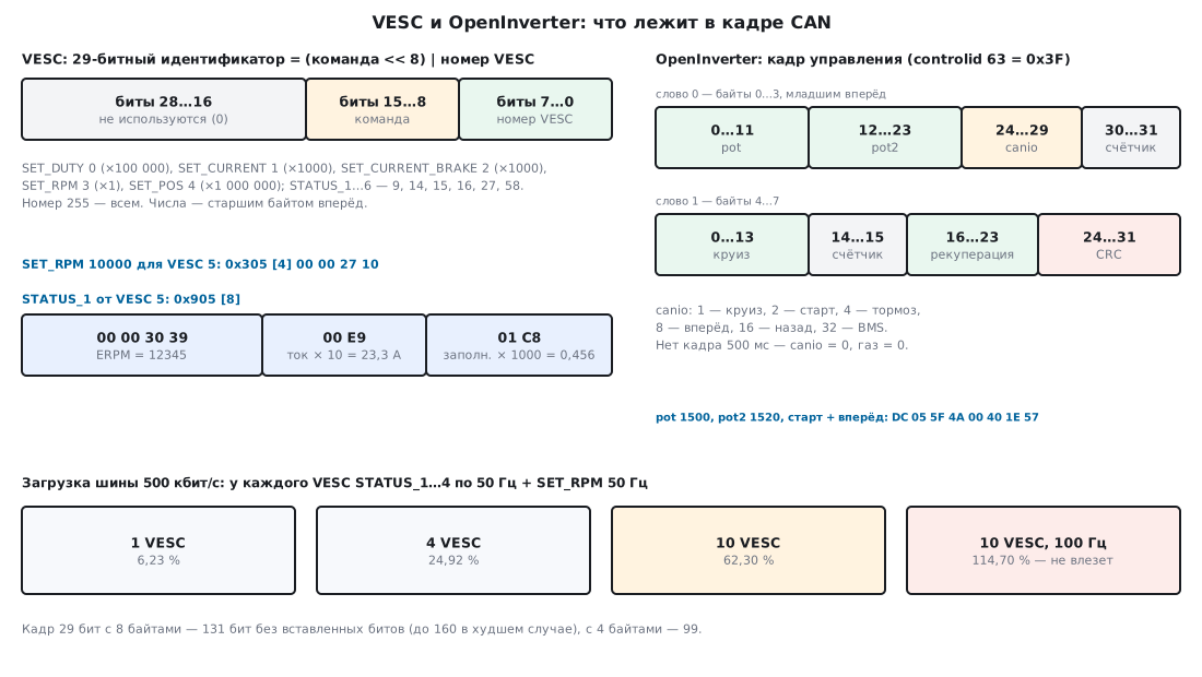
VESC defines a frame for each command. The identifier is 29-bit, with two fields in it: the low byte is the controller number, the next one is the command number. The data are one or two numbers, most significant byte first, with a multiplier. The parsing is hard-coded into the firmware.
OpenInverter sends not commands but parameters. Everything the inverter knows — bus voltage, speed, current limits, throttle — is a numbered row of one database. Which of them go into a frame and where is set by the user with the CAN map; any of them can be read or written with an SDO request. Separately, bypassing the map, there is one control frame — throttle and buttons.
The default VESC bus speed is 500 kbit/s
(APPCONF_CAN_BAUD_RATE); you can also choose 10, 20, 50, 75, 100, 125, 250 and
1000. The prescalers in comm_can.c are calculated for an APB1 clock of 42 MHz (an
8 MHz crystal, PLL to 168 MHz, APB1 = /4, hwconf/mcuconf.h), and all nine
speeds come out exact:
| Speed | Prescaler | Time quanta per bit | Sample point |
|---|---|---|---|
| 1000 kbit/s | 3 | 14 | 78.6 % |
| 500 kbit/s | 6 | 14 | 78.6 % |
| 250 kbit/s | 8 | 21 | 76.2 % |
| 125 kbit/s | 16 | 21 | 76.2 % |
| 10…100 kbit/s | 300…30 | 14 | 85.7 % |
OpenInverter offers 125, 250, 500, 800 kbit/s and 1 Mbit/s (the parameter
canspeed, 500 kbit/s by default).
57в.2 VESC: a command in a single frame
The command number comes from the CAN_PACKET_ID enumeration in datatypes.h, the multiplier
from the comm_can_set_* functions in comm_can.c:
| Command | Number | What | Multiplier | The receiver calls |
|---|---|---|---|---|
| SET_DUTY | 0 | duty cycle −1…1 | 100000 | mc_interface_set_duty |
| SET_CURRENT | 1 | motor current, A | 1000 | mc_interface_set_current |
| SET_CURRENT_BRAKE | 2 | braking current, A | 1000 | mc_interface_set_brake_current |
| SET_RPM | 3 | speed, ERPM | 1 | mc_interface_set_pid_speed |
| SET_POS | 4 | angle, degrees | 1000000 | mc_interface_set_pid_pos |
The number is a signed 32-bit value, most significant byte first (buffer_append_int32).
The identifier is (command << 8) | number. Frames from the run: a VESC function
sends, the decode_msg branch of the same file parses.
| Command | Frame | The receiver got |
|---|---|---|
| SET_RPM 10000 for VESC 5 | 0x305 [4] 00 00 27 10 |
set_pid_speed(10000) |
| SET_RPM −5000 for VESC 5 | 0x305 [4] FF FF EC 78 |
set_pid_speed(−5000) |
| SET_CURRENT 51 A for VESC 23 | 0x117 [4] 00 00 C7 38 |
set_current(51) |
| SET_DUTY 0.25 for VESC 5 | 0x005 [4] 00 00 61 A8 |
set_duty(0.25) |
| SET_CURRENT_BRAKE 10 A for VESC 5 | 0x205 [4] 00 00 27 10 |
set_brake_current(10) |
| SET_POS 90° for VESC 5 | 0x405 [4] 05 5D 4A 80 |
set_pid_pos(90) |
The frame for 51 A on VESC 23 matches the example from the description
comm_can.md — 0x0117, 00 00 C7 38. An independent packer of our own
(Python, struct.pack(">i", …)) produced the same six frames.
A command is accepted by the VESC whose number is in the frame, and by all of them if the number is
255. In the run, VESC 5 ignored SET_RPM for VESC 6 (the motor was not
touched, the timeout was not reset) and executed SET_RPM 3000 for number 255
(frame 0x3FF). Every accepted command resets the communication timeout
(timeout_reset(), 57в.6).
SET_RPM is electrical speed. The VESC speed controller works in
ERPM; VESC gets the shaft speed itself by dividing by the number of pole pairs
(mc_interface_get_rpm() / (conf->si_motor_poles / 2.0) in
motor/mc_interface.c). For a motor with 14 poles (7 pairs), 10000 ERPM
is 10000 / 7 ≈ 1429 rpm at the shaft.
57в.3 VESC: status frames and several controllers
VESC reports about itself in six frames. The numbers and contents come from
comm_can_send_status1…6 and the description:
| Frame | Number | Bytes 0–3 | Bytes 4–5 | Bytes 6–7 |
|---|---|---|---|---|
| STATUS_1 | 9 | ERPM | motor current × 10 | duty cycle × 1000 |
| STATUS_2 | 14 | Ah consumed × 10000 | Ah charged × 10000 (4 bytes) | |
| STATUS_3 | 15 | Wh consumed × 10000 | Wh charged × 10000 (4 bytes) | |
| STATUS_4 | 16 | switch t × 10, motor t × 10 | battery current × 10 | position × 50 |
| STATUS_5 | 27 | tachometer | voltage × 10 | reserved |
| STATUS_6 | 58 | ADC1 × 1000, ADC2 × 1000 | ADC3 × 1000 | PWM input × 1000 |
The frames are grouped into two sets, each with its own rate: by default
50 Hz and 5 Hz (APPCONF_CAN_STATUS_RATE_1/2), and the sets themselves are
empty (APPCONF_CAN_STATUS_MSGS_R1/R2 = 0). A new VESC is silent on the bus
until statuses are enabled for it. The auto-setup command
CAN_PACKET_DETECT_APPLY_ALL_FOC with a flag puts
frames 1–4 into the first set (0b00001111).
Parsing STATUS_1 from the run: VESC 5 with a speed of 12345.6, a current of 23.4 A and
a duty cycle of 0.456 sent 0x905 [8] 00 00 30 39 00 E9 01 C8, and the receiver
read 12345 ERPM, 23.3 A, 0.456. Losing a tenth is not a bus
error: 23.4 as a float is 23.399 999 6…, and after multiplying by 10 and
converting to an integer (by dropping the fractional part) 233 remains. The second
frame — −800 ERPM, −7.25 A, −0.0999: FF FF FC E0 FF B8 FF 9D, the receiver
read −800, −7.2 A and −0.099 — here too the fraction is truncated toward
zero. Our own parser in Python gave the same numbers.
How many controllers the receiver remembers. VESC accepts status frames
from any number (they are parsed outside the "is this frame for me?" check) and
stores them in a table of CAN_STATUS_MSGS_TO_STORE = 10 slots. In the run
the receiver got STATUS_1 from 12 different VESCs — all 10 slots were taken,
the last one stored was number 18; nothing remained from numbers 19 and 20.
57в.4 VESC: a long command in pieces
Everything the VESC serial port can do (reading settings, the
COMM_GET_VALUES telemetry, firmware update) can also be sent over CAN. For
this comm_can_send_buffer() has four service commands:
| Command | Number | Frame data |
|---|---|---|
| PROCESS_SHORT_BUFFER | 8 | sender number, reply mode, up to 6 bytes of the command |
| FILL_RX_BUFFER | 5 | offset (1 byte), up to 7 bytes |
| FILL_RX_BUFFER_LONG | 6 | offset (2 bytes), up to 6 bytes |
| PROCESS_RX_BUFFER | 7 | sender number, reply mode, length (2 bytes), CRC16 (2 bytes) |
A command of up to 6 bytes goes in one frame. A longer one goes in pieces of 7 bytes with
a one-byte offset while the offset is not greater than 255; after that in pieces of 6 bytes with
a two-byte one; last comes the "process" frame with the length and CRC16 (the table
crc16_tab from crc.c, the same as for the serial port). The receiver
puts the pieces into one of three buffers of 512 bytes
(RX_BUFFER_NUM, PACKET_MAX_PL_LEN), checks the length and the CRC, and only
then executes the command. The sender number is remembered — the reply will go back to it the same
way. The run, VESC 2 sends to VESC 5:
| Command, bytes | Frames | Of which |
|---|---|---|
| 5 | 1 | 1 SHORT |
| 6 | 1 | 1 SHORT |
| 7 | 2 | 1 FILL + 1 PROCESS |
| 20 | 4 | 3 FILL + 1 PROCESS |
| 259 | 38 | 37 FILL + 1 PROCESS |
| 300 | 45 | 37 FILL + 7 FILL_LONG + 1 PROCESS |
| 512 | 81 | 37 FILL + 43 FILL_LONG + 1 PROCESS |
In all cases the receiver assembled the command byte for byte. 37 frames of 7 bytes
are 259 bytes: the last one-byte offset is 252. The 20-byte command
ended with the frame 0x705 [6] 02 00 00 14 F2 1A: from VESC 2, mode 0,
length 0x0014 = 20, CRC16 0xF21A.
57в.5 OpenInverter: parameters, the CAN map and SDO
Parameter database. In the stm32-sine param_prj.h, each row is a
category, name, unit, limits, default value and a permanent
number: udcsw (contactor switch-on voltage, 330 V, number 20),
ocurlim (current limit, 100 A, number 22), nodeid (node number, 1),
controlid (control frame identifier, 63). Measured values are
also database rows: udc (bus voltage, number 2001), speed (2012),
tmphs (switch temperature, 2019). Values are stored in fixed
point: 5 fractional bits (FRAC_DIGITS 5 in my_fp.h), that is a step of 1/32.
The CAN map — CanMap::AddSend() and AddRecv(): parameter,
identifier, start bit, length in bits, multiplier, offset. A length with
a minus sign means big-endian order. Sending computes
value × multiplier + offset, receiving computes (bits + offset) × multiplier.
A run with the stm32-sine database:
| Map entry | Value | In the frame |
|---|---|---|
udc → 0x101, bits 0…15, ×10 |
358.7 V | 02 0E — 3586 |
speed → 0x101, bits 16…31, ×1 |
3000 | B8 0B |
tmphs → 0x101, bits 32…39, ×1, offset +40 |
45 °C | 55 — 85 |
speed → 0x102, start 15, length −16 |
3000 | 0B B8 |
Frame 0x101 went out 5 bytes long — exactly up to the last used bit.
The voltage of 358.7 V went out as 3586, not 3587: in the database it is already 358.6875 —
the nearest multiple of 1/32 below — and packing truncates the fraction.
Limits from the Add() code: length up to 32 bits, bit no further than 63, identifier
no greater than 0x7FF (without CAN_EXT); in the run, length 33 gave error −3,
start 60 with length 8 gave −2, identifier 0x800 gave −1. Messages to
send — no more than 10 (MAX_MESSAGES, the eleventh is error −4),
entries in the whole map — no more than 50 (MAX_ITEMS).
Receiving: the entry pot ← 0x200, bits 0…11 and idc ← 0x200, bits 16…31,
multiplier 0.1. The frame D0 07 F4 01 … gave pot 2000 and idc 50.0 A. The frame
D0 07 18 FC …, where the sender meant −100.0 A (0xFC18 = −1000),
gave 6453.6 A: by default CAN_SIGNED = 0, and the receiver reads the bits
as an unsigned number.
How often the map is sent on the bus is set by canperiod: once every 100 ms
(the default) or once every 10 ms.
SDO. The request goes to 0x600 + nodeid, the response comes from 0x580 + nodeid, that is
0x601 and 0x581 by default. Index 0x2100 + the high byte of the number and
subindex = the low byte address a parameter by its permanent number; index 0x2000
with a subindex addresses it by its position in the list, and that depends on the build (in the FOC variant
udcsw is at position 82). The run:
| Request to 0x601 | Response from 0x581 | What |
|---|---|---|
40 00 21 14 00 00 00 00 |
43 00 21 14 40 29 00 00 |
read udcsw: 0x2940 = 10560 = 330 × 32 |
23 00 21 16 80 0C 00 00 |
60 00 21 16 80 0C 00 00 |
write ocurlim = 3200 / 32 = 100 A |
23 00 21 16 00 00 40 00 |
80 00 21 16 30 00 09 06 |
131072 A — above the limit of 65536: abort 0x06090030 |
The inverter with nodeid 1 ignored a request to 0x602 (node 2) — there was no response.
The map can also be edited over SDO: indices 0x3000 (send) and 0x3001
(receive) in cansdo.cpp.
57в.6 Inverter control, a remote on the F103 and timeouts
The OpenInverter control frame is received on controlid (by default
63 = 0x3F) and parsed in VehicleControl::CanReceive(), bypassing the map. Fields
(bits of words, bytes 0–3 and 4–7 little-endian):
| Word | Bits | Field |
|---|---|---|
| 0 | 0…11 | pot — throttle, channel 1 |
| 0 | 12…23 | pot2 — throttle, channel 2 |
| 0 | 24…29 | canio: 1 cruise, 2 start, 4 brake, 8 forward, 16 reverse, 32 BMS |
| 0 | 30…31 | counter |
| 1 | 0…13 | cruise speed |
| 1 | 14…15 | the same counter once more |
| 1 | 16…23 | regen, % |
| 1 | 24…31 | CRC |
Throttle is taken from the frame only if CAN mode is enabled in potmode.
The CRC is the low byte of the CRC-32 of the STM32 CRC unit over the two words with the CRC
byte zeroed (controlcheck = 1 by default; 0 means counter only).
The function FillInCanData from the project test test_vcu.cpp built the frame
"throttle 1500 and 1520, start + forward, regen 30": counter 1 —
DC 05 5F 4A 00 40 1E 57, counter 2 — DC 05 5F 8A 00 80 1E F2. Our own
CRC calculation in Python gave the same CRC bytes 0x57 and 0xF2.
The counter protects against a hung sender: the two counter fields must match, and the counter itself must change from the previous frame. A wrong CRC or counter is an error; while there are fewer than 5 errors, good frames clear them, and after the fifth the inverter does not accept frames until restart.
Contactors and start. At power-up stm32-sine closes the precharge
relay. The main contactor closes when the bus voltage is not below
udcsw, the throttle is released, there are no faults and "start" has arrived — by a pin or by a bit of
canio. If 5 s after power-up (PRECHARGE_TIMEOUT 500 ticks
of 10 ms) the precharge relay is still closed and the voltage is below udcsw / 2, that is a
precharge error and the relay opens.
Direction is set by the "forward" and "reverse" bits; both at once with charging mode
enabled switch the inverter to charging.
Timeouts. Both projects stop the motor if commands stop arriving:
| VESC | OpenInverter | |
|---|---|---|
| What counts as a command | any SET_* over CAN (timeout_reset()) |
the control frame |
| Timeout | APPCONF_TIMEOUT_MSEC 1000 ms; in comm_can.md — 0.5 s |
CAN_TIMEOUT 50 RTC ticks = 500 ms |
| What it does | braking current timeout_brake_current (default 0 — the motor is released) |
canio = 0, throttle = 0, error ERR_CANTIMEOUT |
| Check | a thread every 10 ms | when polling the inputs and the throttle |
For VESC the default value in the code and in the description differ — you have to look at the settings of your own unit. The description recommends sending the command continuously at a constant rate, for example 50 Hz. The same timeout thread feeds the IWDG watchdog (a reset if the motor or CAN thread hangs for longer than 12 ms).
A remote on the STM32F103. The file vesc57v_f103.c: bxCAN at 500 kbit/s,
SET_RPM to controller 5 every 20 ms, and the filter passes only the 29-bit
0x905 (its STATUS_1). If there is no status for longer than 300 ms, the remote sends 0 ERPM:
static int vesc_set_rpm(uint8_t id, int32_t erpm)
{
    uint8_t b[4] = {(uint8_t)(erpm >> 24), (uint8_t)(erpm >> 16), (uint8_t)(erpm >> 8), (uint8_t)erpm};
    return send_eid(((uint32_t)CAN_PACKET_SET_RPM << 8) | id, b, 4);
}
CAN1->sTxMailBox[box].TIR = (eid << 3) | CAN_TI0R_IDE | CAN_TI0R_TXRQ;
Build with arm-none-eabi-gcc 12.2 (-Os, -Wall -Wextra -Werror) — no
warnings: 1252 bytes of flash (1248 of code and 4 of data) and
24 bytes of RAM; main is 472 bytes, the receive interrupt 132.
Bus load. A 29-bit frame with 8 bytes is 131 bits without
stuff bits (including the interframe space), up to 160 in the worst case;
with 4 bytes — 99 and 120 (canframelen.c). The real STATUS_1 from the run
took 142 bits, SET_RPM 107. Each VESC sends STATUS_1…4 at rate f,
and the remote sends SET_RPM to each at 50 Hz; the bus is 500 kbit/s:
| VESC | f | Frames per second | Load | Worst case |
|---|---|---|---|---|
| 1 | 50 Hz | 250 | 6.23 % | 7.60 % |
| 4 | 50 Hz | 1000 | 24.92 % | 30.40 % |
| 10 | 50 Hz | 2500 | 62.30 % | 76.00 % |
| 4 | 100 Hz | 1800 | 45.88 % | 56.00 % |
| 10 | 100 Hz | 4500 | 114.70 % | 140.00 % |
Ten controllers at 50 Hz already take more than half of the bus; at 100 Hz they do not fit at all — frames with higher command numbers (STATUS_4) will lose arbitration and be late.
Galvanic isolation and termination resistors. The power stage of the inverter runs at hundreds of volts; the CAN transceivers of the remote and the control unit are connected to its ground through the bus. The isolation goes between the logic of the inverter and the CAN line (an isolated transceiver and a separate supply for its side), the termination resistors at the two ends of the bus (section 19). Neither VESC nor stm32-sine describe isolation circuits in their sources; this has not been verified here.
57в.7 Full code of the remote and our own encoders
The section has two pieces of its own code: the remote for the VESC on the STM32F103 —
vesc57v_f103.c with the linker script f103.ld — and an independent encoder and
decoder in Python that were used to check the frames of both firmwares. They are given
in full below; the pieces from 57в.6 are repeated here inside their functions. The VESC and
OpenInverter code belongs to others (the licenses are at the start of the section) and is not reproduced here;
the stubs the check uses to build it on a computer are needed only for the
run and are not reproduced here.
The remote is built with the same command as in the check. CMSIS_F1 is the
Device/Include directory of the Keil pack STM32F1xx_DFP 2.4.1 (it contains stm32f10x.h),
CMSIS_CORE is CMSIS/Core/Include from CMSIS 5.9.0
(github.com/ARM-software/CMSIS_5). No separate startup file is needed:
the vector table and Reset_Handler are in vesc57v_f103.c itself, hence
-nostartfiles:
arm-none-eabi-gcc -mcpu=cortex-m3 -mthumb -Os -std=c99 -Wall -Wextra -Werror -ffunction-sections -fdata-sections \
  -DSTM32F10X_MD -I$CMSIS_F1 -I$CMSIS_CORE vesc57v_f103.c -T f103.ld -nostartfiles --specs=nano.specs \
  -Wl,--gc-sections -o fw.elf
arm-none-eabi-size fw.elf
Settings and state. The CAN prescalers for 500 kbit/s are checked by the
compiler itself (_Static_assert); everything the interrupt writes is volatile:
/* Раздел 57в — пульт для VESC на STM32F103C8: 50 раз в секунду шлёт SET_RPM контроллеру 5
 * и принимает его STATUS_1. Кадры — 29-битные: идентификатор = (команда << 8) | номер VESC,
 * числа — старшим байтом вперёд (как buffer_append_int32 в прошивке VESC).
 *   PB8/PB9 — CAN_RX/CAN_TX после ремапа; кварц 8 МГц × 9 = 72 МГц, APB1 = 36 МГц;
 *   500 кбит/с: 36 МГц / 4 = 9 МГц, 1 + 15 + 2 = 18 квантов, точка выборки 16/18.
 * Если статус от VESC не приходит дольше 300 мс, пульт перестаёт считать связь живой;
 * сам VESC без команд дольше своего тайм-аута отпускает двигатель. */
#include "stm32f10x.h"

#define FCAN     36000000u
#define BRP      4u
#define TS1      15u
#define TS2      2u
_Static_assert(FCAN / (BRP * (1u + TS1 + TS2)) == 500000u, "500 кбит/с ровно");

#define VESC_ID            5u
#define CAN_PACKET_SET_RPM 3u
#define CAN_PACKET_STATUS  9u

static volatile uint32_t ms;
static volatile int32_t erpm_now;     /* из STATUS_1 */
static volatile int16_t current_x10;  /* ток × 10 */
static volatile int16_t duty_x1000;   /* заполнение × 1000 */
static volatile uint32_t last_status_ms;
static volatile uint8_t status_seen;
static volatile int32_t erpm_set = 10000;

void SysTick_Handler(void)
{
    ms++;
}
Sending. The number of a free mailbox comes from the CODE field of the TSR register; the number is sent
most significant byte first, like buffer_append_int32 in VESC:
/* 29-битный кадр в свободный ящик; 0 — все три заняты */
static int send_eid(uint32_t eid, const uint8_t *d, uint32_t len)
{
    uint32_t box = (CAN1->TSR & CAN_TSR_CODE) >> 24;
    uint32_t lo = 0, hi = 0;
    if ((CAN1->TSR & (CAN_TSR_TME0 << box)) == 0u) {
        return 0;
    }
    for (uint32_t i = 0; i < len; i++) {
        if (i < 4u) lo |= (uint32_t)d[i] << (8u * i);
        else        hi |= (uint32_t)d[i] << (8u * (i - 4u));
    }
    CAN1->sTxMailBox[box].TDTR = len;
    CAN1->sTxMailBox[box].TDLR = lo;
    CAN1->sTxMailBox[box].TDHR = hi;
    CAN1->sTxMailBox[box].TIR = (eid << 3) | CAN_TI0R_IDE | CAN_TI0R_TXRQ;
    return 1;
}

static int vesc_set_rpm(uint8_t id, int32_t erpm)
{
    uint8_t b[4] = {(uint8_t)(erpm >> 24), (uint8_t)(erpm >> 16), (uint8_t)(erpm >> 8), (uint8_t)erpm};
    return send_eid(((uint32_t)CAN_PACKET_SET_RPM << 8) | id, b, 4);
}
Receiving STATUS_1. The filter passes only 0x905, but the interrupt checks
the identifier once more; the bytes from RDLR and RDHR are rearranged into
big-endian order:
void USB_LP_CAN1_RX0_IRQHandler(void)
{
    while (CAN1->RF0R & CAN_RF0R_FMP0) {
        uint32_t rir = CAN1->sFIFOMailBox[0].RIR;
        uint32_t lo = CAN1->sFIFOMailBox[0].RDLR, hi = CAN1->sFIFOMailBox[0].RDHR;
        uint32_t eid = rir >> 3;
        if ((rir & CAN_RI0R_IDE) && eid == (((uint32_t)CAN_PACKET_STATUS << 8) | VESC_ID)) {
            /* байты 0–3 — ERPM, 4–5 — ток × 10, 6–7 — заполнение × 1000, старшим вперёд */
            erpm_now = (int32_t)(((lo & 0xFFu) << 24) | ((lo & 0xFF00u) << 8) | ((lo >> 8) & 0xFF00u) | (lo >> 24));
            current_x10 = (int16_t)(((hi & 0xFFu) << 8) | ((hi >> 8) & 0xFFu));
            duty_x1000 = (int16_t)(((hi >> 8) & 0xFF00u) | (hi >> 24));
            last_status_ms = ms;
            status_seen = 1;
        }
        CAN1->RF0R = CAN_RF0R_RFOM0;
    }
}
Clocks and bxCAN. An 8 MHz crystal × 9 = 72 MHz, APB1 = 36 MHz; CAN on PB8/PB9 through the remap; filter 0 is a mask on all 29 identifier bits and the IDE bit:
static void clock_72mhz(void)
{
    RCC->CR |= RCC_CR_HSEON;
    while (!(RCC->CR & RCC_CR_HSERDY)) {
    }
    FLASH->ACR = FLASH_ACR_PRFTBE | FLASH_ACR_LATENCY_2;
    RCC->CFGR = RCC_CFGR_PLLSRC | RCC_CFGR_PLLMULL9 | RCC_CFGR_PPRE1_DIV2;
    RCC->CR |= RCC_CR_PLLON;
    while (!(RCC->CR & RCC_CR_PLLRDY)) {
    }
    RCC->CFGR |= RCC_CFGR_SW_PLL;
    while ((RCC->CFGR & RCC_CFGR_SWS) != RCC_CFGR_SWS_PLL) {
    }
}

static void can_init(void)
{
    RCC->APB2ENR |= RCC_APB2ENR_IOPBEN | RCC_APB2ENR_AFIOEN;
    RCC->APB1ENR |= RCC_APB1ENR_CAN1EN;
    AFIO->MAPR |= AFIO_MAPR_CAN_REMAP_REMAP2;                 /* CAN на PB8/PB9 */
    GPIOB->CRH = (GPIOB->CRH & ~0xFFu) | 0x4u | (0xBu << 4);  /* PB8 вход, PB9 альт. выход 50 МГц */

    CAN1->MCR = CAN_MCR_INRQ | CAN_MCR_ABOM;
    while (!(CAN1->MSR & CAN_MSR_INAK)) {
    }
    CAN1->BTR = ((TS2 - 1u) << 20) | ((TS1 - 1u) << 16) | (BRP - 1u);

    CAN1->FMR |= CAN_FMR_FINIT;
    CAN1->FA1R &= ~1u;
    CAN1->FS1R |= 1u;                                         /* один 32-битный фильтр */
    CAN1->FM1R &= ~1u;                                        /* режим маски */
    CAN1->sFilterRegister[0].FR1 = (((uint32_t)CAN_PACKET_STATUS << 8 | VESC_ID) << 3) | CAN_RI0R_IDE;
    CAN1->sFilterRegister[0].FR2 = (0x1FFFFFFFu << 3) | CAN_RI0R_IDE;   /* ровно 0x905, только 29 бит */
    CAN1->FFA1R &= ~1u;
    CAN1->FA1R |= 1u;
    CAN1->FMR &= ~CAN_FMR_FINIT;

    CAN1->IER = CAN_IER_FMPIE0;
    NVIC_EnableIRQ(USB_LP_CAN1_RX0_IRQn);
    CAN1->MCR &= ~CAN_MCR_INRQ;
    while (CAN1->MSR & CAN_MSR_INAK) {
    }
}
Main loop. SET_RPM every 20 ms; no status for longer than 300 ms — 0 ERPM:
int main(void)
{
    uint32_t next = 0;

    clock_72mhz();
    SysTick_Config(72000u);                   /* 1 мс */
    can_init();

    for (;;) {
        if ((int32_t)(ms - next) >= 0) {      /* 50 Гц: команду повторять, иначе VESC отпустит двигатель */
            next = ms + 20u;
            int link_ok = status_seen && (ms - last_status_ms) < 300u;
            (void)vesc_set_rpm(VESC_ID, link_ok ? erpm_set : 0);
        }
    }
}
Startup and the vector table. Copying .data, zeroing .bss, entering
main; the table holds the top of the stack, reset, SysTick (vector 15) and the CAN
receive interrupt (16 + 20):
extern uint32_t _estack, _sidata, _sdata, _edata, _sbss, _ebss;

void Reset_Handler(void)
{
    uint32_t *src = &_sidata, *dst = &_sdata;
    while (dst < &_edata) {
        *dst++ = *src++;
    }
    for (dst = &_sbss; dst < &_ebss;) {
        *dst++ = 0;
    }
    main();
    for (;;) {
    }
}

void Default_Handler(void)
{
    for (;;) {
    }
}

typedef void (*vector_t)(void);

__attribute__((section(".isr_vector"), used))
const vector_t vectors[16 + 21] = {
    [0] = (vector_t)&_estack, [1] = Reset_Handler, [2] = Default_Handler, [3] = Default_Handler,
    [15] = SysTick_Handler, [16 + 20] = USB_LP_CAN1_RX0_IRQHandler,
};
Linker script. 64 KB of flash, 20 KB of RAM and 2 KB for the stack:
/* Раздел 57в: STM32F103C8 — 64 КБ флеш-памяти, 20 КБ ОЗУ. */
ENTRY(Reset_Handler)

MEMORY
{
  FLASH (rx)  : ORIGIN = 0x08000000, LENGTH = 64K
  RAM   (rwx) : ORIGIN = 0x20000000, LENGTH = 20K
}

_estack     = ORIGIN(RAM) + LENGTH(RAM);
_stack_size = 0x800;

SECTIONS
{
  .isr_vector : { KEEP(*(.isr_vector)) } > FLASH
  .text :
  {
    *(.text .text.*)
    *(.rodata .rodata.*)
    . = ALIGN(4);
  } > FLASH
  .data :
  {
    _sdata = .;
    *(.data .data.*)
    . = ALIGN(4);
    _edata = .;
  } > RAM AT > FLASH
  _sidata = LOADADDR(.data);
  .bss (NOLOAD) :
  {
    _sbss = .;
    *(.bss .bss.*)
    *(COMMON)
    . = ALIGN(4);
    _ebss = .;
  } > RAM
  ASSERT(_ebss + _stack_size <= _estack, "RAM too small for .data + .bss + stack")
}
Our own VESC encoder and decoder in Python. A command is the identifier
(command << 8) | number and the number struct.pack(">i", …); STATUS_1 is
struct.unpack(">ihh", …). Apart from import struct, nothing is needed:
CMD = {"SET_DUTY": (0, 100000), "SET_CURRENT": (1, 1000), "SET_CURRENT_BRAKE": (2, 1000), "SET_RPM": (3, 1), "SET_POS": (4, 1000000)}


def vesc_cmd(name, vesc, value):
    cmd, scale = CMD[name]
    return (cmd << 8) | vesc, struct.pack(">i", int(value * scale))


def vesc_status1(data):
    erpm, cur, duty = struct.unpack(">ihh", data)
    return erpm, cur / 10.0, duty / 1000.0
The OpenInverter control frame. The CRC is the same as the STM32 CRC unit: polynomial 0x04C11DB7, initial value 0xFFFFFFFF, over 32-bit words, most significant bit first; the low byte goes into the frame:
def stm32_crc(words):
    crc = 0xFFFFFFFF
    for w in words:
        crc ^= w
        for _ in range(32):
            crc = ((crc << 1) ^ 0x04C11DB7) & 0xFFFFFFFF if crc & 0x80000000 else (crc << 1) & 0xFFFFFFFF
    return crc


def oi_control(pot, pot2, canio, cruise, regen, seq):
    w0 = pot | (pot2 << 12) | (canio << 24) | (seq << 30)
    w1 = cruise | (seq << 14) | (regen << 16)
    w1 |= (stm32_crc([w0, w1]) & 0xFF) << 24
    return w0, w1
The output of these functions in the run gives the same bytes and numbers as the firmwares (57в.2, 57в.3, 57в.6):
PY SET_RPM 10000 для 5: 00000305 [4] 00 00 27 10
PY SET_RPM -5000 для 5: 00000305 [4] FF FF EC 78
PY SET_CURRENT 51 для 23: 00000117 [4] 00 00 C7 38
PY SET_DUTY 0.25 для 5: 00000005 [4] 00 00 61 A8
PY SET_CURRENT_BRAKE 10 для 5: 00000205 [4] 00 00 27 10
PY SET_POS 90 для 5: 00000405 [4] 05 5D 4A 80
PY STATUS_1 00 00 30 39 00 E9 01 C8: ERPM 12345, ток 23.3 А, заполнение 0.456
PY STATUS_1 FF FF FC E0 FF B8 FF 9D: ERPM -800, ток -7.2 А, заполнение -0.099
PY CTRL seq 1: 4A5F05DC 571E4000, байты DC 05 5F 4A 00 40 1E 57
PY CTRL seq 2: 8A5F05DC F21E8000, байты DC 05 5F 8A 00 80 1E F2
PY CTRL разбор: pot 1500, pot2 1520, canio 10, ctr1 1, cruise 0, ctr2 1, regen 30, crc 57
57в.8 Pitfalls
VESC does not respond and sends no status. The status sets are empty by default
(APPCONF_CAN_STATUS_MSGS_R1/R2 = 0). Enable the frames in the settings or
with auto-setup with the flag.
The motor jerks and stops. The command arrived once, and after the timeout VESC released the motor. Send the command continuously, for example at 50 Hz — the VESC description recommends this too.
A six-byte SET_CURRENT gives a monstrous current. In this version
comm_can_set_current_off_delay() puts the current into bytes 0–3 and the delay into
4–5, while the parse branch for a length of 6 or more first reads the delay from bytes
0–1, then the current from 2–5. In the run, "20 A, delay 0.5 s"
(00 00 4E 20 01 F4) turned into a delay of 0 and a current of 1310720.5 A;
according to the VESC description, a value outside the limit is clamped to the limit — that is, to
the maximum current. Send the four-byte SET_CURRENT; the six-byte one only
after checking it on your own firmware version.
The current in the status is 0.1 A lower. Packing ×10 truncates the fraction: 23.4 A arrived as 23.3, −7.25 A as −7.2.
The eleventh VESC disappeared. The receiver's status table has 10 slots.
A negative OpenInverter current became 6453.6 A. By default the map
reads the bits as unsigned (CAN_SIGNED = 0). Build libopeninv with
CAN_SIGNED = 1 or send the value with an offset.
358.7 V went out as 358.6. The database stores values in steps of 1/32, and packing truncates the fraction.
SDO at 0x2000 reads the wrong parameter. The subindex there is the position in the list, and it differs between firmware variants. Use 0x21xx with the permanent number.
The inverter stopped obeying until restart. Five counter or CRC errors in the control frame in a row without good frames — and it no longer accepts control. Change the counter in every frame, both fields the same.
The bus is choking. STATUS_1…4 at 100 Hz from ten VESCs is 114.70 % of a 500 kbit/s bus. Keep only STATUS_1 in the fast set and move the rest to the slow set at 5 Hz.
57в.9 Summary
- VESC: the 29-bit identifier =
(command << 8) | number, 255 means all; SET_RPM 10000 for VESC 5 is0x305 00 00 27 10. - Multipliers: duty cycle ×100000, current ×1000, speed ×1, angle ×1000000; in STATUS_1 — current ×10, duty cycle ×1000, the fraction is truncated.
- Statuses are off by default; the set rates are 50 and 5 Hz; the receiver remembers 10 controllers.
- A long command: up to 6 bytes is 1 frame, 512 bytes is 81 frames with CRC16.
- OpenInverter: parameters in steps of 1/32, the map holds up to 10 messages and 50 entries, SDO at 0x601/0x581, the control frame at 0x3F with CRC and a counter.
- Timeouts: VESC — 1000 ms in the code (0.5 s in the description), OpenInverter — 500 ms; send commands continuously.
- 10 VESCs with statuses 1–4 at 50 Hz take 62.30 % of a 500 kbit/s bus.
- The remote on the F103 is 1252 bytes of flash.
Next: section 57г "Klipper: STM32 as the executor of a 3D printer — steps on a schedule from the host" — the stepper motors of a 3D printer: the computer calculates the step times, the STM32 executes the schedule.