 Embedded HandbookApps
57г. Klipper: STM32 as the executor of a 3D printer — steps on a schedule from the host
In section 57а the microcontroller accelerated the stepper motor by itself: the interval between steps was computed in an interrupt with a recurrence formula. That is how printer firmware such as Marlin works — everything, from G-code parsing to kinematics, lives in one STM32. In 57в the motor commands already came over CAN from another unit.
Klipper splits the work differently. Everything complex — G-code parsing, velocity planning, kinematics, smoothing — is computed by a Linux computer (usually a single-board one), the host. It knows the moment of every step to within one tick of the microcontroller's timer and sends a ready-made schedule. The STM32 only executes it: "step after so many ticks, then so many more times with such-and-such interval increment". This section covers how that schedule is compressed, how the protocol works, how the two devices agree on time and what changes when the board sits on the print head and is connected over CAN.
Sources: the Klipper source code (commit 7bc4d09). MCU side —
src/command.c, src/sched.c, src/stepper.c, src/endstop.c,
src/trsync.c, src/generic/armcm_timer.c, src/stm32/stm32f0_timer.c,
src/generic/canserial.c, src/generic/usb_canbus.c, src/stm32/Kconfig;
host — klippy/chelper/stepcompress.c, msgblock.c, serialqueue.c,
itersolve.c, trapq.c, kin_cartesian.c, klippy/clocksync.py,
klippy/stepper.py, klippy/serialhdl.py, klippy/extras/homing.py,
klippy/extras/canbus_ids.py. The code is not retold from memory: the real
trapq.c, itersolve.c, kin_cartesian.c, stepcompress.c and msgblock.c
computed the steps of a move and compressed them, the real src/command.c with
crc16_ccitt.c parsed the byte stream the way the microcontroller does, and the whole firmware
was built for five STM32 variants. The run is _verify/klip57g/klip57g.py,
the record is _verify/klip57g/klip57g_host.txt. License: Klipper — GPL-3.0
(file COPYING; the file headers say "GNU GPLv3 license", © Kevin O'Connor).
Terms used in the documentation
Term Meaning host, klippy the computer and the program running on it MCU, micro-controller the microcontroller, the executor print time, clock print time (seconds), MCU timer ticks message block, sequence number a message block, its number VLQ (variable length quantity) a variable-length integer ACK / NAK acknowledgement / request to resend data dictionary, identify data dictionary, identifying the MCU on connection step compression, max error step compression, allowed error of a step moment queue_step interval count add command "count steps, the first after interval, the interval changes by add" clock synchronization syncing the host clock with the MCU clock endstop, homing, trsync limit switch, search for zero, trigger synchronization toolhead board, CAN bridge board on the print head, USB-to-CAN bridge
57г.1 Who computes what
The firmware on the STM32 knows nothing about G-code, millimetres or accelerations. It
has numbered objects (oid): a stepper motor, an endstop, a heater, a
sensor. On connection the host configures them with commands such as
config_stepper oid=%c step_pin=%c dir_pin=%c …, and after that sends
commands with moments expressed in MCU timer ticks.
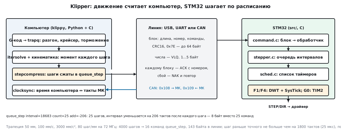
On the host motion lives in the trapq queue as segments with constant
acceleration. For each motor itersolve.c with the kinematics (Cartesian,
CoreXY, delta…) finds the moments when the axis position crosses the next
step boundary — in floating point, in seconds. stepcompress.c converts
them into MCU ticks and packs them into queue_step commands.
On the microcontroller command.c parses the block and calls the handler.
command_queue_step puts the triple "interval, count, add" into the motor's queue
(stepper.c), and the step itself is made by the timer handler: it raises the STEP pin,
adds the interval, increases the interval by add and sets the timer again. All
timers are one sorted list in sched.c; the interrupt takes the first one
from the list and reschedules it.
Time. Klipper needs a free-running 32-bit counter, not a periodic interrupt:
| Family | Time counter | Interrupt | Frequency in the build |
|---|---|---|---|
| STM32F1, F4 (Cortex-M3/M4) | DWT->CYCCNT — core clock cycles | SysTick for the gap to the next timer | 72 MHz (F103), 168 MHz (F407) |
| STM32G0 (Cortex-M0+, no DWT) | TIM2, 32 bits | TIM2 channel 1 compare | 64 MHz (G0B1) |
The choice is made in src/stm32/Makefile: for F0 and G0 it takes stm32f0_timer.c,
which uses TIM2 if the chip header has it (in
stm32g0b1xx.h it does), otherwise the 16-bit TIM3. All other STM32 work through
armcm_timer.c. The list of supported chips is in src/stm32/Kconfig: from
F031 and F103 to G0B1, G474, H743 and L412.
57г.2 Protocol: blocks, variable-length numbers, CRC
Commands travel in blocks. The format is defined in src/command.h:
| Byte | What |
|---|---|
| 0 | length of the whole block: from 5 (MESSAGE_MIN) to 64 (MESSAGE_MAX) |
| 1 | 0x10 + block number 0…15 (MESSAGE_DEST, MESSAGE_SEQ_MASK) |
| 2…n−4 | commands back to back: command number and parameters |
| n−3, n−2 | CRC16, most significant byte first |
| n−1 | 0x7E (MESSAGE_SYNC) |
The command number and all integer parameters are variable-length numbers (VLQ):
7 bits per byte, the top bit of a byte means "one more byte follows". The sign is carried without
a separate bit: if bits 6 and 5 of the first byte are 11, the number is
negative. The encoder from src/command.c:
    if (sv < (3L<<5)  && sv >= -(1L<<5))  goto f4;
    if (sv < (3L<<12) && sv >= -(1L<<12)) goto f3;
    if (sv < (3L<<19) && sv >= -(1L<<19)) goto f2;
    if (sv < (3L<<26) && sv >= -(1L<<26)) goto f1;
The run: the host encodes (msgblock.c), the MCU decodes (command_parsef
from command.c):
| Number | Bytes | Length |
|---|---|---|
| 0 | 00 |
1 |
| 95 | 5F |
1 |
| 96 | 80 60 |
2 |
| −32 | 60 |
1 |
| −33 | FF 5F |
2 |
| 1800 | 8E 08 |
2 |
| 12288 | 80 E0 00 |
3 |
| 1572864 | 80 E0 80 00 |
4 |
| 2147483647 | 87 FF FF FF 7F |
5 |
One byte covers −32 to 95, five bytes the largest 32-bit values. All 15 numbers of the run came back unchanged.
CRC16 is crc16_ccitt() with an initial value of 0xFFFF, the same
function on the MCU (src/generic/crc16_ccitt.c) and on the host
(msgblock_crc16_ccitt). For the string "123456789" both gave 0x6F91.
Data dictionary. Command numbers are not hard-wired into the protocol: during the build
scripts/buildcommands.py collects all DECL_COMMAND declarations from the sources,
assigns numbers and puts a zlib-compressed dictionary into the firmware. On
connection the host reads it with the identify command and from then on knows that
queue_step oid=%c interval=%u count=%hu add=%hi is command 22, and that the
timer frequency is the constant CLOCK_FREQ. In all five builds below
queue_step got number 22, set_next_step_dir — 21. The dictionary
of the F103 USB build has 116 commands, 25 responses, 19 constants: 10860 bytes of JSON,
compressed in the firmware to 3746 bytes (command_identify_data).
57г.3 Block numbers, ACK and NAK
For every complete block with a correct CRC and the expected number the MCU replies with an empty
5-byte block carrying the number of the next expected block — that is the ACK. If
the CRC does not match or the number is wrong, the MCU replies with the same kind of block carrying its own
expected number — that is the NAK, and the host resends everything starting from it.
A run through the real command_find_and_dispatch():
| What arrived at the MCU | Result | MCU reply |
|---|---|---|
block seq 1 0B 11 16 00 8E 08 0A 7D BB 4A 7E — a fresh MCU expects seq 0 |
discarded | 05 10 9E 81 7E |
| the same queue_step with seq 0 | executed: 10 steps | 05 11 8F 08 7E |
| seq 1, one byte corrupted | discarded | 05 11 8F 08 7E |
| seq 2 before seq 1 | discarded | 05 11 8F 08 7E |
| seq 1 resent | executed | 05 12 BD 93 7E |
| seq 2 resent | executed, 30 steps in total | 05 13 AC 1A 7E |
The first row is the connection itself: serialqueue.c starts with number 1,
and when it gets a reply to a block it never sent, it adopts the MCU's number as its own
(update_receive_seq, "must be connection init"). Decoding the block
0B 11 16 00 8E 08 0A 7D BB 4A 7E: length 11, number 1, command 22
(queue_step), oid 0, interval 1800 (8E 08), count 10, add −3 (7D), CRC
0xBB4A, 0x7E. Ten steps with interval 1800 and increment −3 end at
tick 10 × 1800 − 3 × 45 = 17865 — exactly what the MCU counted.
57г.4 Step compression: queue_step and max_error
Sending every step as a separate command is expensive. stepcompress.c looks for runs
that can be described by the triple interval, count, add: the first step comes
interval ticks after the previous one, and after that the interval changes by
add each time. The moment of step i (from 1) is interval·i + add·i(i−1)/2: at constant
speed add = 0, during acceleration the interval gets shorter.
An exact match is not required. Each step has an allowed window
(minmax_point in stepcompress.c):
    uint32_t max_error = (point - prevpoint) / 2;
    if (max_error > sc->max_error)
        max_error = sc->max_error;
    return (struct points){ point - max_error, point };
A step may be made earlier than the exact moment, but by no more than
max_error and no more than half the gap to the previous step, and never
later. max_error = MAX_STEPCOMPRESS_ERROR = 25 µs (klippy/stepper.py),
converted to MCU ticks: 1800 at 72 MHz. The function compress_bisect_add()
searches over add by bisection, for each value finds the longest
run that fits all the windows, and takes the one that gets the
furthest; check_line() checks every point once more.
The run. One move along X: 50 mm, speed 100 mm/s, acceleration
3000 mm/s², 80 steps per mm, MCU frequency 72 MHz (F103). Acceleration takes 0.033333 s
(1.6667 mm), cruise 0.466667 s, total 0.533333 s. The real trapq.c,
itersolve.c and kin_cartesian.c produced 4000 steps, stepcompress.c
compressed them into 16 queue_step commands and one set_next_step_dir. The start of
acceleration:
| interval | count | add | Command bytes |
|---|---|---|---|
| 7346969 | 1 | 0 | 16 00 83 C0 B6 19 01 00 |
| 106145 | 2 | −30626 | 16 00 86 BD 21 02 FE 90 5E |
| 58426 | 4 | −5490 | 16 00 83 C8 3A 04 FF D5 0E |
| 38184 | 8 | −1577 | 16 00 82 AA 28 08 F3 57 |
| 26197 | 15 | −533 | 16 00 81 CC 55 0F FB 6B |
| 18683 | 25 | −206 | 16 00 81 91 7B 19 FE 32 |
The first command is one step 7346969 ticks (0.102 s) after the zero moment of counting; after that the runs grow: 2, 4, 8, 15, 25 steps — the smoother the acceleration, the longer the run. At cruise the interval is 9000 ticks = 125 µs, exactly 100 mm/s × 80 steps/mm = 8000 steps/s.
Cross-check. The blocks went through command.c, and the handler reconstructed the moments
the same way stepper.c does. All 4000 steps are in place; earlier than the exact moment
by no more than 1797.259 ticks (tolerance 1800), later by no more than 0.296
ticks: that is the rounding of the exact fractional moment to a whole tick, the compression itself
never shifts a step later.
How many bytes.
| Commands | Command bytes | Blocks | Bytes on the line | |
|---|---|---|---|---|
| no compression (count = 1 for every step) | 4000 | 24144 | ||
| stepcompress | 17 | 128 | 3 | 143 |
Compression is 188.6 times. 143 bytes over UART at 250000 baud
(the default SERIAL_BAUD) take 5.72 ms, over CAN at 1 Mbit/s 19 frames,
2025 bits, 2.02 ms (the calculate_bittime() formula from serialqueue.c), while
the move itself lasts 533.33 ms.
What the number of commands depends on. The same segment at different MCU frequencies and speeds:
| MCU frequency | max_error, ticks | queue_step | Bytes on the line | Earlier, up to ticks | Later, up to ticks |
|---|---|---|---|---|---|
| 64 MHz (G0B1) | 1600 | 17 | 150 | 1600.073 | 0.303 |
| 72 MHz (F103) | 1800 | 16 | 143 | 1797.259 | 0.296 |
| 168 MHz (F407) | 4200 | 18 | 162 | 4200.481 | 0.441 |
| Speed, 72 MHz | queue_step | Command bytes | Bytes on the line |
|---|---|---|---|
| 50 mm/s | 12 | 100 | 110 |
| 100 mm/s | 16 | 128 | 143 |
| 200 mm/s | 24 | 182 | 202 |
| 300 mm/s | 31 | 232 | 257 |
Faster means longer acceleration and deceleration sections, where the runs are shorter. "Earlier" at 64 and 168 MHz is slightly above the tolerance (1600.073 and 4200.481) — this is the same fraction of a tick from rounding the exact moment: the window is counted from a whole tick.
57г.5 Clocks and endstops
The host schedules steps in "print time" — seconds on its own clock. To
convert them into MCU ticks, the two clocks must be linked. That is the job of klippy/clocksync.py:
- on connection — 8
get_clockrequests 50 ms apart, after that — once every 0.9839 s (an "unusual" period, so as not to coincide with other periodic events); - every
clockreply is a 32-bit MCU tick; the host extends it to 64 bits using the difference from the previous one; - the "send time — tick" pairs go into a linear regression with exponential
forgetting: the weight of a new measurement
DECAY= 1/30; the slope is the estimate of the MCU frequency, that is, of its crystal drift; - a measurement that deviates from the prediction by more than 5 sigma and more than 0.5 ms is discarded; separately, the smallest half of the round-trip time is remembered.
stepcompress_set_time() receives the frequency and offset estimate for each
motor: a step moment in seconds becomes a tick as
(time − offset) × frequency. If there are several boards (the main one and one on the head),
each has its own regression, and the same print time is converted into ticks
for each board separately.
If a command is late. Commands are sent in advance: the host keeps
them up to BUFFER_TIME_HIGH = 1 s ahead of execution (klippy/toolhead.py), and the
MCU puts them into the motor's queue. If a command arrives when its time has already passed, the MCU does not
"catch up": sched_add_timer() stops everything with the error "Timer too
close", stepper_load_next() with "Stepper too far in past" (more than 1 ms
late).
Endstop and homing. The host sends endstop_home with the start
moment, the sampling period and the number of confirmations. Sampling is also a timer in
sched.c: endstop_event() reads the pin, on a match switches to
repeated reads every sample_ticks, and only after sample_count
matches in a row calls trsync_do_trigger(). By default
ENDSTOP_SAMPLE_TIME = 15 µs and ENDSTOP_SAMPLE_COUNT = 4
(klippy/extras/homing.py). The trigger stops the motors
subscribed to the same trsync (stepper_stop() clears their queues)
right on the MCU, without waiting for the host. If the endstop is on one board and
the motor on another, the host links them: each board reports that it is
alive; if no message arrives within TRSYNC_TIMEOUT = 25 ms (250 ms if there is only one board),
homing is aborted.
57г.6 CAN, the toolhead board and building the firmware
CAN. A board on the print head (for example, on a G0B1) is connected with a CAN twisted
pair and power instead of a harness to every motor, heater and sensor. The protocol
is the same; the byte stream is cut into 8-byte frames (do_write() in
serialqueue.c, standard 11-bit identifiers). Node numbers
are assigned by the host:
| What | Identifier |
|---|---|
| query "who has no number" and number assignment | 0x3F0 (CANBUS_ID_ADMIN) |
| board reply: 6-byte UUID | 0x3F1 |
| host → board with node number n | n × 2 + 256: for the first n = 4 — 0x108 |
| board → host | one more: 0x109 |
The board UUID is 6 bytes of the fasthash64 hash of the chip's factory serial number
(canserial_set_uuid); it goes into the configuration (canbus_uuid). The first
node number is NODEID_FIRST = 4 (canbus_ids.py). The default speed is
CANBUS_FREQUENCY 1000000.
USB-to-CAN bridge. The main board can be built in
USBCANBUS mode: to Linux it looks like a gs_usb adapter (usb_canbus.c), while
it remains a Klipper node on the same bus itself. The mode exists where the
chip has both USB and CAN: F042/F072, F207, F405/F407/F429, F446, G0B1, G4, H7.
Except STM32F1 — in Kconfig, HAVE_STM32_USBCANBUS has
depends on !MACH_STM32F1: on the F103 USB and CAN share one buffer memory
and do not work together (198е), so you pick one of the two.
Building without a network. Klipper is built with make menuconfig and make. The menu is not needed: a
.config file of two or three lines and make olddefconfig are enough (it lives in lib/kconfiglib
inside the tree, Python 3). For USB on the F103:
CONFIG_MACH_STM32=y
CONFIG_MACH_STM32F103=y
For CAN a pin selection line is added: CONFIG_STM32_CANBUS_PA11_PA12=y
(F103) or CONFIG_STM32_MMENU_CANBUS_PB0_PB1=y (G0B1). Everything else is
the defaults from Kconfig: frequency, memory size, bootloader.
arm-none-eabi-gcc 12.2 in stm-arm:1:
| Build | Frequency | Code (text) | Data | RAM (bss) | klipper.bin |
|---|---|---|---|---|---|
| F103, USB | 72 MHz | 43682 | 52 | 1164 | 43736 |
| F103, CAN (bxCAN) | 72 MHz | 43166 | 52 | 1284 | 43220 |
| F407, USB | 168 MHz | 46410 | 64 | 1220 | 46476 |
| G0B1, USB | 64 MHz | 47540 | 52 | 1160 | 47592 |
| G0B1, CAN (FDCAN) | 64 MHz | 47260 | 52 | 1280 | 47312 |
By default the F103 is built for 64 KB of flash (FLASH_SIZE 0x10000)
with an 8 KB bootloader (firmware from 0x8002000) — 43736 bytes fit into the
remaining 56 KB. The F407 starts at 0x8008000 (32 KB bootloader). Klipper allocates RAM for the command
queues at startup from the remaining memory, which is why bss is small.
The step handler stepper_event_full is 96 bytes on F1/F4 and 82 on G0;
the timer interrupt — SysTick 296 bytes (F103) and 304 (F407), TIM2 on G0B1 —
284; CAN receive — 360 (bxCAN F103) and 328 (FDCAN G0B1).
Two build details on a Windows copy of the tree: the image has no cpp — the linker
script is prepared with make CPP=arm-none-eabi-cpp; scripts/check-gcc.sh
with CRLF line endings does not run ("No such file or directory"). The build
timestamp goes into the dictionary; to get identical sizes from run to
run it is replaced with a constant.
57г.7 Pitfalls
"Timer too close" or "Stepper too far in past" during printing. The MCU received a command whose time has already passed: the host did not keep up (overloaded, a USB hub, a slow memory card) or clock synchronization went wrong. The MCU does not catch up but stops — that is by design.
The tail of the trapq queue "returned" the axis. In a run without a final standstill
itersolve reached the service end of the queue with zero position and
counted 4000 steps back — stepcompress refused: "Invalid sequence" with
a negative interval. In Klipper a move always ends with a standstill; in
your own harness you have to add it yourself.
The first block after connection is discarded. This is normal: a fresh MCU expects number 0, the host starts with 1 and adopts the number from the NAK.
A step is "earlier" by more than max_error. 1600.073 ticks with a tolerance of 1600 is
a fraction of a tick from rounding the exact moment; the window is counted from a whole tick.
A command number from someone else's build. Numbers are assigned at build time. The host always takes them from the dictionary of the connected board; hard-coding 22 into your program is wrong.
F103 and the USB-to-CAN bridge. Kconfig has no such mode for F1: on the F103 USB and CAN
share one buffer memory and do not work together. The bridge is available on F042/F072, F207, F405/F407/F429,
F446, G0B1, G4, H7.
The F103 runs out of flash. The default build assumes 64 KB of flash and an
8 KB bootloader; 56 KB remain, 43736 bytes are used. Unneeded modules are disabled in
src/Kconfig (WANT_ADC, WANT_SPI, WANT_I2C and others); with flash smaller than
64 KB HAVE_LIMITED_CODE_SIZE enables -Os.
57г.8 Summary
- The host computes the moment of every step, the STM32 only executes commands in ticks of its timer: DWT + SysTick on F1/F4, TIM2 on G0.
- Block: length,
0x10+ number 0…15, commands, CRC16,0x7E; 5…64 bytes; numbers are VLQ from 1 to 5 bytes, CRC16 of "123456789" = 0x6F91. - ACK is an empty 5-byte block with the next number; a CRC or number failure means NAK and a resend.
queue_step interval count adddescribes a run of steps with a constant interval increment; a step is never later than exact and never earlier by more than 25 µs.- Trapezoid of 50 mm, 100 mm/s, 3000 mm/s², 80 steps/mm at 72 MHz: 4000 steps →
16
queue_step, 143 bytes on the line instead of 24144 bytes of commands — 188.6 times less. - Clocks:
get_clockonce every 0.9839 s, regression with weight 1/30. - CAN: node numbers from 4, identifiers n × 2 + 256 and one more, 8-byte frames, 1 Mbit/s by default.
- Firmware: F103 USB — 43736 bytes, F407 — 46476, G0B1 CAN — 47312.
Next: section 57д "FOC by hand: SimpleFOC and ODrive — field oriented control of a brushless motor" — from stepper motors on a schedule to brushless motors with field oriented control.