 Embedded HandbookApps
57д. FOC by hand: SimpleFOC and ODrive — field oriented control of a brushless motor
In section 57а field oriented control fit into five lines: measure the currents, Clarke, Park, two PI controllers, back to PWM. Section 57б showed how to measure the current at the right moment of the period. In 57в the motor was commanded over CAN, without looking inside the controller. Here we do look inside: how the whole loop is built in two open projects that people put on their own boards.
SimpleFOC (Arduino-FOC) is a library for any microcontroller, including
STM32: the loopFOC() + move() cycle in the program's loop(). ODrive is a
dual-motor controller on an STM32F405: the whole controller runs in a timer interrupt
at a fixed rate. Their code is used to walk through space vector
modulation and where the extra 15.47 % of voltage comes from, the ODrive timing, the current
loop and its bandwidth limit, the speed and position loops, speed estimation
from an encoder, and measurement of phase resistance and inductance.
Sources: ODrive 0.5.6 source code (Firmware/MotorControl/foc.cpp,
utils.cpp, motor.cpp, motor.hpp, encoder.cpp, controller.hpp,
Board/v3/Inc/main.h, board.h, Board/v3/Src/tim.c) and SimpleFOC
2.4.0 (src/common/foc_utils.cpp, pid.cpp, defaults.h,
src/BLDCMotor.cpp, src/common/base_classes/FOCMotor.cpp,
CurrentSense.cpp, Sensor.h). The code is not retold from memory: the real
foc.cpp, SVM from utils.cpp, the R and L measurement laws from motor.cpp
(cut out verbatim), our_arm_sin_f32/our_arm_cos_f32, foc_utils.cpp
and the modulation branch of BLDCMotor::setPhaseVoltage were built with g++ on the computer
and run against a motor model. The model motor is an assumption, not the datasheet of a
real motor: R = 0.05 Ω, L = 20 µH per phase, Kv = 270 rpm/V,
7 pole pairs, moment of inertia with load 3·10⁻⁴ kg·m², 24 V bus. The run is
_verify/foc57d/foc57d.py, the record is _verify/foc57d/foc57d_host.txt.
License: ODrive — MIT (© ODrive Robotics, file LICENSE.md; firmware —
MIT, © Oskar Weigl, Firmware/LICENSE), arm_sin_f32.c/arm_cos_f32.c in
ODrive — Apache-2.0 (© ARM, in the file header); SimpleFOC — MIT
(© Antun Skuric, file LICENSE).
Terms used in the documentation
Term Meaning field oriented control (FOC) vector control of the motor in rotor coordinates Clarke / Park transform, inverse Park three phases to α/β, α/β to the rotating d/q frame, and back d-axis, q-axis current (Id, Iq) current along the direct axis (flux) and the quadrature axis (torque) space vector modulation (SVM, SVPWM) modulation that places the voltage vector using the switch states sine PWM each phase gets a sinusoidal duty cycle midpoint clamp, zero sequence shifting all phases "to the middle", a common-mode component modulation index, mod_to_Vmodulation depth, conversion of modulation into volts current control bandwidth how fast the current loop responds pole-zero cancellation the controller zero cancels the plant pole back-EMF, feedforward voltage induced by rotation, adding the expected value in advance PLL (phase-locked loop) a tracking estimator of angle and speed phase resistance / inductance calibration measuring the resistance and inductance of a phase voltage mode, foc_currentvoltage control, d/q current control
57д.1 One FOC cycle and two projects
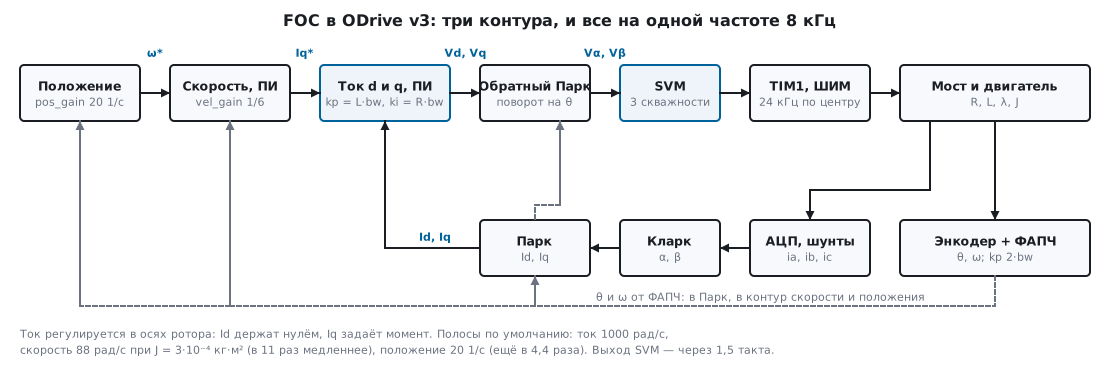
The chain is the same as in 57а.7. Phase currents → Clarke (α, β) → Park by the rotor angle θ (d, q) → two PI controllers give the voltages Vd, Vq → inverse Park (Vα, Vβ) → the modulator splits the vector into three duty cycles. Outside it is the speed loop, which sets Iq, and the position loop, which sets the speed.
The projects write Clarke differently. SimpleFOC (CurrentSense::getABCurrents)
uses β = (ia + 2·ib)/√3, as in 57а; ODrive (foc.cpp) uses β = (ib − ic)/√3.
With ia + ib + ic = 0 this is the same thing: on a circle in 1° steps the discrepancy together
with Park is no more than 7.2·10⁻¹⁶. If all three currents are measured, SimpleFOC first
subtracts a third of their sum from each — the sensor error is split evenly.
The projects are organised differently. In SimpleFOC loopFOC() reads the sensor, computes
the electrical angle, gets Uq and Ud according to the torque mode and calls
setPhaseVoltage(); move() runs the outer loops (speed, angle) and can be
called less often (motion_downsample). Both are called from loop(): the rate is
whatever the processor manages. In ODrive everything sits in the interrupt: current measurement,
angle estimation, loops, SVM — strictly once per 8 kHz cycle (57д.3).
Sine and cosine for Park come from a table. In SimpleFOC _sin is 65 values
of a quarter wave in 16-bit integers with linear interpolation on an 8-bit
fraction; over 3217 points in [0, 2π) the RMS error is 5.74·10⁻⁵ (the code comment
says 0.00006480), the largest over 10⁶ points is 1.59·10⁻⁴. ODrive uses
arm_sin_f32/arm_cos_f32 from CMSIS: a table of 512 segments, error no
more than 1.9·10⁻⁵. On the G474 the same is computed by CORDIC (section 46а).
57д.2 SVM versus sine: where the 15.47 % comes from
Each bridge phase is a half-bridge: the output voltage is from 0 to Vbus. A star-connected
motor only feels the differences between phases; it does not see an offset common to all three
phases. Sine PWM gives each phase 0.5 + m·sin(...) — the amplitude of the
phase voltage is no more than Vbus/2. But the line voltage is the difference
of two such sines, and its amplitude is √3 times the phase amplitude; if you add to
all three phases the same offset that "pushes" the vector towards the edges,
the limit of the phase amplitude becomes Vbus/√3 (line voltage — the bus itself). The ratio:
(Vbus/√3) / (Vbus/2) = 2/√3 = 1.154701 — 15.47 % more.
That is SVM. In SimpleFOC it is written as a "midpoint" shift
(BLDCMotor.cpp, SpaceVectorPWM mode): half the sum of the largest and the smallest
is subtracted from the three phase voltages.
          float Umin = min(Ua, min(Ub, Uc));
          float Umax = max(Ua, max(Ub, Uc));
          center -= (Umax+Umin) / 2;
ODrive (utils.cpp, the SVM function) does the same through six sectors:
it finds the sector of the vector, the times of the two adjacent basic vectors and three switching
moments. Sector 1:
            float t1 = alpha - one_by_sqrt3 * beta;
            float t2 = two_by_sqrt3 * beta;

            // PWM timings
            tA = (1.0f - t1 - t2) * 0.5f;
The input is a vector in units of "modulation", where 1 = ⅔·Vbus (mod_to_V = (2.0f / 3.0f)
* vbus_voltage in foc.cpp). The output is the switch-on moment of a phase as a fraction of the
half-period: the phase duty cycle is 1 − t. The real SVM, SimpleFOC and an
independent Python calculation give the same result:
| α, β | tA | tB | tC | valid |
|---|---|---|---|---|
| 0.5; 0 | 0.250000 | 0.750000 | 0.750000 | yes |
| 0; 0.5 | 0.500000 | 0.211325 | 0.788675 | yes |
| 0.3; 0.4 | 0.234530 | 0.303590 | 0.765470 | yes |
| −0.6; −0.2 | 0.857735 | 0.373205 | 0.142265 | yes |
| 0.75; 0.4330127 | 0.000000 | 0.500000 | 1.000000 | yes |
| 1; 0 | 0.000000 | 1.000000 | 1.000000 | yes |
| 0.8; 0.4618802 | −0.033333 | 0.500000 | 1.033333 | no |
SimpleFOC with its table sine differs from SVM in the fifth decimal place —
its inputs are Uq and an angle, not α, β.
The limit was checked by brute force: over 3600 directions the largest allowed magnitude
for SVM ranges from 0.866025 (√3/2, between basic vectors) to 1.000000
(along them). A circle of radius √3/2 in modulation units is 0.577350·Vbus of phase
amplitude. SimpleFOC at 24 V: sine mode holds Uq up to 12.0000 V
(0.5·Vbus), SVPWM up to 13.8564 V (0.577350·Vbus).
ODrive does not use the whole circle: mod_scalefactor = 0.80f * sqrt3_by_2 * ... —
no more than 0.692820 modulation, that is 0.461880·Vbus, less than even the
sine PWM limit. In return the duty cycle of any phase is no higher than 0.9: the low-side
switch is on for at least 10 % of the period — a window for the low-side shunt (57б.5).
57д.3 ODrive timing: PWM at 24 kHz, controller at 8 kHz
The numbers come from Board/v3/Inc/main.h: TIM_1_8_CLOCK_HZ = 168000000,
TIM_1_8_PERIOD_CLOCKS = 3500, TIM_1_8_RCR = 2, TIM_1_8_DEADTIME_CLOCKS
= 20. TIM1 and TIM8 count center-aligned (TIM_COUNTERMODE_CENTERALIGNED3 in
tim.c), the PWM period is 2·3500 clocks: 24000 Hz. The repetition counter of 2
gives an update event once every three half-periods, and the controller runs on every
second of them: CURRENT_MEAS_HZ = 168 MHz / (2·3500·3) = 8000 Hz, a cycle of
125 µs. The dead time of 20 clocks is 119 ns.
On the event where the counter is counting up, the ADC has just sampled the current in the "zero" vector, where the low-side switches are on (57б.2); on the opposite event it takes a sample at zero current for offset calibration. So one timer does both the PWM and the sampling at the right moment, as in 57б.3.
The output is computed ahead of time. In board.cpp the output timestamp is
timestamp + 3 * TIM_1_8_PERIOD_CLOCKS * (TIM_1_8_RCR + 1): 31500 clocks =
187.5 µs = 1.5 controller cycles — the middle of the interval when the new
duty cycles will be in effect. foc.cpp advances the inverse Park angle by
phase_vel × this time. The model does the same: the current is sampled at tₖ,
the duty cycles computed from it act from tₖ₊₁ to tₖ₊₂.
57д.4 Current loop: PI with pole cancellation
A winding along the d or q axis is R and L in series: a first-order plant with a
pole at R/L. ODrive sets the PI so that the controller zero cancels this
pole (motor.cpp, update_current_controller_gains):
    float p_gain = config_.current_control_bandwidth * config_.phase_inductance;
    float plant_pole = config_.phase_resistance / config_.phase_inductance;
    current_control_.pi_gains_ = {p_gain, plant_pole * p_gain};
The closed loop is again a first-order system with time constant 1/bw. By
default current_control_bandwidth = 1000 rad/s; for our motor
p_gain = 0.02 V/A, i_gain = 50 V/(A·s).
A step of Iq from 0 to 10 A, the real FieldOrientedController:
- for the first two cycles the current does not change — this is the 1.5-cycle delay from 57д.3;
- 63.2 % is reached in 1.000 ms, exactly 1/bw; 90 % in 2.125 ms;
- |Id| is no more than 0.0268 A: the axes are decoupled;
- the Iq peak within 10 ms is 9.6004 A, not 10.
The missing 0.4 A is back-EMF. The rotor accelerates (1.4215 rev/s after
10 ms), the EMF grows linearly, and a PI controller has zero error only against a constant
disturbance. Calculation: acceleration 1021.0 rad/s², EMF slope 20.85 V/s, lag
= slope / i_gain = 0.417 A. The cure is feedforward: bEMF_FF_enable
and R_wL_FF_enable in motor.hpp (off by default) add the calculated EMF and drops
to Vq and Vd.
The bandwidth cannot be raised indefinitely: the 1.5-cycle delay eats the stability margin. The same step at bw = 5000 rad/s gives a peak of 13.837 A (38.4 % overshoot), at 10000 rad/s the loop oscillates — a peak of 69.764 A within 10 ms.
SimpleFOC selects the torque mode with the torque_controller field. In
voltage mode the current is not measured at all: voltage.q = current_sp, that is, the
setpoint is Uq in volts directly. For high-resistance motors this is convenient (in ODrive
this type is called exactly that — MOTOR_TYPE_GIMBAL, and the "current" there is in volts). For
our 0.05 Ω motor it is dangerous: Uq = 0.5 V
on a stalled rotor gives an Iq peak of 9.488 A (Uq/R = 10 A), then the current falls
as the EMF rises; after 1 s with a 0.01 N·m load — 3.7662 rev/s, Iq 0.3264 A,
and Id 0.1313 A that nobody controls. The foc_current mode is a full
pair of PI controllers on d and q with a filter: by default DEF_PID_CURR_P 3, DEF_PID_CURR_I
300, DEF_CURR_BANDWIDTH 300 (defaults.h, the STM32 branch); the PI in
pid.cpp uses trapezoidal integration (Tustin) with output limiting.
57д.5 Speed, position and the angle sensor
The outer loop must be noticeably slower than the inner one — then the current loop
is "instantaneous" for it. ODrive defaults (controller.hpp):
pos_gain = 20 (rev/s)/rev, vel_gain = 1/6 N·m/(rev/s),
vel_integrator_gain = 2/6 N·m/(rev/s·s). The speed loop bandwidth is
vel_gain / (2π·J) = 88.42 rad/s for our J: 11.31 times lower than the
current loop, and the position loop (20 1/s) is another 4.42 times lower.
The torque constant is 8.27/Kv (motor.hpp); 8.27 = 60·√3/(4π), and at
Kv = 270 this is 0.03063 N·m/A.
Acceleration 0 → 20 rev/s in 0.2 s with these gains and the real current loop: the average Iq during acceleration is 6.2708 A (the J·a/Kt estimate is 6.1540 A), the speed error is no more than 1.1016 rev/s, after 0.4 s — 20.2759 rev/s, the overshoot of 0.276 rev/s is slowly removed by the integrator. Modulation is no higher than 0.1736 against a limit of 0.6928, duty cycles 0.4…0.6: the EMF at 20 rev/s is only 2.566 V.
The sensor. ODrive gets angle and speed from a PLL (encoder.cpp): prediction
from the speed, the error "encoder count − estimate", correction with pll_kp = 2·bw
and pll_ki = 0.25·kp² — two coincident poles, no oscillation. With
bandwidth = 1000 rad/s and 8 kHz kp·T = 0.250 (the code checks < 1).
Why: an 8192-count encoder at 3 rev/s gives 3.072 counts per cycle, and
"count difference per cycle" jumps between 2.9297 and 3.9062 rev/s; the PLL on
the same counts gives 2.9907…3.0060 rev/s. ODrive forces speeds below 0.5·T·ki = 62.5
counts/s to zero so that a stationary shaft does not jitter. Hall sensors go
through the same PLL with their own model (hall_model); without a sensor there is a flux
observer in sensorless_estimator.cpp and one more PLL with the same formula.
SimpleFOC makes the sensor a class: a descendant of Sensor implements a single
getSensorAngle() (0…2π), and the base class itself computes revolutions, full angle and speed
in update()/getVelocity(); the speed is a difference, taken no more often than once per
min_elapsed_time = 100 µs, followed by the DEF_VEL_FILTER_Tf = 5 ms filter.
Before _sin the angle is brought into [0, 2π) by _normalizeAngle: −0.5 → 5.783185,
7.0 → 0.716815.
57д.6 Motor parameters: how ODrive measures R and L
The current loop gains are computed from R and L, and ODrive measures them itself during
calibration with the rotor standing still. The laws are in motor.cpp and run verbatim
in the model.
Resistance. A voltage is applied along the α axis, and an integrator adjusts it
to reach the current calibration_current = 10 A: test_voltage_ += (kI *
current_meas_period) * (target_current_ - actual_current_), kI = 1 (V/s)/A.
It lasts 3000 cycles of 1 ms, the voltage is no higher than resistance_calib_max_voltage
= 2 V. The result is test_voltage_ / target_current_. In the model the current after 50 ms is
6.335 A, after 0.5 s — 9.9996 A; the measured value is 0.049999 Ω against 0.05
(−0.0012 %). Iβ is filtered at the same time: more than 0.2 of the current is an
ERROR_UNBALANCED_PHASES error (a broken or poorly connected phase).
Inductance. A ±2 V voltage changes sign every cycle; over 1250 ms
the sum of current increments is accumulated, L = |V| / (ΔI/dt). The current swing in the model is
12.3993 A, the measured value is 20.1658 µH against 20 (+0.829 %). The error comes from R, which
the method ignores: for a square wave with switching period T the correction
x/th(x) − 1 at x = T·R/(2L) gives 0.812 %. An acceptable result is from 2 to
4000 µH, otherwise it is an error.
57д.7 Pitfalls
The current during acceleration is lower than the setpoint, although the controller "has an integral".
The EMF grows linearly, and the PI leaves an error of slope/i_gain: 0.417 A at an
acceleration of 1021 rad/s². Enable EMF feedforward or raise the bandwidth.
Raised the current bandwidth — the motor squealed and went into an error. The 1.5-cycle delay: at bw = 5000 rad/s the overshoot is 38.4 %, at 10000 rad/s the loop is unstable. At 8 kHz a reasonable limit is a few thousand rad/s.
Not enough speed at full throttle. Sine PWM gives 0.5·Vbus
of phase amplitude, SVM gives 0.577·Vbus. In SimpleFOC the default is
foc_modulation = FOCModulationType::SinePWM — you enable SVM yourself. ODrive also cuts modulation to
0.8 of the circle (0.462·Vbus); in saturation the current integrators decay
by a factor of 0.99 per cycle.
SimpleFOC in voltage mode burns MOSFETs. The setpoint is in volts, and nobody limits the
current: 0.5 V across 0.05 Ω is almost 10 A at start.
For low-resistance motors use foc_current and a current sensor.
_sin got a negative angle. The table index is computed by a cast
to unsigned int; on Cortex-M4 that is the VCVT.U32.F32 instruction. SimpleFOC itself
normalizes the angle with _normalizeAngle in electricalAngle(); your own code must do
the same.
Encoder speed looks like a "saw". The count difference per cycle at 8 kHz is quantized in steps of 0.977 rev/s with 8192 counts. You need a PLL or a filter.
R calibration fails. 10 A cannot be reached with a 2 V limit if
R > 0.2 Ω — raise resistance_calib_max_voltage or lower the current.
57д.8 Summary
- FOC: Clarke, Park, two PI controllers on d and q, inverse Park, modulator; SimpleFOC and ODrive write Clarke differently, the results agree to within 7.2·10⁻¹⁶.
- SVM gives a phase up to Vbus/√3 versus Vbus/2 for sine — 2/√3 = 1.1547 times
more; the real ODrive
SVMand the SimpleFOC "midpoint" shift agree; ODrive uses 0.8 of the circle, duty cycle no higher than 0.9. - ODrive v3: center-aligned PWM at 24 kHz, controller at 8 kHz (cycle 125 µs), output computed 1.5 cycles ahead (187.5 µs).
- Current loop:
kp = L·bw,ki = R·bw; at 1000 rad/s 63.2 % in 1.000 ms; 5000 rad/s gives 38.4 % overshoot; without EMF feedforward the current lags. - Speed loop 88 rad/s (11.3 times slower than current), position loop 20 1/s; the PLL smooths speed to 2.99…3.01 rev/s versus 2.93…3.91 for the count difference.
- ODrive calibration: R with an integrator at 10 A (−0.0012 %), L with an alternating 2 V (+0.829 % because of R).
- On Cortex-M4F (armclang -O2):
get_alpha_beta_outputis 760 bytes,SVMis 468 bytes with no calls, SimpleFOC_sinis 248 bytes.
Next: section 57е "Stepper motor winding current: the PWM chopper and decay modes" — from the brushless motor back to the stepper: how the driver holds the current in the winding, slow, fast and mixed decay.