 Embedded HandbookApps
57е. Stepper motor winding current: the PWM chopper and decay modes
In 57а.3 microstepping came down to a table: at each step winding A needs the current
cos, winding B needs sin. But the table tells you what current is needed, not how
to get it. A winding is an inductance with a resistance (57.5), and while the motor
turns, a back-EMF is also induced in it. The driver holds the current like this: it turns
the bridge on, waits until the current rises to the threshold, turns it off for an off-time, turns it on again.
That is the chopper. The most interesting part is what to do with the current during the off-time: let it
decay slowly through the shorted winding, dump it quickly with a reverse voltage,
or mix one with the other.
In this section: the three bridge states and two ways to hold the current (constant off-time and constant frequency); why slow decay cannot hold small currents and why it spoils the sine while the motor turns; your own chopper on TIM1/TIM8 with an external comparator, a DAC for the threshold and an ADC for decay tuning; what of all this you can see in ready-made drivers.
References: RM0090 Rev 19 (TIM1/TIM8 on the F4: clearing OCxREF by ETR — 17.3.13,
the TIMx_SMCR register with reset mode and the ETF filter, the OCxM modes;
ADC — triggering the injected group, table 69, ADC_JSQR), RM0008 Rev 17
(F1: JEXTSEL, the ADC2_ETRGINJ_REMAP bit, the ETF filter), DS8626 Rev 9
(F407 pins), DocID14611 Rev 12 and DocID13587 Rev 17 (pins and contents of the
F103xE and F103x8/xB), RM0440 Rev 6 (G4: the ETR source is a comparator). The winding
model is our own; its parameters are an example, not the datasheet of a particular motor:
R = 1.5 Ω, L = 3 mH, a 24 V bus, phase back-EMF amplitude 0.25 V per
rad/s of the shaft, 50 electrical revolutions per mechanical one (1.8° per step),
full current 1.5 A. The run is _verify/chop57e/sim57e.c, independently —
ref57e.py, the record is chop57e_host.txt. For the TMC drivers — the sources of
Klipper (github.com/Klipper3d/klipper, commit 7bc4d09), license
GPL-3.0 (file COPYING, © Kevin O'Connor).
Terms used in the documentation
Term Meaning chopper, PWM current regulation holding the current by switching the transistors fixed (constant) off-time the off-time has a fixed length fixed frequency, peak current mode a fixed period, regulation by the current peak slow / fast / mixed decay ways to let the current fall during the off-time blanking time the comparator is ignored for a while after turn-on recirculation, synchronous rectification current flow during the off-time; conducting transistors instead of diodes sense resistor current-measuring shunt back-EMF voltage induced in the winding by the rotating rotor reset mode ( SMS = 100),ETRFcounter reset mode, the filtered ETR input OCxREFclear,OCxCEthe ETR input forces the channel inactive TOFF,TBL,HSTRT,HEND(TMC)off-time, blanking, hysteresis start and end spreadCycle, stealthChop chopper modes of TMC drivers
57е.1 The three bridge states and two ways to hold the current
The winding sits in an H-bridge: leg 1 and leg 2, each with a high-side and a low-side switch. Let the current flow from leg 1 to leg 2. Then the bridge has three useful states:
| State | Switches | Voltage across the winding | Current through the ground shunt |
|---|---|---|---|
| drive | top of leg 1, bottom of leg 2 | +24 V | the whole winding current |
| slow decay | both bottoms | 0 (short) | zero: the current circulates through the two low-side switches |
| fast decay | bottom of leg 1, top of leg 2 | −24 V | the winding current, but with the opposite sign |
The comparator compares the shunt voltage with a threshold: once it is exceeded, drive is turned off. Model numbers at a current of 1.5 A:
- drive: the current rises at 7.250 A/ms (
(24 − 1.5·1.5)/3 mH); - slow decay over 20 µs: a drop of 14.93 mA — the winding decays with the time constant L/R = 2000 µs;
- fast decay over 20 µs: 174.13 mA, 11.7 times more;
- mixed (5 µs fast, 15 µs slow): 54.58 mA.
How long to hold the off-time is decided in different ways. Constant off-time: after the comparator trips, the bridge stays in decay for exactly 20 µs, then drives again; the frequency "floats". Constant frequency: every 50 µs (20 kHz) drive starts anew, and a trip only cuts it short until the end of the period.
After turn-on there is a spike on the shunt from recharging the switch capacitances, so the comparator is ignored for a while at first — this is blanking. In our chopper its role is played by the timer's ETR input filter: 8 equal samples every 32 cycles at 168 MHz — 1.524 µs (57е.5). While blanking lasts, the current rises another 11.05 mA above the threshold.
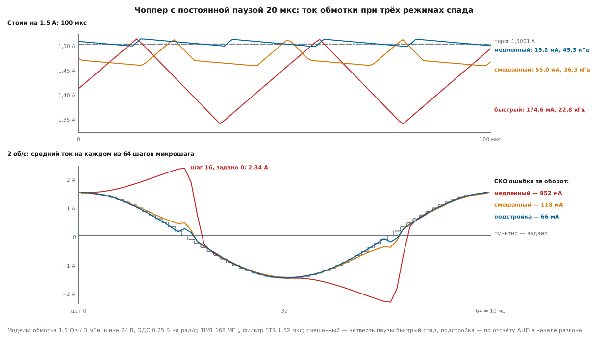
57е.2 Standing still: ripple, frequency and average current
The motor stands still, the winding is at step 0 of the table (full current, DAC threshold 1862 — 1.5001 A) or at step 15 (code 25 of 255 — 0.1474 A). A chopper with a constant off-time of 20 µs and one with a constant frequency of 20 kHz:
| Mode | 1.5 A: average | error | peak-to-peak | frequency | 0.147 A: average | error | peak-to-peak |
|---|---|---|---|---|---|---|---|
| off-time, slow | 1.5030 A | +2.84 mA | 15.17 mA | 45.30 kHz | 1.1327 A | +985.28 mA | 11.33 mA |
| off-time, mixed ¼ | 1.4722 A | −27.99 mA | 55.00 mA | 36.32 kHz | 0.1263 A | −21.15 mA | 41.51 mA |
| off-time, fast | 1.4228 A | −77.39 mA | 174.55 mA | 22.78 kHz | 0.0780 A | −69.48 mA | 160.77 mA |
| off-time, ADC tuning | 1.4941 A | −6.09 mA | 25.13 mA | 42.66 kHz | 0.1366 A | −10.86 mA | 26.53 mA |
| 20 kHz, slow | 1.4933 A | −6.81 mA | 34.01 mA | 20.00 kHz | 0.4724 A | +324.94 mA | 11.62 mA |
| 20 kHz, fast | 1.3127 A | −187.49 mA | 380.06 mA | 20.00 kHz | 0.0588 A | −88.68 mA | 205.02 mA |
What you can see.
- The chopper holds the peak, not the average. The average current is below the threshold by about half the peak-to-peak ripple: with fast decay −77.39 mA at a ripple of 174.55 mA. Slow decay is even slightly above the threshold (+2.84 mA): the overshoot during blanking (11 mA) is larger than half of its small sawtooth.
- The faster the decay, the less often the switching: 45.30 → 36.32 → 22.78 kHz. With a constant off-time the frequency depends on the current and the speed — when turning at 2 rev/s with fast decay the cycles in the model run from 10.36 to 46.46 kHz, and the lower bound is already audible. Constant frequency is free of this, but with fast decay it has nothing to limit the decay length with: a ripple of 380.06 mA.
- Fast decay at a small current overshoots zero: at 0.147 A the current goes down to −2.8 mA during the off-time, at 20 kHz down to −47.3 mA.
- Slow decay does not hold a small current at all: 0.147 A is commanded, but 1.1327 A flows. This is not a bug in the model — see the next subsection.
57е.3 The "floor" of slow decay
Blanking is the minimum drive time: even if the current is already above the threshold,
the comparator trips no earlier than after 1.524 µs. So the bridge cannot
give a duty cycle below t / (t + t_off). The average current with slow decay
does not go below
I_floor = V_bus · t / (R · (t + t_off)) — at 24 V, 1.5 Ω, t = 1.524 µs:
| Off-time | Model | Formula |
|---|---|---|
| 20 µs | 1.1327 A | 1.1327 A |
| 40 µs | 0.5872 A | 0.5872 A |
| 80 µs | 0.2991 A | 0.2991 A |
The inductance does not enter the formula. With an off-time of 20 µs slow decay holds table steps 0…7 (the last one — 1.1585 A commanded, 1.1633 A in the model), while from step 8 (1.0586 A) and below the current sits at 1.1327 A. That is why pure slow decay is used only with a high-voltage bus and a large current — or the off-time is made longer (the frequency drops into the audible range), or fast decay is added. Mixed ¼ at 0.147 A is off by −21.15 mA, tuning by −10.86 mA.
57е.4 Rotation: back-EMF spoils the sine
The rotor turns evenly together with the field, with no load; the back-EMF of phase A
is −E·sin θ, E = 0.785 V at 0.5 rev/s, 1.571 V at 1, 3.142 V at 2 and
6.283 V at 4 rev/s. Microstepping 1/16: 64 steps per electrical revolution, 50
of them per mechanical one. We measure the average current at each step against
the commanded one, and the RMS error over a revolution:
| Mode | 0.5 rev/s | 1 rev/s | 2 rev/s | 4 rev/s | Peak-to-peak at 2 rev/s |
|---|---|---|---|---|---|
| off-time, slow | 555.9 mA | 723.7 mA | 952.3 mA | 1297.7 mA | 21.7 mA |
| off-time, fast | 82.8 mA | 81.0 mA | 84.7 mA | 129.4 mA | 181.1 mA |
| off-time, mixed ¼ | 40.6 mA | 46.5 mA | 117.6 mA | 524.4 mA | 60.7 mA |
| off-time, tuning | 35.0 mA | 39.5 mA | 65.6 mA | 122.5 mA | 61.9 mA |
| 20 kHz, slow | 285.6 mA | 464.6 mA | 726.1 mA | 1091.0 mA | 63.0 mA |
Why slow decay fails. In the first quarter of a revolution the commanded current
is positive and decreasing, while the back-EMF −E·sin θ is negative. In
slow decay the winding sees L·di/dt = −R·i − e = −R·i + E·sin θ: the EMF
pushes the current up. The shorted winding works as a generator, and the current grows
where it should fall: at step 16 (zero commanded) at 2 rev/s
2.342 A flows (see the figure). The fundamental of the current is 2.0780 A instead of 1.5 and
lags by 32.96°. In the second quarter, where the current rises, the EMF helps — there
slow decay is good.
Fast decay always dumps the current, but pays with a 181.1 mA sawtooth and an average below the command. Mixed ¼ is good up to 1 rev/s; at 4 rev/s a quarter of the off-time is not enough (524.4 mA). Tuning increases the fast part by itself when needed: on average 14.0 % of the off-time at 0.5 rev/s, 17.8 % at 1, 29.0 % at 2 and 65.1 % at 4 rev/s; the fundamental at 2 rev/s is 1.4776 A with a lag of 4.16°.
57е.5 A chopper on TIM1: the comparator resets the counter
An STM32 timer makes a constant off-time on its own. The comparator output goes to the
ETR input. In TIMx_SMCR reset mode is selected (SMS = 100: "a rising edge of TRGI
reinitializes the counter and updates the registers"), the source TS = 111 —
ETRF, the filter ETF = 1111 (fDTS/32, N = 8). Each trip
clears the counter, and channels 1 and 2 in PWM modes split the count into
the off-time and drive segments:
| Counter | The "to" leg (PWM 2, CCR = n_off) | The "from" leg (PWM 1, CCR = n_fast) | State |
|---|---|---|---|
CNT < n_fast |
bottom | top | fast decay |
n_fast ≤ CNT < n_off |
bottom | bottom | slow decay |
CNT ≥ n_off |
top | bottom | drive |
When counting up, PWM 1 is active while CNT < CCR, PWM 2 is the opposite;
the active level of a channel is the high-side switch of the leg, and the complementary output CHxN with
dead time is the low-side one. n_fast = 0 means pure slow decay,
n_fast = n_off pure fast decay. The current sign is changed by swapping
the channel modes. For the F407 with timers at 168 MHz n_off = 3360 (20 µs),
mixed ¼ is n_fast = 840. The code that computes the modes and CCR is shared
by the firmware and the model:
void chop_legs(chop_out_t *o, int8_t sign, uint16_t n_off, uint16_t n_fast)
{
    if (n_fast > n_off)
        n_fast = n_off;
    o->sign = sign;
    if (sign > 0) {                    /* ток из плеча 1 в плечо 2 */
        o->ocm1 = OCM_PWM2; o->ccr1 = n_off;
        o->ocm2 = OCM_PWM1; o->ccr2 = n_fast;
    } else if (sign < 0) {             /* ток из плеча 2 в плечо 1 */
        o->ocm1 = OCM_PWM1; o->ccr1 = n_fast;
        o->ocm2 = OCM_PWM2; o->ccr2 = n_off;
    } else {                           /* нулевой ток: оба нижних ключа, обмотка закорочена */
        o->ocm1 = OCM_FORCE_LOW; o->ccr1 = 0;
        o->ocm2 = OCM_FORCE_LOW; o->ccr2 = 0;
    }
}
The bridge of one winding and writing the result into the timer:
static void tim_apply(tim_t *t, const chop_out_t *o, int restart)
{
    t->CCR1  = o->ccr1;
    t->CCR2  = o->ccr2;
    t->CCMR1 = ((uint32_t)o->ocm1 << TIM_CCMR1_OC1M_Pos) | TIM_CCMR1_OC1PE
             | ((uint32_t)o->ocm2 << TIM_CCMR1_OC2M_Pos) | TIM_CCMR1_OC2PE;
    if (restart)
        t->EGR = TIM_EGR_UG;
}

/* Мост одной обмотки: счётчик вверх, сброс по фронту ETR, канал 4 — запуск АЦП. */
static void tim_bridge_init(tim_t *t)
{
    t->CR1   = 0;
    t->PSC   = 0;
    t->ARR   = 0xFFFFu;                   /* не сработал компаратор — пауза через 65536 тактов */
    t->SMCR  = (ETF_CODE << TIM_SMCR_ETF_Pos) | TIM_SMCR_TS_ETRF | TIM_SMCR_SMS_RESET;
    t->CCMR1 = (OCM_FORCE_LOW << TIM_CCMR1_OC1M_Pos) | (OCM_FORCE_LOW << TIM_CCMR1_OC2M_Pos);
    t->CCMR2 = (OCM_PWM2 << TIM_CCMR2_OC4M_Pos) | TIM_CCMR2_OC4PE;   /* OC4REF встаёт при CNT = CCR4 */
    t->CCR4  = N_OFF + N_ADC;
    t->CCER  = TIM_CCER_CC1E | TIM_CCER_CC1NE | TIM_CCER_CC2E | TIM_CCER_CC2NE
             | TIM_CCER_CC4E;                      /* канал 4 на вывод не выведен */
    t->BDTR  = N_DT | TIM_BDTR_MOE;
    t->EGR   = TIM_EGR_UG;
    t->CR1   = TIM_CR1_CEN;
}
Two subtleties from RM0090. First: PWM without CCR preload (OCxPE = 0)
is allowed by the document only in one-pulse mode — so OCxPE is
on, and new CCR values take effect at the next counter reset (which is also the update
event). Second: in PWM modes the OCxREF level changes only when
the comparison result changes. Switching from "forced inactive" to PWM
when the current sign changes will not turn the output on by itself — so tim_apply with
restart issues UG: the counter goes to zero, and a new off-time starts from the beginning. The model does
the same. ARR = 65535 is a fallback: if the comparator has not tripped within
390 µs, the counter overflows and starts the off-time by itself.
Constant frequency is done by another TIM1 feature — channel clearing
(OCxCE): a high level on ETRF holds OCxREF at zero until the next
update event; with CCR > ARR (100 % PWM) the channel turns on again at
overflow:
void tim_fixed_slow_init(tim_t *t)
{
    t->CR1   = 0;
    t->ARR   = TIM_HZ / 20000u - 1u;
    t->SMCR  = ETF_CODE << TIM_SMCR_ETF_Pos;      /* ETR только для гашения, режима сброса нет */
    t->CCR1  = TIM_HZ / 20000u;
    t->CCMR1 = (OCM_PWM1 << TIM_CCMR1_OC1M_Pos) | TIM_CCMR1_OC1PE | TIM_CCMR1_OC1CE
             | (OCM_FORCE_LOW << TIM_CCMR1_OC2M_Pos);
    t->CCER  = TIM_CCER_CC1E | TIM_CCER_CC1NE | TIM_CCER_CC2E | TIM_CCER_CC2NE;
    t->BDTR  = N_DT | TIM_BDTR_MOE;
    t->EGR   = TIM_EGR_UG;
    t->CR1   = TIM_CR1_CEN;
}
Only slow decay here: leg 2 stays on the low-side switch all the time. Mixed decay cannot be done this way — clearing holds until the end of the period, and there is nothing to measure "the first 5 µs" in it with.
Pins (winding A — TIM1, winding B — TIM8); according to DS8626 and DocID14611 they are the same on the F407 and the F103xE:
| Signal | TIM1 | TIM8 | F407, alternate function |
|---|---|---|---|
| CH1 / CH2 | PA8 / PA9 | PC6 / PC7 | AF1 / AF3 |
| CH1N / CH2N | PB13 / PB14 | PA7 / PB0 | AF1 / AF3 |
| ETR (comparator output) | PA12 | PA0 | AF1 / AF3 |
| shunt → ADC, threshold ← DAC | PA1 (ADC1_IN1), PA4 (DAC1) | PA2 (ADC2_IN2), PA5 (DAC2) | analog input |
On the F103 the timers run at 72 MHz: n_off = 1440, filter ETF = 1100 (fDTS/16,
N = 8 — 128 cycles, 1.78 µs), dead time 36 cycles. A second timer
with complementary outputs and a DAC exist only on the F103xE (high-density): on the
F103x8/xB, according to DocID13587, there is only one timer of this kind and no DAC — there you need
a different circuit for the threshold and for the second winding.
On the G4 no external comparator is needed: according to RM0440 the timer's ETR source is selected
by the ETRSEL field in TIMx_AF1, and tim_etr1 of TIM1 is the COMP1 output; the threshold comes from
the internal DAC, and blanking is done by the comparator itself from a timer channel (as in 57б.6 and
44.7). This variant is described but was not built.
57е.6 Steps, the DAC and decay tuning by the ADC
The table and the threshold live in the shared file chop57e.c. Step idx (0…63) gives the magnitude and
sign of the current in winding A; winding B is the same call with idx + 48. The field strength
√(A² + B²) over the 64 steps is from 0.998 to 1.002 of full, as in 57а.3.
int8_t ustep_level(uint8_t idx, uint8_t *level)
{
    idx &= 63u;
    uint8_t q = idx >> 4, r = idx & 15u;
    uint8_t v = (q == 0u || q == 2u) ? ustep_cos[r] : ustep_cos[16u - r];
    *level = v;
    if (v == 0u)
        return 0;
    return (q == 0u || q == 3u) ? 1 : -1;
}
void chop_set(chop_out_t *o, const chop_cfg_t *c, uint8_t idx)
{
    uint8_t level;
    int8_t sign = ustep_level(idx, &level);
    uint16_t n_fast = c->mode == DECAY_SLOW ? 0u : c->mode == DECAY_FAST ? c->n_off : c->n_fast;
    o->dac = (uint16_t)(((uint32_t)level * c->dac_full + 127u) / 255u);
    chop_legs(o, sign, c->n_off, n_fast);
}
The shunt amplifier gives 1 V per ampere (for example, 0.1 Ω and a gain of 10), the DAC and
the ADC run at 3.3 V — one scale, 0.806 mA per code; full current is code 1862. What
gets written into the timer with n_off = 3360, n_fast = 840:
| Step | Code of 255 | Sign | DAC | OC1M / CCR1 | OC2M / CCR2 |
|---|---|---|---|---|---|
| 0 | 255 | + | 1862 | 7 (PWM 2) / 3360 | 6 (PWM 1) / 840 |
| 8 | 180 | + | 1314 | 7 / 3360 | 6 / 840 |
| 15 | 25 | + | 183 | 7 / 3360 | 6 / 840 |
| 16 | 0 | 0 | 0 | 4 (inactive) / 0 | 4 / 0 |
| 17 | 25 | − | 183 | 6 / 840 | 7 / 3360 |
| 32 | 255 | − | 1862 | 6 / 840 | 7 / 3360 |
Tuning. Channel 4 (CCR4 = n_off + 168, 1 µs into drive)
triggers an injected conversion: ADC1 on TIM1_CH4
(JEXTSEL 0000), ADC2 on TIM8_CH4 (1110). At this moment the shunt sees
the current with which the winding came out of the off-time. If it is not below the threshold, the decay did not
keep up, and the fast part grows by 1/8 of the off-time; if it is below, the fast part shrinks by 1/32.
Eight trips in a row give 420, 840, … 3360 (all fast), then
3255, 3150, 3045.
uint16_t chop_adapt(uint16_t n_fast, uint16_t valley, uint16_t thr, uint16_t n_off)
{
    uint32_t up = n_off / 8u, down = n_off / 32u, n = n_fast;
    if (valley >= thr)
        n = n + up > n_off ? n_off : n + up;
    else
        n = n > down ? n - down : 0u;
    return (uint16_t)n;
}
The sample must finish before the ETR filter trips (1.33…1.52 µs after the start of drive, depending on the phase of the filter samples), otherwise the bridge goes into the off-time in the middle of the sample and the shunt shows zero. So the sampling time is the shortest: 3 ADC cycles at 21 MHz on the F407.
static void adc_init(void)
{
    RCC_APB2ENR |= RCC_ADC1EN | RCC_ADC2EN;
    ADC_CCR = 1u << 16;                                    /* ADCPRE = 01: 84 МГц / 4 = 21 МГц */
    ADC1->SMPR2 = 0;                       /* 3 такта АЦП: выборка кончится раньше, чем сработает фильтр ETR */
    ADC2->SMPR2 = 0;
    ADC1->JSQR = 1u << ADC_JSQR_JSQ4_Pos;                  /* JL = 0: один канал, PA1 */
    ADC2->JSQR = 2u << ADC_JSQR_JSQ4_Pos;                  /* PA2 */
    ADC1->CR1 = ADC_CR1_JEOCIE;
    ADC2->CR1 = ADC_CR1_JEOCIE;
    ADC1->CR2 = (1u << 20) | (0u << 16) | ADC_CR2_ADON;    /* по фронту, JEXTSEL 0000 — TIM1_CH4 */
    ADC2->CR2 = (1u << 20) | (14u << 16) | ADC_CR2_ADON;   /* по фронту, JEXTSEL 1110 — TIM8_CH4 */
}
With JL = 0 one channel is converted, and it is taken from JSQ4, not from
JSQ1 — that is how RM0090 and RM0008 put it. On the F103 the same is done via JEXTTRIG/JEXTSEL
in bits 15:12: ADC1 — 001 (TIM1_CC4), ADC2 — 110 plus the
ADC2_ETRGINJ_REMAP bit in AFIO_MAPR, otherwise 110 means EXTI15; and before
use, the CAL calibration.
The step, the ADC interrupt and startup:
void stepper_step(int8_t dir)
{
    int8_t s0 = out[0].sign, s1 = out[1].sign;
    step_idx = (uint8_t)((step_idx + dir) & 63u);
    chop_set(&out[0], &cfg[0], step_idx);
    chop_set(&out[1], &cfg[1], (uint8_t)(step_idx + 48u));
    DAC->DHR12R1 = out[0].dac;
    DAC->DHR12R2 = out[1].dac;
    tim_apply(TIM1, &out[0], out[0].sign != s0);
    tim_apply(TIM8, &out[1], out[1].sign != s1);
}

static void adapt(unsigned w, tim_t *t, uint16_t valley)
{
    chop_out_t *o = &out[w];
    if (cfg[w].mode != DECAY_AUTO || o->sign == 0)
        return;
    cfg[w].n_fast = chop_adapt(cfg[w].n_fast, valley, o->dac, cfg[w].n_off);
    chop_legs(o, o->sign, cfg[w].n_off, cfg[w].n_fast);
    tim_apply(t, o, 0);
}
#if defined(CHIP_F407)
void ADC_IRQHandler(void)
#else
void ADC1_2_IRQHandler(void)
#endif
{
    if (ADC1->SR & ADC_SR_JEOC) {
        ADC1->SR = ~ADC_SR_JEOC;
        adapt(0, TIM1, (uint16_t)ADC1->JDR1);
    }
    if (ADC2->SR & ADC_SR_JEOC) {
        ADC2->SR = ~ADC_SR_JEOC;
        adapt(1, TIM8, (uint16_t)ADC2->JDR1);
    }
}

void chopper_init(void)
{
    pins_init();
    RCC_APB1ENR |= RCC_DACEN;
    RCC_APB2ENR |= RCC_TIM1EN | RCC_TIM8EN;
    DAC->CR = DAC_CR_EN1 | DAC_CR_EN2;
    adc_init();
    step_idx = 0;
    stepper_step(0);                                       /* шаг 0: A — полный ток, B — ноль */
    tim_bridge_init(TIM1);
    tim_bridge_init(TIM8);
    tim_apply(TIM1, &out[0], 1);
    tim_apply(TIM8, &out[1], 1);
    NVIC_ISER0 = 1u << ADC_IRQ_NUM;
}
The ADC interrupt number is 18 on both (ADC_IRQn on the F407, ADC1_2_IRQn on the F103). It fires on every chopper
cycle — standing still at 1.5 A that is 45.3 thousand times a second per winding; how much this
costs the processor was not measured.
Everything is built with arm-none-eabi-gcc 12.2.1 with -Os -Wall -Wextra -Werror:
fw57e.c is 928 bytes of code for the F407 (Cortex-M4) and 940 for the F103
(Cortex-M3), chop57e.c is 241 bytes on both; of these chopper_init takes 544/556,
stepper_step 124, adapt 100, the ADC handler 76.
Ready-made drivers. In chips such as the A4988 and DRV8825 the same parts —
a comparator with a threshold from the reference voltage input, the off-time, blanking and the choice of
decay — are built in; the pins and the current formulas are taken from the datasheet of the particular
chip, and this section was not checked against them. On the TMC2208/TMC2209 these are fields of the
CHOPCONF register; their layout and defaults can be seen in Klipper (tmc2208.py,
tmc2209.py): toff — bits 3:0, hstrt 6:4, hend 10:7, tbl 16:15,
vsense — bit 17; Klipper writes toff = 3, hstrt = 5, hend = 0,
tbl = 2 (on the TMC2130 — 4, 0, 7, 1). The off-time and blanking are the same two quantities
as in our model; the Trinamic datasheet converts them into microseconds.
Klipper computes the current in tmc2130.py like this: I = (CS + 1)·Vfs / (32·(Rsh +
0.020)·√2) (RMS value), Vfs = 0.32 V, or 0.18 V at
vsense = 1; the default shunt is 0.110 Ω. For 0.8 A this gives vsense = 1,
IRUN = 25 and 0.7955 A; for 1.2 A the sensitive scale is not enough
(its limit is 0.9791 A), so the result is vsense = 0, IRUN = 21, 1.1966 A. By
default Klipper uses spreadCycle mode; stealthChop is enabled with
stealthchop_threshold. The Klipper documentation says that spreadCycle gives
more torque and accuracy, while stealthChop is noticeably quieter, but in tests it lagged
in position by about 75 % of a full step.
57е.7 Pitfalls
A small current is not held — the motor heats up while holding. The "floor"
of slow decay: V_bus·t/(R·(t + t_off)). At 24 V, 1.5 Ω, blanking of
1.524 µs and an off-time of 20 µs — 1.1327 A instead of the commanded 0.147 A. You need
mixed decay or a longer off-time.
When accelerating, the motor loses torque and is noisy, although it is fine standing still. Slow decay in the decreasing quarter does not dump the current against the back-EMF: at 2 rev/s the current is 2.342 A where zero is commanded, RMS error 952.3 mA. Use mixed or tuned decay.
Constant frequency plus fast decay on conducting switches — a current without limit. The current crossed zero during the off-time, the shunt sees it as drive current, the comparator keeps clearing — and the bridge drives the current in the opposite direction. In the model at 0.5 rev/s up to 15.986 A, at 2 rev/s up to 13.627 A. You need a zero detector or decay through diodes, and above all a fault input (57а.6).
Tuning does not work — the ADC shows zero. The sample is longer than the time until the ETR filter trips: the bridge went into the off-time in the middle of the sample. The trigger comes 1 µs in, the earliest trip is at 1.33 µs: less than a third of a microsecond is left for the sample.
The current sign changed — the winding stays silent for up to 390 µs. The channel was switched from
"forced inactive" to PWM without UG: the OCxREF level waits for the comparison
result to change, that is, for a counter overflow.
The second winding "trips" on its own. ADC2 on the F103 with JEXTSEL
= 110 without ADC2_ETRGINJ_REMAP is triggered by EXTI15, not by TIM8.
The chopper whines. Constant off-time means variable frequency: when turning with fast decay, down to 10.36 kHz in the model. Either a constant frequency, or a shorter off-time.
57е.8 Summary
- The bridge holds the current with three states: drive (+24 V), slow decay (short, 14.93 mA in 20 µs at 1.5 A), fast decay (−24 V, 174.13 mA).
- The chopper holds the peak: the average current is below the threshold by half the sawtooth (−77.39 mA with fast decay), with slow decay it is +2.84 mA.
- Blanking sets a "floor" for slow decay:
V_bus·t/(R·(t + t_off))= 1.1327 A with a 20 µs off-time; 0.5872 A with 40 µs. - While the motor turns, slow decay loses to the back-EMF: RMS error from 555.9 mA at 0.5 rev/s to 1297.7 mA at 4 rev/s; mixed ¼ — 40.6…524.4 mA; tuning by the ADC — 35.0…122.5 mA, with the fast-decay share from 14.0 % to 65.1 %.
- A constant off-time is made by TIM1 in reset mode on ETR (
SMS= 100,TS= 111,ETF= 1111 — 1.524 µs at 168 MHz), a constant frequency by channel clearingOCxCE; on a sign change —UG. - Firmware for two windings on TIM1/TIM8 + DAC + ADC1/ADC2: 928 bytes for the F407 and 940 for the F103xE plus 241 bytes of shared logic.
Full sources
chop57e.c — the chopper logic: the microstep table, bridge modes, the DAC threshold, decay tuning.
/* Раздел 57е: логика чоппера — таблица микрошага, режимы каналов моста, порог ЦАП, подстройка спада. */
#include "chop57e.h"

/* Четверть косинуса для микрошага 1/16: 255·cos(k·π/32), k = 0…16 — та же таблица, что в 57а.3. */
const uint8_t ustep_cos[17] = {
    255, 254, 250, 244, 236, 225, 212, 197, 180, 162, 142, 120, 98, 74, 50, 25, 0
};

/* Ток обмотки A на шаге idx (0…63 — электрический оборот): модуль 0…255 и знак.
 * Обмотка B — тот же вызов с idx + 48 (синус = косинус, сдвинутый на четверть оборота). */
int8_t ustep_level(uint8_t idx, uint8_t *level)
{
    idx &= 63u;
    uint8_t q = idx >> 4, r = idx & 15u;
    uint8_t v = (q == 0u || q == 2u) ? ustep_cos[r] : ustep_cos[16u - r];
    *level = v;
    if (v == 0u)
        return 0;
    return (q == 0u || q == 3u) ? 1 : -1;
}

/* Плечи моста по знаку тока. Счётчик сбрасывается в 0 срабатыванием компаратора:
 *   CNT < n_fast           — быстрый спад: плечо «от» на верхнем ключе, плечо «к» на нижнем (−Vпит);
 *   n_fast <= CNT < n_off  — медленный спад: оба нижних ключа (обмотка закорочена);
 *   CNT >= n_off           — разгон: плечо «к» на верхнем ключе, плечо «от» на нижнем (+Vпит).
 * ШИМ 2 активен при CNT >= CCR, ШИМ 1 — при CNT < CCR; активный выход = верхний ключ плеча. */
void chop_legs(chop_out_t *o, int8_t sign, uint16_t n_off, uint16_t n_fast)
{
    if (n_fast > n_off)
        n_fast = n_off;
    o->sign = sign;
    if (sign > 0) {                    /* ток из плеча 1 в плечо 2 */
        o->ocm1 = OCM_PWM2; o->ccr1 = n_off;
        o->ocm2 = OCM_PWM1; o->ccr2 = n_fast;
    } else if (sign < 0) {             /* ток из плеча 2 в плечо 1 */
        o->ocm1 = OCM_PWM1; o->ccr1 = n_fast;
        o->ocm2 = OCM_PWM2; o->ccr2 = n_off;
    } else {                           /* нулевой ток: оба нижних ключа, обмотка закорочена */
        o->ocm1 = OCM_FORCE_LOW; o->ccr1 = 0;
        o->ocm2 = OCM_FORCE_LOW; o->ccr2 = 0;
    }
}

/* Всё для шага idx: порог ЦАП по таблице и режимы каналов по знаку. */
void chop_set(chop_out_t *o, const chop_cfg_t *c, uint8_t idx)
{
    uint8_t level;
    int8_t sign = ustep_level(idx, &level);
    uint16_t n_fast = c->mode == DECAY_SLOW ? 0u : c->mode == DECAY_FAST ? c->n_off : c->n_fast;
    o->dac = (uint16_t)(((uint32_t)level * c->dac_full + 127u) / 255u);
    chop_legs(o, sign, c->n_off, n_fast);
}

/* Подстройка спада по отсчёту АЦП в начале разгона (valley) против порога (thr), коды одной шкалы.
 * Ток к концу паузы не опустился ниже порога — спад не успевает: быстрая часть растёт на 1/8 паузы.
 * Опустился — быстрая часть убывает на 1/32 паузы: медленный спад даёт меньше пульсаций. */
uint16_t chop_adapt(uint16_t n_fast, uint16_t valley, uint16_t thr, uint16_t n_off)
{
    uint32_t up = n_off / 8u, down = n_off / 32u, n = n_fast;
    if (valley >= thr)
        n = n + up > n_off ? n_off : n + up;
    else
        n = n > down ? n - down : 0u;
    return (uint16_t)n;
}
fw57e.c — a current chopper for two windings on TIM1 and TIM8.
/* Раздел 57е: чоппер тока двух обмоток шагового двигателя на STM32F407 (или STM32F103xE).
 * Обмотка A — мост на TIM1 (CH1/CH1N — плечо 1, CH2/CH2N — плечо 2), обмотка B — тот же мост на TIM8.
 * Внешний компаратор на обмотку: «+» — усиленный шунт общего провода моста (1 В/А), «−» — выход ЦАП;
 * выход компаратора — на вход ETR своего таймера. Срабатывание сбрасывает счётчик (режим сброса):
 * начинается пауза N_OFF тактов, в её начале N_FAST тактов быстрого спада, дальше медленный.
 * Через 1 мкс разгона канал 4 запускает АЦП: ток в начале разгона подстраивает долю быстрого спада.
 * Такты настроены заранее (раздел 6): таймеры — 168 МГц у F407, 72 МГц у F103. */
#include "regs57e.h"
#include "chop57e.h"

#if defined(CHIP_F407)
#define TIM_HZ   168000000u
#define ETF_CODE 15u                      /* 1111: fDTS/32, N = 8 — 256 тактов, 1,52 мкс */
#elif defined(CHIP_F103)
#define TIM_HZ   72000000u
#define ETF_CODE 12u                      /* 1100: fDTS/16, N = 8 — 128 тактов, 1,78 мкс */
#endif
#define N_OFF    (TIM_HZ / 50000u)        /* пауза 20 мкс */
#define N_ADC    (TIM_HZ / 1000000u)      /* выборка АЦП через 1 мкс разгона */
#define N_DT     (TIM_HZ / 2000000u)      /* защитный интервал 0,5 мкс */
#define DAC_FULL 1862u                    /* 1,5 А: 1,5 В при 3,3 В на 4096 кодов */

static chop_cfg_t cfg[2] = {
    { N_OFF, 0, DAC_FULL, DECAY_AUTO },
    { N_OFF, 0, DAC_FULL, DECAY_AUTO },
};
static chop_out_t out[2];
static uint8_t step_idx;

/* CCR с предзагрузкой: новые значения вступают при следующем сбросе счётчика (он же событие
 * обновления). Режим канала (OCxM) меняется сразу, но уровень ШИМ пересчитывается только при смене
 * результата сравнения — поэтому при смене знака тока счётчик сбрасывается вручную (UG). */
static void tim_apply(tim_t *t, const chop_out_t *o, int restart)
{
    t->CCR1  = o->ccr1;
    t->CCR2  = o->ccr2;
    t->CCMR1 = ((uint32_t)o->ocm1 << TIM_CCMR1_OC1M_Pos) | TIM_CCMR1_OC1PE
             | ((uint32_t)o->ocm2 << TIM_CCMR1_OC2M_Pos) | TIM_CCMR1_OC2PE;
    if (restart)
        t->EGR = TIM_EGR_UG;
}

/* Мост одной обмотки: счётчик вверх, сброс по фронту ETR, канал 4 — запуск АЦП. */
static void tim_bridge_init(tim_t *t)
{
    t->CR1   = 0;
    t->PSC   = 0;
    t->ARR   = 0xFFFFu;                   /* не сработал компаратор — пауза через 65536 тактов */
    t->SMCR  = (ETF_CODE << TIM_SMCR_ETF_Pos) | TIM_SMCR_TS_ETRF | TIM_SMCR_SMS_RESET;
    t->CCMR1 = (OCM_FORCE_LOW << TIM_CCMR1_OC1M_Pos) | (OCM_FORCE_LOW << TIM_CCMR1_OC2M_Pos);
    t->CCMR2 = (OCM_PWM2 << TIM_CCMR2_OC4M_Pos) | TIM_CCMR2_OC4PE;   /* OC4REF встаёт при CNT = CCR4 */
    t->CCR4  = N_OFF + N_ADC;
    t->CCER  = TIM_CCER_CC1E | TIM_CCER_CC1NE | TIM_CCER_CC2E | TIM_CCER_CC2NE
             | TIM_CCER_CC4E;                      /* канал 4 на вывод не выведен */
    t->BDTR  = N_DT | TIM_BDTR_MOE;
    t->EGR   = TIM_EGR_UG;
    t->CR1   = TIM_CR1_CEN;
}

/* Для сравнения: постоянная частота 20 кГц, медленный спад. Канал 1 — ШИМ 100 % (CCR1 > ARR),
 * высокий уровень ETR гасит его до следующего переполнения; плечо 2 всё время на нижнем ключе. */
void tim_fixed_slow_init(tim_t *t)
{
    t->CR1   = 0;
    t->ARR   = TIM_HZ / 20000u - 1u;
    t->SMCR  = ETF_CODE << TIM_SMCR_ETF_Pos;      /* ETR только для гашения, режима сброса нет */
    t->CCR1  = TIM_HZ / 20000u;
    t->CCMR1 = (OCM_PWM1 << TIM_CCMR1_OC1M_Pos) | TIM_CCMR1_OC1PE | TIM_CCMR1_OC1CE
             | (OCM_FORCE_LOW << TIM_CCMR1_OC2M_Pos);
    t->CCER  = TIM_CCER_CC1E | TIM_CCER_CC1NE | TIM_CCER_CC2E | TIM_CCER_CC2NE;
    t->BDTR  = N_DT | TIM_BDTR_MOE;
    t->EGR   = TIM_EGR_UG;
    t->CR1   = TIM_CR1_CEN;
}

#if defined(CHIP_F407)
static void pin_af(gpio_t *g, unsigned pin, unsigned af)
{
    g->MODER = (g->MODER & ~(3u << 2 * pin)) | (2u << 2 * pin);
    g->AFR[pin >> 3] = (g->AFR[pin >> 3] & ~(15u << 4 * (pin & 7u))) | (af << 4 * (pin & 7u));
}

static void pins_init(void)
{
    RCC_AHB1ENR |= 7u;                                     /* GPIOA, GPIOB, GPIOC */
    pin_af(GPIOA, 8, 1);  pin_af(GPIOA, 9, 1);             /* TIM1_CH1, TIM1_CH2 */
    pin_af(GPIOB, 13, 1); pin_af(GPIOB, 14, 1);            /* TIM1_CH1N, TIM1_CH2N */
    pin_af(GPIOA, 12, 1);                                  /* TIM1_ETR — компаратор обмотки A */
    pin_af(GPIOC, 6, 3);  pin_af(GPIOC, 7, 3);             /* TIM8_CH1, TIM8_CH2 */
    pin_af(GPIOA, 7, 3);  pin_af(GPIOB, 0, 3);             /* TIM8_CH1N, TIM8_CH2N */
    pin_af(GPIOA, 0, 3);                                   /* TIM8_ETR — компаратор обмотки B */
    GPIOA->MODER |= (3u << 2 * 1) | (3u << 2 * 2) | (3u << 2 * 4) | (3u << 2 * 5); /* PA1, PA2 — АЦП; PA4, PA5 — ЦАП */
}

static void adc_init(void)
{
    RCC_APB2ENR |= RCC_ADC1EN | RCC_ADC2EN;
    ADC_CCR = 1u << 16;                                    /* ADCPRE = 01: 84 МГц / 4 = 21 МГц */
    ADC1->SMPR2 = 0;                       /* 3 такта АЦП: выборка кончится раньше, чем сработает фильтр ETR */
    ADC2->SMPR2 = 0;
    ADC1->JSQR = 1u << ADC_JSQR_JSQ4_Pos;                  /* JL = 0: один канал, PA1 */
    ADC2->JSQR = 2u << ADC_JSQR_JSQ4_Pos;                  /* PA2 */
    ADC1->CR1 = ADC_CR1_JEOCIE;
    ADC2->CR1 = ADC_CR1_JEOCIE;
    ADC1->CR2 = (1u << 20) | (0u << 16) | ADC_CR2_ADON;    /* по фронту, JEXTSEL 0000 — TIM1_CH4 */
    ADC2->CR2 = (1u << 20) | (14u << 16) | ADC_CR2_ADON;   /* по фронту, JEXTSEL 1110 — TIM8_CH4 */
}
#elif defined(CHIP_F103)
static void pin_mode(gpio_t *g, unsigned pin, unsigned mode)
{
    volatile uint32_t *cr = pin < 8u ? &g->CRL : &g->CRH;
    unsigned sh = 4u * (pin & 7u);
    *cr = (*cr & ~(15u << sh)) | (mode << sh);
}

static void pins_init(void)
{
    RCC_APB2ENR |= RCC_AFIOEN | RCC_IOPAEN | RCC_IOPBEN | RCC_IOPCEN;
    pin_mode(GPIOA, 8, 0xB);  pin_mode(GPIOA, 9, 0xB);     /* TIM1_CH1, CH2: AF, 50 МГц */
    pin_mode(GPIOB, 13, 0xB); pin_mode(GPIOB, 14, 0xB);    /* TIM1_CH1N, CH2N */
    pin_mode(GPIOC, 6, 0xB);  pin_mode(GPIOC, 7, 0xB);     /* TIM8_CH1, CH2 */
    pin_mode(GPIOA, 7, 0xB);  pin_mode(GPIOB, 0, 0xB);     /* TIM8_CH1N, CH2N */
    pin_mode(GPIOA, 12, 0x4); pin_mode(GPIOA, 0, 0x4);     /* TIM1_ETR, TIM8_ETR: вход */
    pin_mode(GPIOA, 1, 0x0);  pin_mode(GPIOA, 2, 0x0);     /* АЦП */
    pin_mode(GPIOA, 4, 0x0);  pin_mode(GPIOA, 5, 0x0);     /* ЦАП */
}

static void adc_init(void)
{
    RCC_CFGR = (RCC_CFGR & ~(3u << 14)) | (2u << 14);      /* ADCPRE = 10: 72 МГц / 6 = 12 МГц */
    RCC_APB2ENR |= RCC_ADC1EN | RCC_ADC2EN;
    AFIO_MAPR |= AFIO_ADC2_ETRGINJ_REMAP;
    adc_t *a[2] = { ADC1, ADC2 };
    for (unsigned k = 0; k < 2u; k++) {
        a[k]->CR2 = ADC_CR2_ADON;                          /* включить */
        for (volatile unsigned d = 0; d < 1000u; d++) { }  /* больше 1 мкс на пробуждение */
        a[k]->CR2 = ADC_CR2_ADON | ADC_CR2_CAL;
        while (a[k]->CR2 & ADC_CR2_CAL) { }
        a[k]->SMPR2 = 0;                                   /* 1,5 такта: выборка до срабатывания фильтра */
        a[k]->JSQR = (k + 1u) << ADC_JSQR_JSQ4_Pos;
        a[k]->CR1 = ADC_CR1_JEOCIE;
    }
    ADC1->CR2 = (1u << 15) | (1u << 12) | ADC_CR2_ADON;    /* JEXTTRIG, JEXTSEL 001 — TIM1_CC4 */
    ADC2->CR2 = (1u << 15) | (6u << 12) | ADC_CR2_ADON;    /* JEXTSEL 110 + переназначение — TIM8_CC4 */
}
#endif

/* Шаг микрошага: dir = +1 или −1. Вызывать с выключенным прерыванием АЦП или из прерывания
 * того же приоритета — обработчик АЦП тоже пишет out[] и CCR. */
void stepper_step(int8_t dir)
{
    int8_t s0 = out[0].sign, s1 = out[1].sign;
    step_idx = (uint8_t)((step_idx + dir) & 63u);
    chop_set(&out[0], &cfg[0], step_idx);
    chop_set(&out[1], &cfg[1], (uint8_t)(step_idx + 48u));
    DAC->DHR12R1 = out[0].dac;
    DAC->DHR12R2 = out[1].dac;
    tim_apply(TIM1, &out[0], out[0].sign != s0);
    tim_apply(TIM8, &out[1], out[1].sign != s1);
}

static void adapt(unsigned w, tim_t *t, uint16_t valley)
{
    chop_out_t *o = &out[w];
    if (cfg[w].mode != DECAY_AUTO || o->sign == 0)
        return;
    cfg[w].n_fast = chop_adapt(cfg[w].n_fast, valley, o->dac, cfg[w].n_off);
    chop_legs(o, o->sign, cfg[w].n_off, cfg[w].n_fast);
    tim_apply(t, o, 0);
}

#if defined(CHIP_F407)
void ADC_IRQHandler(void)
#else
void ADC1_2_IRQHandler(void)
#endif
{
    if (ADC1->SR & ADC_SR_JEOC) {
        ADC1->SR = ~ADC_SR_JEOC;
        adapt(0, TIM1, (uint16_t)ADC1->JDR1);
    }
    if (ADC2->SR & ADC_SR_JEOC) {
        ADC2->SR = ~ADC_SR_JEOC;
        adapt(1, TIM8, (uint16_t)ADC2->JDR1);
    }
}

void chopper_init(void)
{
    pins_init();
    RCC_APB1ENR |= RCC_DACEN;
    RCC_APB2ENR |= RCC_TIM1EN | RCC_TIM8EN;
    DAC->CR = DAC_CR_EN1 | DAC_CR_EN2;
    adc_init();
    step_idx = 0;
    stepper_step(0);                                       /* шаг 0: A — полный ток, B — ноль */
    tim_bridge_init(TIM1);
    tim_bridge_init(TIM8);
    tim_apply(TIM1, &out[0], 1);
    tim_apply(TIM8, &out[1], 1);
    NVIC_ISER0 = 1u << ADC_IRQ_NUM;
}
Next: section 57ж "Microstepping without a driver: a gauge stepper motor driven straight from a timer".