 Embedded HandbookApps
57ж. Microstepping without a driver: a gauge stepper motor driven straight from a timer
Section 57е covers a large stepper motor: a 1.5 Ω winding, 1.5 A of current, a 24 V bus. Connect such a winding straight to the bus and the current will exceed its rating many times over, burning it out. So it is fed through a driver that holds the current itself: it switches the winding on, waits for the current to reach the target, switches it off and on again, tens of thousands of times per second. Such a driver is called a chopper (from "chop"): the A4988 and the TMC2209 work this way.
This section covers the other end: the needle of a speedometer or tachometer. Its motor is tiny, the winding is hundreds of ohms, the current is tens of milliamps, and the winding resistance itself limits it. No driver is needed: the winding gets PWM straight from the microcontroller pins, through a simple buffer.
ST describes this in AN3208 for the STM8: a Switec X25.689 motor, one PWM channel and one pin per winding, a duty-cycle table for 24 microsteps. Here: where the table comes from, what the datasheets of motors with the same geometry say (current, inductance, start frequency, end stop), why the duty cycle inverts for negative current, where the AN contradicts itself, how to port it all to the STM32F103 without an extra pulse at the sign change, how to drive the needle with a speed ramp and find zero without a sensor, how to run four needles from one chip, what the STM8S003 on 5 V gives you, and when a VID6608 driver is simpler.
Sources: ST AN3208 Rev 1 (Doc ID 17411, July 2010) — sections 1–4 (motor
types, X25.689 geometry, Table 1), section 5.2.2 (Table 2, Equation 1,
frequencies and the speed limit). Motor datasheets: VID29-XX/XXP Rev 1
(Wellgain, 2006) and X40 v1.1 (Juken Swiss Technology, March 2011), the
Juken catalogue vers. 4.1; the VID66-08 driver (Wellgain, 2006). RM0008 Rev 17
(F1: PWM modes, CCR preload, the UDIS bit); DocID13587 Rev 17 (pins and
current limits of the STM32F103x8/xB); DocID018576 Rev 8 (STM8S003F3/K3:
pins, register map, vectors, currents) and RM0016 Rev 14 (DocID14587: clock,
writing the 16-bit TIM1 registers). The numbers come from a run of our own
bench _verify/gauge57zh/sim57zh.c on the PC and, from the same source, in
QEMU on a Cortex-M3; independently from ref57zh.py (which also holds the
model of the winding as an RL circuit). The firmware fw57zh.c for the F103
and fw57zh_stm8.c for the STM8S003 are built and measured; they have not
been run on a board.
Terms used in the documentation
Term Meaning gauge stepper, instrument cluster motor small stepper motor that turns a dashboard needle full step, partial step, microstep full step, a third of it, a quarter of that gear reduction ratio, pointer shaft gearbox ratio, the shaft that carries the needle variable reluctance (VR), permanent magnet (PM), hybrid the three rotor designs unipolar, bipolar winding winding with a center tap, winding without one duty cycle fraction of the period the output is on start-stop frequency speed at which the motor starts and stops without a ramp internal stop, zero detection built-in end stop, holes for finding zero preload register, shadow register the register you write and the one in effect update event (UEV), UDISthe event that copies preload to shadow, and the bit that blocks it buffer / line driver (74HC244) logic buffer with stronger outputs high sink port pin rated for higher output current mechanical stop, homing, return to zero end stop, finding zero, driving back to zero needle sweep needles travel the full scale at power-on
57ж.1 A small stepper: the winding sets its own current
Stepper motors come in three designs (AN3208, section 2). Variable reluctance (VR): a toothed soft-iron rotor without a magnet, low torque. Permanent magnet (PM, the "tin can"): cheap, the step is typically 7.5…15°. Hybrid: a toothed rotor with a magnet, step 3.6…0.9°; these are the motors of machine tools and printers, with 1.8° per step (57а.3). The windings, per section 1 of the AN: unipolar (with a center tap, the current in each half flows one way) and bipolar (no center tap, the current reverses, a bridge is needed). The X25.689 gauge motor is bipolar: four wires, two windings.
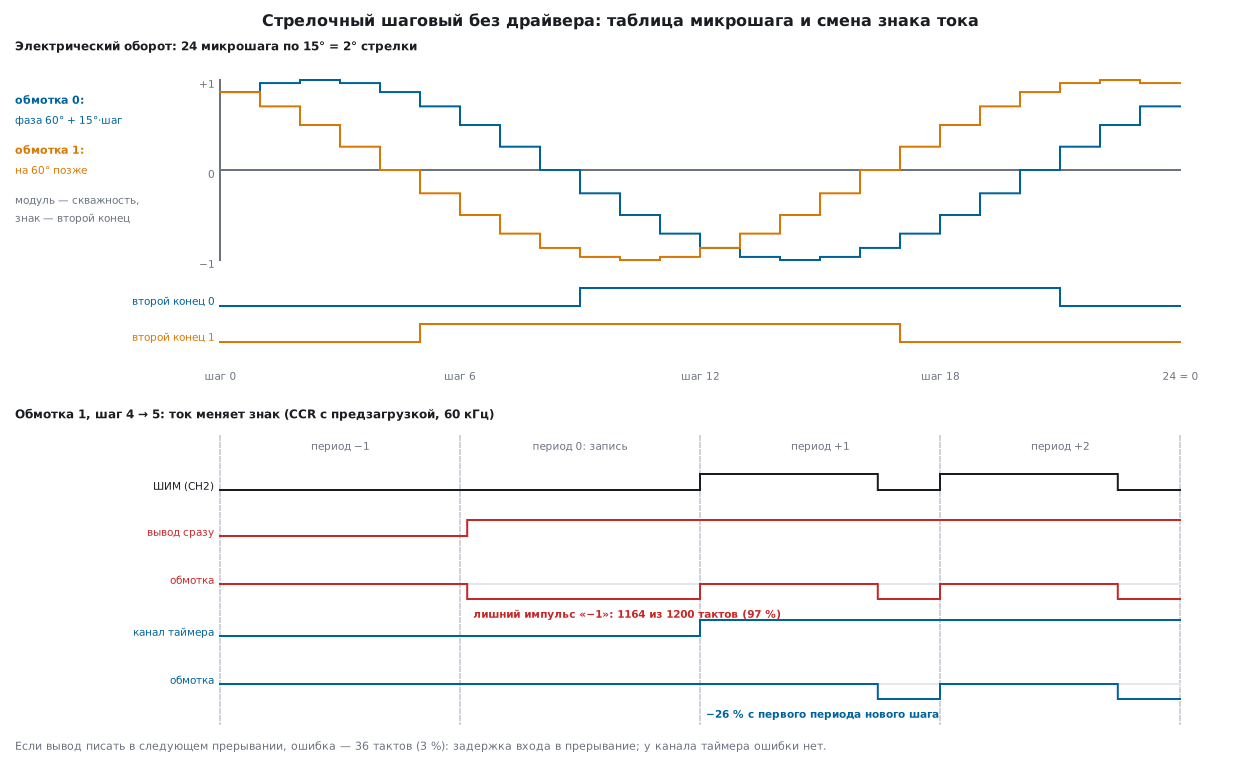
Why you can drive it straight from the pins. In 57е a 1.5 Ω winding gets 24 V; without a limit the current would grow to 16 A, so the driver chops it. For the gauge motor the AN gives a current of about 20 mA. There is no X25.689 datasheet in the project, but there are datasheets of motors with the same geometry (57ж.2): the VID29 winding is 260…300 Ω (typically 280) at 25 °C, supply 5…10 V. From 5 V that is 17.9 mA. The winding itself limits the current: you can apply the full voltage and nothing burns. So there is no need to regulate the current; it is enough to regulate the average voltage with PWM: the winding averages it, and the current is proportional to the duty cycle (57.5 explains why the current does not follow the voltage instantly, 57ж.3 shows by how much). 57а.3 warned that plain voltage PWM loses torque at speed; a needle needs neither the torque nor the speed of a machine tool, so this does not matter.
57ж.2 Gauge motor geometry: 12 microsteps per degree
Inside the X25.689 is a small magnet rotor and a 1/180 gearbox (AN3208, section 4). A full rotor step is 180°, and it becomes 1° of the needle. A full step splits into 3 partial steps (1/3°, the "resolution" from the feature list in the AN), each partial step into 4 microsteps. In total:
- 12 microsteps per degree of the needle, one microstep is 1/12°;
- a full rotor turn (360°, one electrical period) is 24 microsteps, that is 2° of the needle;
- the needle travel 0…320° (as in the AN) is 3840 microsteps, or 160
electrical periods; the AN counts this travel with the variable
Rotation_Noup to 160.
The VID29 has the same geometry (datasheet, p. 2–3: gearbox 180:1, steps of 1°, 1/3° and 1/12°; rotor 180°, 60° and 15°), and so does the X40 (p. 2: electrical period 2°, 1:180, phase shift 60°). But both have the internal stop at 315°, so our scale is 0…300°: 3600 microsteps, 150 electrical periods (57ж.6).
What is special about this motor: the currents of the two windings are
offset not by 90°, as in 57а.3, but by 60°. The table is built like
this: at microstep k (0…23) the phase of winding 0 is 60° + 15°·k, that
of winding 1 is 60° more; the current is the sine of the phase. The
magnitude goes into the PWM duty cycle, the sign into the current direction.
We do not type the table by hand: a quarter sine in 15° steps is seven
numbers in Q15 (32768·sin(15°·k): 0, 8481, 16384, 23170, 28378, 31651,
32768), the code computes the rest. The sign at zero is a convention: a
phase in (0°, 180°] is "+", in (180°, 360°] it is "−", so at zero the winding
keeps the sign of the half-wave it has just finished. The AN does the same:
of the 25 rows of its Table 2, the second-end level matches the sign from
this rule in all 25. The AN numbers things its own way: steps from 1,
row 25 repeats row 1, windings 1 and 2. Our step k is its step k + 1,
our windings 0 and 1 are its 1 and 2.
/* Ток обмотки coil (0 или 1) на микрошаге idx (0…23): модуль в Q15 и знак.
 * Фаза обмотки 0 — 60° + 15°·idx, обмотки 1 — на 60° больше. Знак «+» — фаза в (0°, 180°],
 * «−» — в (180°, 360°]: в нуле обмотка остаётся на знаке той полуволны, которую закончила. */
int8_t gauge_level(uint8_t idx, uint8_t coil, uint16_t *mag)
{
    uint8_t j = (uint8_t)((idx + 4u + 4u * coil) % GAUGE_USTEPS);   /* фаза в шагах по 15° */
    uint8_t q = j % 12u;
    *mag = gauge_sin_q15[q <= 6u ? q : 12u - q];
    return (j >= 1u && j <= 12u) ? 1 : -1;
}
The first 12 microsteps (the second half is the same with the opposite sign); CCR is for the F103 with a period of 1200 clocks (57ж.5) and full amplitude, as in the AN:
| Step | Phase 0 | Phase 1 | Current 0 (Q15) | Current 1 (Q15) | Second end 0 / 1 | CCR 0 / 1 |
|---|---|---|---|---|---|---|
| 0 | 60° | 120° | 28378 | 28378 | 0 / 0 | 1039 / 1039 |
| 1 | 75° | 135° | 31651 | 23170 | 0 / 0 | 1159 / 849 |
| 2 | 90° | 150° | 32768 | 16384 | 0 / 0 | 1200 / 600 |
| 3 | 105° | 165° | 31651 | 8481 | 0 / 0 | 1159 / 311 |
| 4 | 120° | 180° | 28378 | 0 | 0 / 0 | 1039 / 0 |
| 5 | 135° | 195° | 23170 | −8481 | 0 / 1 | 849 / 889 |
| 6 | 150° | 210° | 16384 | −16384 | 0 / 1 | 600 / 600 |
| 7 | 165° | 225° | 8481 | −23170 | 0 / 1 | 311 / 351 |
| 8 | 180° | 240° | 0 | −28378 | 0 / 1 | 0 / 161 |
| 9 | 195° | 255° | −8481 | −31651 | 1 / 1 | 889 / 41 |
| 10 | 210° | 270° | −16384 | −32768 | 1 / 1 | 600 / 0 |
| 11 | 225° | 285° | −23170 | −31651 | 1 / 1 | 351 / 41 |
57ж.3 Motor datasheet: current, inductance, steps
There is no X25.689 datasheet in the project. There is the datasheet of the VID29 (Wellgain), a motor with the same geometry, the datasheet of the VID66-08 driver made for it, and the datasheet of the X40 (Juken), two needles on one axis (57ж.9). They let you check what the AN leaves vague.
Current and cold. The VID29 winding is 260…300 Ω at 25 °C (datasheet, p. 3), and per the VID66-08 driver datasheet (p. 5) it is about 190 Ω at −40 °C and 340 Ω at 105 °C; the X40 has 230…290 Ω (p. 2). The recommended VID29 peak current is from 12.9 to 16.07 mA (p. 7). At full duty cycle from 5 V:
| Winding | From 5 V | From 5 V, amplitude 3/4 | From 3.3 V |
|---|---|---|---|
| VID29, 260 Ω (25 °C, minimum) | 19.2 mA | 14.4 mA | 12.7 mA |
| VID29, 280 Ω (25 °C, typical) | 17.9 mA | 13.4 mA | 11.8 mA |
| VID29, 300 Ω (25 °C, maximum) | 16.7 mA | 12.5 mA | 11.0 mA |
| VID29, 190 Ω (−40 °C) | 26.3 mA | 19.7 mA | 17.4 mA |
| VID29, 340 Ω (105 °C) | 14.7 mA | 11.0 mA | 9.7 mA |
| X40, 230 Ω (minimum) | 21.7 mA | 16.3 mA | 14.3 mA |
From 5 V in the cold it is 26.3 mA: above the 20 mA pin limit and above
the recommended peak. So the firmware limits the amplitude: the sine peak is
3/4 of the period (AMP = 900 of 1200 on the F103, 100 of 134 on the STM8),
and gauge_coil got an amp parameter. For 20 mA in the cold 0.76 would
be enough; with 0.75 it is 19.7 mA at −40 °C, 12.5…14.4 mA at 25 °C, near
the lower end of the recommended range, and 11.0 mA at 105 °C. The tables in
this section that compare with the AN use full amplitude.
/* Обмотка между выводом ШИМ и вторым выводом: напряжение на ней — ШИМ минус второй вывод.
 * При io = 0 доля «+» за период — CCR/period; при io = 1 доля «−» — (period − CCR)/period:
 * скважность для отрицательного тока переворачивается. period = ARR + 1.
 * amp — сколько тактов из period даёт пик синуса: amp < period ограничивает ток обмотки. */
void gauge_coil(uint8_t idx, uint8_t coil, uint16_t period, uint16_t amp, coil_t *o)
{
    uint16_t mag;
    int8_t sign = gauge_level(idx, coil, &mag);
    uint16_t d = (uint16_t)(((uint32_t)mag * amp + 16384u) >> 15);
    o->io = sign < 0;
    o->ccr = o->io ? (uint16_t)(period - d) : d;
}
Inductance. The VID66-08 datasheet (p. 5) gives a phase inductance of
0.4 H. With 280 Ω the time constant τ = L/R is 1.429 ms: over one
60 kHz PWM period (16.667 µs) the current barely changes; the ripple at a
duty cycle of 1/2 is only 52.1 µA, 0.58 % of the current. So the duty
cycle really does set the current. But settling takes 3τ = 4.29 ms, and a
microstep at speed is shorter. A model of the winding as an RL circuit under
the same PWM and the same table (amplitude 3/4, steps from the accumulator,
as in gauge_tick) at different needle speeds:
| Pointer speed | Microstep | Microstep / τ | Current, first harmonic | Lag | First-order RL |
|---|---|---|---|---|---|
| 125°/s | 666.7 µs | 0.467 | 0.871 | 29.1° | 0.872 / 29.3° |
| 200°/s | 416.7 µs | 0.292 | 0.744 | 41.6° | 0.744 / 41.9° |
| 400°/s | 208.3 µs | 0.146 | 0.486 | 60.3° | 0.487 / 60.9° |
| 600°/s | 138.9 µs | 0.097 | 0.348 | 68.7° | 0.348 / 69.6° |
The first harmonic of the current drops and lags exactly as with a
first-order RL filter 1/√(1 + (ωτ)²): at 600°/s a microstep of 138.9 µs is
0.097 τ, the current reaches only 0.348 of the target and lags by 68.7°. The
ratio of the harmonics at 400 and 200°/s is 0.654; for the VID29 rated
dynamic torque (p. 3: 0.85 and 1.2 mN·m typical) it is 0.708: the same trend.
The model has no rotor back-EMF.
Start frequency and end stop. The VID29 start-stop frequency is 125 Hz of full steps (p. 3), and a full step is 1° of the needle, so it is 125°/s, 1500 microsteps/s; the X40 has 200°/s (p. 2). Faster only with a ramp (up to 600°/s for both). Our ramp (57ж.6) starts at 30 microsteps/s (2.5°/s) and stops from a speed of at most 300 (25°/s), below both. The travel with the internal stop is 315° (VID29, p. 3; X40, p. 2). The VID29 datasheet (p. 8): the scale is usually below 300°, zero is set by the stop at every power-up, and the ramp starts from the start frequency.
VID29 steps instead of a sine. The microstep example in the VID29
datasheet (p. 7) is not a sine but a staircase of equal steps: six per
quarter wave, 0; 3.33; 6.67; 10; 13.33; 16.67; 20 (the example peak is
16.07 mA), the right winding shifted by 4 microsteps, 60°. If the rotor is
assumed to settle at the phase of the AN sine model (i0 = A·sin φ,
i1 = A·sin(φ + 60°)), then:
| Table | Phase error, el. deg | Same on the needle | Magnitude A, from … to |
|---|---|---|---|
| VID29 staircase | 10.89 | 0.0605° | 0.6667…1.0184 |
| Q15 sine (ours) | 0.00 | 0.0000° | 1.0000…1.0000 |
The steps shift the position by up to 10.89 electrical degrees, 0.0605° of the needle against a microstep of 0.0833°, and the magnitude "dances" by 34.5 %. The sine from seven Q15 numbers does not do that.
Partial step on three pins, no PWM. The VID29 datasheet (p. 6–7) describes the simplest mode: contacts 2 and 3 tied together, the motor on three logic pins, six states per electrical period, a 1/3° step. We derived our own sequence from the same model: the left winding voltage is contact 1 minus contacts 2+3, the right one is contact 4 minus the same:
/* Частичный шаг без ШИМ (паспорт VID29, с. 6–7): контакты 2 и 3 соединены, двигатель на трёх выводах.
 * Бит 2 — контакт 1, бит 1 — контакты 2 и 3, бит 0 — контакт 4. Шесть состояний на электрический
 * оборот, за шаг меняется один вывод; шаг — 60° ротора, 1/3° стрелки. */
const uint8_t gauge_partial[6] = { 0x1, 0x5, 0x4, 0x6, 0x2, 0x3 };
| Step | Contact 1, 2+3, 4 | Left / right winding | Phase | Magnitude | Common pin current |
|---|---|---|---|---|---|
| 0 | 0 0 1 | 0 / +1 | 0° | 1.1547 | 17.9 mA |
| 1 | 1 0 1 | +1 / +1 | 60° | 1.1547 | 35.7 mA |
| 2 | 1 0 0 | +1 / 0 | 120° | 1.1547 | 17.9 mA |
| 3 | 1 1 0 | 0 / −1 | 180° | 1.1547 | 17.9 mA |
| 4 | 0 1 0 | −1 / −1 | 240° | 1.1547 | 35.7 mA |
| 5 | 0 1 1 | −1 / 0 | 300° | 1.1547 | 17.9 mA |
The phase advances by exactly 60°, the magnitude is constant at 1.1547, one pin changes per step. But in two states of the six the common pin 2+3 carries the current of both windings: at 280 Ω that is 35.7 mA, twice any other pin and above the 20 mA pin limit. Put the common end on two pins in parallel or through a buffer.
Needle and direction. A VID29 needle is up to 80 mm and 10 g, unbalance up to 0.025 mN·m (p. 6): 2.9 % of the typical torque at 400 Hz and 0.7 % of the 3.5 mN·m holding torque. The start frequency is given for a needle of 0.2·10⁻⁶ kg·m² (p. 3). Shaft acceleration up to 1000 rad/s² (p. 4); ours is 2500°/s², which is 43.6 rad/s². Backlash is 0.5…1.0°. The VID29-XX and the VID29-XXP (p. 6, 8) differ by mirrored wiring: the same sequence turns them in opposite directions.
57ж.4 Winding = PWM + pin: the duty cycle inverts
There is no bridge. One end of the winding is on a PWM channel, the other on an ordinary pin (AN3208, section 4: each winding has one PWM line and one I/O line). The winding voltage is PWM minus the pin:
| Second end | PWM = 1 | PWM = 0 | Average over the period |
|---|---|---|---|
| 0 | +V | 0 | +V·d |
| 1 | 0 | −V | −V·(1 − d) |
d is the fraction of the period the PWM output is high,
d = CCR/(ARR + 1). With the second end high, the negative voltage appears
while the PWM is low. So for a current of "−m" you write
CCR = (1 − m)·(ARR + 1), not m·(ARR + 1). That explains the "odd" value
in the AN's Table 2: step 6 (our 5), winding 2, duty cycle 26 %, yet the
register holds 0x63 = 99 of 134, which is (1 − 0.26)·134 = 99.16. For zero
with the second end high you need CCR = ARR + 1 (PWM high all the time), not
0; in the AN that is 0x86 = 134. The F103 can do this too: per RM0008, with
CCR > ARR in PWM mode 1 the output stays high. With amp below the period
(57ж.3) this does not change: the magnitude is taken from amp, the
inversion from the period.
Checking Table 2 of AN3208. The STM8 timer in the AN runs at 8 MHz with
ARR = 0x85, a period of 134 clocks. Each of the 50 CCR values of Table 2
was recomputed with Equation 1 in three ways (ref57zh.py):
| How it is computed | Matches the AN |
|---|---|
| duty cycle from Table 1 (two digits), drop the fraction | 50 of 50 |
| duty cycle from Table 1, rounded | 32 of 50 |
exact sine, rounded (our gauge_coil) |
34 of 50 |
So the AN took the sine rounded to two digits and dropped the fraction.
Example: step 8 (our 7), winding 2, 71 % with the second end high:
(1 − 0.71)·134 = 38.86, the AN has 0x26 (38), rounding would give 0x27,
and the exact sine of 225° also gives 0x27. Dropping the fraction never
increases CCR, and for a negative current a smaller CCR means a larger
magnitude. The two halves of the wave come out unequal: at 87 % "+" gives
116/134 = 0.8657 and "−" gives 1 − 17/134 = 0.8731, a difference of up to
0.75 percentage points. In gauge_coil the CCR for "−" is period − d, and
the halves are exactly equal.
Where the AN contradicts itself. The data were checked against the PDF (gauge57zh_check.py):
- The explanation of Table 1 for step 2 gives the magnitude of winding 1 as 0.71 and of winding 2 as 0.97; Table 1 itself and Table 2 have it the other way round: 0.97 and 0.71. The table is right: the phases of step 2 are 75° and 135°, the sines 0.97 and 0.71.
- Section 5.2.2: the top speed is 7200 microsteps/s, so the interval is at least 139 µs (calculated: 138.889). Three sentences later it says "minimum limit of 300 µs". Where 300 comes from is not explained; by calculation the limit is 139.
- In the same place the PWM period is given as 16.6 µs and the step as
830 µs (50 periods). At 8 MHz and
ARR= 0x85 the frequency is 59.701 kHz, the period 16.750 µs, 50 periods 837.5 µs. The "60 kHz" in the AN is rounded. - The motor features in section 4: "high speed (greater than 600°/s)"; section 5.2.2: "the maximum is 600 full steps per second", and a full step is 1° of the needle. The AN's limit is above 600°/s in one place and exactly 600 in the other. The VID29 datasheet (p. 3) gives exactly 600 Hz of full steps.
- The 0…320° travel in the AN: the VID29 and the X40 have the stop at 315° (57ж.6).
The rule of this section is the same as with datasheets: where a document argues with itself, trust the calculation. Do not copy the table from the AN; compute it from the sine and the period of your own timer.
57ж.5 On the STM32F103: TIM2 at 60 kHz and the preload trap
On a BluePill the timers run from 72 MHz (TIM2…TIM4 sit on APB1 at 36 MHz,
but when the APB1 prescaler is not 1 the timer gets twice the frequency).
60 kHz means ARR = 1199, a period of 1200 clocks: exactly 60000 Hz,
a period of 16.667 µs. A microstep every 50 periods, as in the AN, is
833.333 µs, the whole 0…300° scale is 3000 ms. CCR = 1200 gives 100 %.
The "as in the AN" variant: the windings on TIM2 CH1 (PA0) and CH2 (PA1), the second ends on pins PB12 and PB13. The TIM2 update interrupt, once per PWM period, counts the microsteps and writes the new CCR values.
The trap. PWM mode needs CCR preload (OCxPE; RM0008: "the user must
enable the corresponding preload register"): a CCR you write takes effect
only at the next update event, while a pin written through GPIOB->BSRR
changes immediately. If one interrupt writes both the CCR and the pin, then
until the end of the current period the winding sees the new second end
and the old CCR. The worst case is a sign change: the old zero is
written as CCR = 0 with the second end at 0 (PWM low all the time), the
second end goes to 1, and the winding gets −V for almost the whole period
instead of −26 %. The timer model in the bench (CCR takes effect at the
update, the pin immediately, the write lands 36 clocks after the update,
0.5 µs, an assumption for interrupt entry, 7а) over one electrical period:
| How the sign changes | Sign changes | Periods with an error | Worst error per period |
|---|---|---|---|
| pin immediately, in the same interrupt | 4 | 4 | 1164 clocks of 1200 (97.0 %) |
| pin in the next interrupt | 4 | 4 | 36 clocks (3.0 %) |
| second end on a channel of the same timer | 4 | 0 | 0 |
The error is an extra pulse at every sign change, four times per 24 microsteps, that is, per 2° of the needle. The inductance (57ж.3) smooths it but does not remove it: it is a kick in the winding that you can see on a scope. There are two fixes.
Pin in the next interrupt. The next update interrupt is exactly the moment when the new CCR values took effect. Only the entry delay remains: those 36 clocks in the model. Microsteps come no more often than once every 8 periods even at 7200 microsteps/s (57ж.6), so the deferred write is always in time.
/* Микрошаг в TIM2 и выводы. CCR вступят на следующем обновлении, а запись в BSRR — сразу,
 * поэтому выводы откладываем до следующего прерывания: оно и есть это обновление. */
static void gauge_out(uint32_t i, uint8_t now)
{
    coil_t a, b;
    uint8_t idx = gauge_index(&mv[i]);
    gauge_coil(idx, 0, PERIOD, AMP, &a);
    gauge_coil(idx, 1, PERIOD, AMP, &b);
    TIM2->CCR1 = a.ccr;
    TIM2->CCR2 = b.ccr;
    io_next = (a.io ? GPIO_BSRR_BS12 : GPIO_BSRR_BR12) | (b.io ? GPIO_BSRR_BS13 : GPIO_BSRR_BR13);
    if (now) {
        GPIOB->BSRR = io_next;
        io_next = 0;
    }
}

void TIM2_IRQHandler(void)
{
    TIM2->SR = (uint16_t)~TIM_SR_UIF;
    if (io_next) {                 /* CCR из прошлого прерывания только что вступили — теперь выводы */
        GPIOB->BSRR = io_next;
        io_next = 0;
    }
    if (gauge_tick(&mv[0]))
        gauge_out(0, 0);
    idle = mv[0].pos == mv[0].target && mv[0].v == 0;
}
The second end is a timer channel too. A channel in PWM mode with CCR = 0 is a constant zero, with CCR = 1200 a constant one, and it is preloaded as well. Then the duty cycle and the direction take effect at the same update, and there is no error at all (the third row of the table). The price is four channels per needle instead of two; TIM2 has exactly four: PA0…PA3. This is how the main firmware works (57ж.7).
57ж.6 The needle: speed, ramp and zero without a sensor
Speed limit. AN3208 gives 600 full steps per second, that is 7200 microsteps/s, an interval of 138.889 µs. But here the step clock is the PWM period itself, 60 kHz: an interval can only be a whole number of periods. The nearest one not shorter than the limit is 9 periods, 150 µs, 6666.667 microsteps/s. If you set exactly 7200 microsteps/s through the accumulator (below), the intervals come out as 8 and 9 periods, and 8 periods is 133.333 µs, shorter than the limit: in the run over 0…300° there are 1331 such intervals. The firmware uses, with margin, 6000 microsteps/s (500°/s), exactly 10 periods.
Ramp. In 57а.4 the speed is set by the interval of a step timer: ARR
is recomputed on every step. That is not possible here: ARR is taken by
the 60 kHz PWM. So a phase accumulator makes the steps: every PWM period the
speed (microsteps/s) is added to it, and when it reaches 60000, a step.
The speed is recalculated once per millisecond: not above vmax and not
above the speed from which you can still stop, v² ≤ 2a·distance, and it
changes by at most dv per millisecond. If the target ends up behind, the
same formula brakes and turns around.
/* Раз в миллисекунду. Скорость к цели — не больше vmax и не больше той, с которой ещё успеем
 * встать: v² <= 2a·путь. Меняется не больше чем на dv за миллисекунду — это и есть разгон,
 * торможение и разворот, если цель оказалась позади. Путь — до 71582 микрошагов (2000·dv·путь в 32 битах при dv = 30). */
static void gauge_speed(gauge_move_t *m)
{
    int32_t dist = m->target - m->pos;
    uint32_t d = (uint32_t)(dist < 0 ? -dist : dist);
    uint32_t ahead = ((uint32_t)(m->v < 0 ? -m->v : m->v) + 999u) / 1000u;   /* пройдём за эту миллисекунду */
    uint32_t lim = isqrt32(2000ul * m->dv * (d > ahead ? d - ahead : 0u));    /* 2000ul: 16-битный int переполнился бы уже при dv = 33 */
    if (lim > m->vmax)
        lim = m->vmax;
    int32_t want = dist < 0 ? -(int32_t)lim : (int32_t)lim;
    if (want > m->v + m->dv)
        want = m->v + m->dv;
    else if (want < m->v - m->dv)
        want = m->v - m->dv;
    m->v = want;
}
The firmware acceleration is 30000 microsteps/s², that is 2500°/s². The run
(dv = 30, vmax = 6000):
| Move | Time in the model | Ideal trapezoid | What you see |
|---|---|---|---|
| 0 → 300° | 796.567 ms | 800.0 ms | ramp of 597 steps (ideally 600 = 50° in 200 ms), no overshoot, stops at 114 microsteps/s |
| 300° → 0 | 797.000 ms | 800.0 ms | the same in the other direction |
| to 300°, after 300 ms to 50° | 897.000 ms | — | reaches 150° (1800 microsteps), brakes and comes back |
At the target the needle stops if the speed is not above 300 microsteps/s
(GAUGE_VSTOP), instead of braking to zero. That is where the gain over the
trapezoid comes from: 800.0 − 796.567 = 3.433 ms, about the time to
brake from 114 microsteps/s to zero, 114/30000 s = 3.8 ms. The needle both
starts and stops below the start-stop frequency (57ж.3).
Zero without a sensor. The needle has no position sensor; the pos
count means nothing after power-up. The solution is a mechanical stop at
zero: the needle is driven back for the full mechanical travel of 315° plus a
margin, here 325° (3900 microsteps, a 10° margin), and wherever it was, it
reaches the stop and stays there for the rest of the way: the rotor slips,
the needle does not. Then the count is reset. The homing speed is 1500
microsteps/s, 125°/s: the VID29 start-stop frequency, homing takes 2644.650 ms
(trapezoid: 2650.0). In the model the needle starting from 0°, 100° and 315°
ended at zero every time; the steps "lost" against the stop were 3900, 2700
and 120.
/* Поиск нуля без датчика: считаем, что стрелка на 325°, и ведём её в 0. Где бы она ни была,
 * она дойдёт до упора и простоит в нём остаток пути: ротор проскальзывает, стрелка — нет. */
void gauge_home(gauge_move_t *m)
{
    m->pos = GAUGE_HOME;
    m->target = 0;
    m->v = 0;
    m->acc = 0;
    m->ms = 0;
}
This only works with a motor that has an internal stop. Per the Juken catalogue (vers. 4.1, p. 1) the X27.579 and the X27.679 have no stop, the X27.589 and the X27.689 do; the X10.504 and its neighbours (p. 2) have holes for zero detection, which is another approach, with a sensor. The X25.689 is not in the catalogue. And the scale must end before the stop: the AN travel to 320° on a motor with the stop at 315° loses 60 microsteps in the model, and afterwards a needle sent to 150° shows 145° (−60 microsteps), until the next homing.
Instrument clusters home the needles at every power-up (VID29 datasheet,
p. 8): the needles go to the stop, then sweep the scale to the end and come
back. The driver sees an "instrument check", and the firmware has found zero
in the meantime. fw57zh.c does the same: homing, a sweep to 300° and back.
57ж.7 Four needles on one chip
In AN3208 the STM8 drives four needles: eight PWM channels (four from TIM1, two from TIM2 with the third one free, and two from TIM3) plus eight pins. The F103 does it differently: each needle has its own timer and all four of its channels (57ж.5, the second end is a channel), with no ordinary pins:
| Needle | Timer | CH1 | CH2 | CH3 | CH4 |
|---|---|---|---|---|---|
| 0 | TIM1 | PA8 | PA9 | PA10 | PA11 |
| 1 | TIM2 | PA0 | PA1 | PA2 | PA3 |
| 2 | TIM3 | PA6 | PA7 | PB0 | PB1 |
| 3 | TIM4 | PB6 | PB7 | PB8 | PB9 |
CH1 and CH3 are winding 0, CH2 and CH4 are winding 1. The pins follow Table 5
of DocID13587 without remapping. PA11 is also USB D−: with USB the fourth
needle has to move. On TIM1 the outputs are opened by the MOE bit.
There is one interrupt, the TIM2 update, once per PWM period, and it writes
to all four timers. The counters are started almost together but are not
linked: if the TIM3 update falls between the writes of its CCR1 and CCR4,
one winding gets the new value and the other the old one. So UDIS is set
for the duration of the write (RM0008: "the update event is not generated,
shadow registers keep their value"), and an update that falls into the
write simply moves everything one period later.
/* Микрошаг в таймер стрелки i: все четыре CCR вступят на одном обновлении. Пока пишем, стоит UDIS:
 * обновление посреди записи не перенесёт половину значений, а подождёт до следующего периода. */
static void gauge_out(uint32_t i, uint8_t now)
{
    TIM_TypeDef *t = tim[i];
    coil_t a, b;
    uint8_t idx = gauge_index(&mv[i]);
    (void)now;
    gauge_coil(idx, 0, PERIOD, AMP, &a);
    gauge_coil(idx, 1, PERIOD, AMP, &b);
    t->CR1 |= TIM_CR1_UDIS;
    t->CCR1 = a.ccr;
    t->CCR3 = a.io ? PERIOD : 0u;
    t->CCR2 = b.ccr;
    t->CCR4 = b.io ? PERIOD : 0u;
    t->CR1 &= (uint16_t)~TIM_CR1_UDIS;
}

void TIM2_IRQHandler(void)
{
    uint8_t s = 0;
    TIM2->SR = (uint16_t)~TIM_SR_UIF;
    for (uint32_t i = 0; i < N; i++) {
        if (gauge_tick(&mv[i]))
            gauge_out(i, 0);
        if (mv[i].pos == mv[i].target && mv[i].v == 0)
            s |= (uint8_t)(1u << i);
    }
    idle = s;
}
At 72 MHz and 60 kHz there are 1200 clocks per period; how many of them the
interrupt with four needles takes was not measured. Build:
arm-none-eabi-gcc 12.2.1 with -Os -Wall -Wextra -Werror and the CMSIS
header stm32f10x.h: fw57zh.o is 724 bytes of code for four needles
and 528 for one with pins, gauge57zh.o is 408; the whole image
with the startup code is 1376 and 1180 bytes. Of that, gauge_tick
is 228, the TIM2 handler 76 and 88.
Current. The F103 pins are 3.3 V. With the rated resistances (57ж.3) the
winding gets 11.8 mA at 280 Ω and 11.0 mA at 300 Ω, below the recommended
12.9 mA, and that is before the pin voltage drop. And per DocID13587 a pin
handles ±8 mA with normal levels and ±20 mA with "relaxed" ones: at 20 mA a
high level may drop to VDD − 1.3 V and a low level rise to 1.3 V. The limit
for the whole package is 150 mA, and it is not the problem: four needles in
the cold (17.4 mA per winding) draw 120.3 mA. The voltage is the problem.
So, as in the AN, a 74HC244 buffer on 5 V sits between the pins and the
windings: eight outputs, two needles per package. The supply pin of the
package carries the current of both needles: with amplitude 3/4 in the cold,
up to 34.2 mA per needle, 68.4 mA for two. A 74HC244 typically allows ±35 mA
per output and ±70 mA per supply and ground pin; these are typical figures,
not from a datasheet (there is none in the project): before putting two
needles on one package, check yours.
57ж.8 On the STM8S003 from 5 V: no level shifter and no regulator
Why 5 V. Gauge motors of this class are rated for 5 V and above (VID29 5…10 V, X40 5…9 V). The F103 puts 3.3 V on its pins: either a 5 V buffer plus a 3.3 V regulator for the F103 itself, or the motor at reduced current (57ж.7). The STM8S003F3 runs from the same 5 V as the motor: no regulator, no level shifter. AN3208 says as much in the X25.689 features: the motor can be driven directly by a microcontroller; so does the VID29 datasheet (p. 1).
Pin currents. Per the STM8S003F3/K3 datasheet (DocID018576 Rev 8):
- the pin limit is 20 mA both sunk and sourced; the current into the VDD pins is at most 100 mA, out of the VSS pins at most 80 mA (p. 48);
- on the high sink pins (p. 69) at 5 V and 20 mA with four pins loaded, high is not below 3.3 V and low not above 1.5 V, so the winding is guaranteed 1.8 V; at 10 mA with eight pins it is 4.0 and 0.8 V, that is 3.2 V. Standard pins at 10 mA with eight pins give 2.8 and 2 V (p. 68): 0.8 V;
- PC3 (
TIM1_CH3), PC4 (TIM1_CH4), PD2 and PD3 are high sink pins (p. 27–28 for the F3, p. 23–24 for the K3), and such pins must be spread uniformly around the package.
How much one needle draws: the winding currents are 60° apart, and the sum of their magnitudes peaks where both are 0.866, at 1.7321 of full current. With an amplitude of 100 of 134 (0.7463) in the cold a winding takes 19.6 mA and a needle 34.0 mA: two take 68.0 mA and fit into the 80 mA on VSS; three take 102.0 mA and do not (at 25 °C three would fit, 69.2 mA, but not in the cold). Without the 3/4 amplitude a winding in the cold would take 26.3 mA, above the pin limit.
Timers. The "3 timers" in the datasheet title (p. 1) are TIM1 with four channels, TIM2 with three and the basic TIM4; TIM3, which gives the STM8 in the AN two more channels, is not mentioned in the S003 datasheet at all, and the vector table (p. 41) lists only TIM1, TIM2 and TIM4. A needle needs 2 PWM channels and 2 pins: by channels that makes 3 needles, two on TIM1 and one on TIM2, with 1 TIM2 channel left over. A fourth needle needs two more channels: there is no hardware PWM for it, only software PWM. By current, straight from the pins, it is 2 needles; three go through a buffer, but on the same 5 V, with no level shifting.
Frequency. The clock is the internal HSI RC oscillator at 16 MHz
(datasheet, p. 1; RM0016, p. 81). After reset CLK_CKDIVR = 0x18, an HSI
divider of 8 and 2 MHz (RM0016, p. 94); the firmware writes 0. The TIM1
counter runs at fCK_PSC/(PSCR + 1) (RM0016, p. 142). The options around
60 kHz:
| PSCR | Counter clock | ARR | Period | Frequency | Deviation from 60 kHz |
|---|---|---|---|---|---|
| 0 | 16 MHz | 265 | 266 | 60.150 kHz | +0.251 % |
| 0 | 16 MHz | 266 | 267 | 59.925 kHz | −0.125 % |
| 1 | 8 MHz | 132 | 133 | 60.150 kHz | +0.251 % |
| 1 | 8 MHz | 133 (0x85) | 134 | 59.701 kHz | −0.498 % |
The closest to 60 kHz is PSCR = 0 with ARR = 266, and its CCR is twice as
fine. The AN uses PSCR = 1 and 0x85, the farthest of the four: even at 8 MHz
ARR = 132 is closer. The firmware still takes the AN setting, so its CCR
values at full amplitude compare with Table 2 directly: these are the
ccr134 rows of the bench, 34 of 50 matched, the other 16 are the AN's
dropped fraction (57ж.4). The motion code assumes a 60 kHz tick, but it is
59701.5 Hz: all speeds are 0.5 % lower (6000 → 5970.1 microsteps/s, 10
periods are 167.5 µs).
Alignment: two traps. The first is the same as on the F103: CCR is
preloaded (OCxPE in TIM1_CCMRx) and takes effect at the update, while
PD_ODR changes immediately; the pins are written in the next interrupt. The
second is specific to the STM8: CCR is 16-bit, but it is written byte by
byte. RM0016 (§17.5.1, p. 167; for ARR §17.3.2, p. 142, the same for PSCR):
the high byte goes first; writing it locks the transfer to the shadow
register until the low byte is written; do not use the LDW instruction, it
writes the low byte first. If the low byte is written first, its write
releases the lock, the high-byte write that follows locks it again, and the
next update has nothing to transfer. In a model built from this description,
with the reverse order 44 of the 48 CCR values per period (two windings)
never reach the timer, at both 134 and 267 periods; with the right order, 0.
The firmware writes through the CCR_WRITE macro, and the SDCC listing shows
the order: 0x5269 (TIM1_CCR3H) before 0x526A (TIM1_CCR3L), 0x526B before
0x526C, and PD_ODR (0x500F) after them; PSCR and ARR in main also go high
byte first, and there is not a single LDW to the TIM1 registers.
/* 16-битный CCR у TIM1 STM8 пишут двумя байтами, старший первым: старший ждёт в буфере, запись
 * младшего переносит оба. Обратный порядок даёт CCR со старым старшим байтом. */
#define CCR_WRITE(H, L, v) do { H = (uint8_t)((v) >> 8); L = (uint8_t)(v); } while (0)

static void gauge_out(uint8_t now)
{
    coil_t a, b;
    uint8_t idx = gauge_index(&mv);
    gauge_coil(idx, 0, PERIOD, AMP, &a);
    gauge_coil(idx, 1, PERIOD, AMP, &b);
    CCR_WRITE(TIM1_CCR3H, TIM1_CCR3L, a.ccr);   /* вступят на следующем обновлении */
    CCR_WRITE(TIM1_CCR4H, TIM1_CCR4L, b.ccr);
    io_next = (uint8_t)((a.io ? 0x04u : 0u) | (b.io ? 0x08u : 0u));
    io_pending = 1;
    if (now) {
        PD_ODR = (uint8_t)((PD_ODR & (uint8_t)~IO_MASK) | io_next);
        io_pending = 0;
    }
}

void tim1_update_isr(void) __interrupt(TIM1_IRQ_UPD)
{
    TIM1_SR1 = (uint8_t)~SR1_UIF;
    if (io_pending) {                           /* CCR из прошлого прерывания только что вступили */
        PD_ODR = (uint8_t)((PD_ODR & (uint8_t)~IO_MASK) | io_next);
        io_pending = 0;
    }
    if (gauge_tick(&mv))
        gauge_out(0);
    idle = mv.pos == mv.target && mv.v == 0;
}
The shared logic under SDCC. gauge57zh.c built with SDCC without any
change in meaning, but with two portability fixes: SDCC for the STM8 has a
16-bit int. 1u << 30 in isqrt32 is not 2³⁰ there, and 2000u * dv
would overflow already at dv = 33. Now it is (uint32_t)1 << 30 and
2000ul.
All 23 register addresses in regs57zh_stm8.h were checked against the
register map of the S003 datasheet (p. 31–37), the TIM1 vector is IRQ 11
(p. 41). Do not take the map from a neighbouring device: on the STM8S105
(DocID14771) TIM2_IER is at 0x5301, on the S003 at 0x5303.
Built with SDCC 4.2.0, --std-c99 --opt-code-size: the code is 2083
bytes, 2191 in flash in total (with the vector table, initialization
and constants), RAM 24 bytes. Of the code, 452 bytes are 32-bit arithmetic
from the SDCC library (multiply, divide, remainder), gauge57zh.c is 1242
bytes against 408 on the Cortex-M3, fw57zh_stm8.c is 389. There is no
ucsim simulator in the stm-sdcc:1 image, so the firmware was not run; the
CCR values it writes are gauge_coil with a period of 134, but the
execution of the SDCC code was not checked.
57ж.9 The VID6608 driver and two needles on one X40 axis
The third path: a driver. Besides "straight from the pins" and "through
a buffer", there is a driver chip: the VID66-08 (VID6608 on the schematic in
its datasheet), CMOS in an SOP-16 package, which drives two needles with
a 60° phase shift (p. 2–3). Each needle has two inputs: f(scx), where every
rising edge is a 1/12° microstep (p. 6), and the direction CW/CCW; the
RESET input is shared (p. 4). The chip does the table, the PWM and the
current itself. What matters in the datasheet:
- supply 4.5…5.5 V; current typically 76 mA (5 V, 200°/s, 280 Ω), maximum 200 mA (5.5 V, −40 °C, 190 Ω), quiescent up to 300 µA (p. 4);
- inputs: low up to 1.35 V, high from 3.15 V (p. 4);
- pulses no shorter than 450 ns, input up to 1.1 MHz, but for the motor at most 7.2 kHz (p. 5): that is 600°/s, 7200 × 1/12°;
- outputs up to ±35 mA (p. 5); in the cold at 5.5 V a 190 Ω winding takes 28.9 mA, within the limit;
- pulses shorter than 20 ns are filtered out; 100 nF at each of supply pins
8 and 16 and 22 µF nearby; hold
RESETlow for about 1 ms after power is applied and pull it down to ground with a resistor (p. 6).
A high level from 3.15 V means 5 V logic. The F103 datasheet guarantees a
high level only as VDD − 0.4 V, 2.9 V at 3.3 V, below the threshold: you
need a level shifter. The STM8S003 high sink pins give at least 4.0 V even at
10 mA (57ж.8). Two pins per needle instead of four and no table in the
firmware; the price is one more chip and step pulses the firmware still has
to produce (the same gauge_tick, only with an edge on f(scx) instead of
CCR).
Two needles on one axis: the X40. The X40 (Juken, v1.1) has two
independent coaxial shafts, each up to 600°/s (p. 1): two scales in one place
(a clock is the clearest example). Per the table on p. 2: torque 1.0…1.45 mN·m
at 200°/s and 5 V; start-stop 200°/s, 600°/s with a ramp; stop at 315°;
holding torque 3.5…4.0 mN·m; supply 5.0…9.0 V; winding 230…290 Ω; backlash of
each shaft 0.5…1°; electrical period 2° (1:180, phase shift 60°), the same
table and the same firmware. There are four windings, and the current from
the pins is 2 × 1.7321 × I: with amplitude 3/4 it is 50.0 mA at 260 Ω and
56.5 mA at 230 Ω. For the STM8S003 this is exactly the "two needles" case
(57ж.8): it fits into 80 mA. The datasheet does not give the X40 resistance
in the cold.
57ж.10 Pitfalls
The negative half has the wrong current. With the second end high,
CCR = m·(ARR + 1) instead of (1 − m)·(ARR + 1): where you need a
magnitude of 0.26, the winding gets 0.74. The needle jerks on every negative
half-wave.
Zero with the second end high written as CCR = 0. That is not zero but full −V for the whole period. Zero there is CCR = ARR + 1 (PWM output high all the time): 0x86 in the AN, 1200 on the F103.
Full duty cycle in the cold. A 190 Ω winding at −40 °C from 5 V takes 26.3 mA, above the 20 mA pin limit and the recommended 16.07 mA peak. An amplitude of 3/4 of the period gives 19.7 mA.
An extra pulse at the sign change. CCR with preload, pin immediately: for 1164 clocks of 1200 (97 %) the winding gets the wrong voltage, four times per electrical period. Write the pin in the next interrupt (3 % is left) or put the second end on a timer channel (0).
Half of the CCR values written in one period, half in the next. One
interrupt writes to several timers, and another timer's update landed in the
middle of the write. Set UDIS for the write.
Speed 7200 "per the spec", yet the intervals are shorter than the limit. The step clock is the PWM period: at 7200 microsteps/s the intervals are 8 and 9 periods, and 8 is 133.333 µs against a limit of 138.889. Pick a speed whose interval is a whole number of periods (60000/n), with margin: 6000 is exactly 10 periods.
At speed the current cannot keep up. τ = 1.429 ms, while a microstep at 600°/s is 138.9 µs: the first harmonic of the current is 0.348 of the target, lagging by 68.7°. Hence the lower torque at speed.
A scale to 320° with the stop at 315°. 60 microsteps go into the stop, and the needle is off by 5° until the next homing. Keep the scale below the stop.
Homing a motor without a stop. The X27.579 and the X27.679 have no stop: the needle runs past zero. You need a motor with a stop or with holes for zero detection (the X10.504 and its neighbours).
Homing at full speed. The faster the needle hits the stop, the more it bounces; the model does not show this (the needle is ideal), so homing runs at 125°/s, the VID29 start-stop frequency, with a margin of 10° beyond the mechanical travel.
The table was copied from the AN. Dropping the fraction makes "−" stronger than "+" by up to 0.75 percentage points, and for a different timer the AN numbers do not fit at all. Compute from the sine and your own period.
VID29 steps instead of a sine. The field magnitude jumps by 34.5 %, the phase by up to 0.0605° of the needle. The sine from the Q15 table is smoother.
The common pin in partial step. Contacts 2+3 carry the current of both windings in two states of the six, 35.7 mA at 280 Ω. Two pins in parallel or a buffer.
XX and XXP turn in opposite directions. The same sequence gives opposite directions on the VID29-XX and the VID29-XXP: put the direction in the configuration, not in the code.
The F103 straight onto the windings. From 3.3 V it is 11.8 mA at 280 Ω, below the recommended 12.9 mA, and that is before the pin voltage drop. You need a 5 V buffer, or the STM8S003.
Three needles straight from the STM8S003. In the cold 102.0 mA from VSS against an 80 mA limit. Two straight from the pins, more through a buffer. And two needles mean eight loaded pins, while at 20 mA the levels are guaranteed only for four: with eight, the guarantee covers only 10 mA.
STM8 CCR written low byte first, or with LDW. The high-byte write locks the transfer, and the CCR never reaches the timer: 44 of the 48 values per period. High byte first, byte by byte; the compiler must not merge the write into an LDW, so check the listing.
A register map from a neighbour. TIM2_IER is 0x5301 on the STM8S105
and 0x5303 on the S003. Take the header from the datasheet of your own chip.
1u << 30 under SDCC. int on the STM8 is 16-bit: the shift and
2000u * dv are computed in 16 bits. Use (uint32_t)1 and 2000ul.
3.3 V logic on the VID6608 inputs. The high threshold is 3.15 V, and the F103 guarantees 2.9 V. A level shifter, or a 5 V chip.
57ж.11 Summary
- A gauge stepper (X25.689, VID29, X40): a 260…300 Ω winding, 17.9 mA from 5 V typically; no chopper is needed, timer PWM by voltage is enough.
- A 1/180 gearbox: 12 microsteps per degree, 24 per electrical period (2°). The stop is at 315°, so the scale goes to 300°: 3600 microsteps. The winding currents are offset by 60°; the code computes the table from seven Q15 numbers.
- The datasheet: a recommended peak of 12.9…16.07 mA, a 190 Ω winding in the cold, so an amplitude of 3/4 of the period. Inductance 0.4 H, τ = 1.429 ms: the 60 kHz PWM is smoothed to 0.58 %, but at 600°/s the current reaches only 0.348 of the target.
- A winding between PWM and a pin: for a negative current
CCR = (1 − m)·(ARR + 1). All 50 CCR values in Table 2 of AN3208 are Equation 1 with the fraction dropped; the exact sine differs from them in 16 places. - The AN contradicts itself: step 2 in the text and in the table, 139 and 300 µs, 16.6 µs instead of 16.750, 830 µs instead of 837.5, "greater than 600°/s" and "at most 600 steps/s".
- On the F103:
ARR= 1199, exactly 60 kHz. CCR with preload and the pin written immediately give an extra pulse of 97 % of a period at every sign change; the pin in the next interrupt gives 3 %, the second end on a timer channel gives zero. - Motion: a phase accumulator at 60 kHz, speed once per 1 ms from
v² ≤ 2a·distance, starting and stopping below the start-stop frequency; 0 → 300° in 796.567 ms with no overshoot; zero is found by driving back 325° to the stop at 125°/s. - Four needles: TIM1…TIM4 with four channels each,
UDISduring the write; 724 bytes of code plus 408 of shared logic. The F103 at 3.3 V underfeeds the motor. - STM8S003 from 5 V: windings straight from the pins, no regulator and no level shifter; by current, two needles (68.0 mA of 80 in the cold); by TIM1 and TIM2 channels, three, and the S003 has no TIM3. CCR high byte first, no LDW. SDCC: 2083 bytes of code, 2191 in flash.
- The third path is the VID6608 driver: two inputs per needle, two needles per chip, at most 7.2 kHz of steps, 5 V logic. The X40 is two needles on one axis, four windings, 50.0 mA from the pins.
Full sources
gauge57zh.h — shared logic: definitions, the microstep table, needle motion.
/* Раздел 57ж: стрелочный шаговый двигатель без драйвера — таблица микрошага и движение стрелки.
 * Общая для прошивки (fw57zh.c) и стенда на компьютере и в QEMU (sim57zh.c): регистров здесь нет,
 * только числа, которые прошивка пишет в CCRx таймера и в выводы. */
#ifndef GAUGE57ZH_H
#define GAUGE57ZH_H
#include <stdint.h>

#define GAUGE_USTEPS      24u     /* микрошагов на электрический оборот (360° ротора = 2° стрелки) */
#define GAUGE_PER_DEG     12u     /* микрошагов на градус стрелки */
#define GAUGE_TRAVEL      (300 * 12)          /* шкала 0…300°: внутренний упор у VID29 и X40 — на 315° */
#define GAUGE_HOME        (325 * 12)          /* к упору: весь механический ход 315° и ещё 10° */
#define GAUGE_TICK_HZ     60000u  /* тик движения — период ШИМ, 60 кГц */
#define GAUGE_VSTOP       300     /* на цели останавливаемся, если скорость не выше, микрошагов/с */

/* Что записать в таймер для одной обмотки: CCR канала ШИМ и уровень второго конца обмотки. */
typedef struct {
    uint16_t ccr;
    uint8_t  io;           /* 0 — второй конец на земле, 1 — на питании */
} coil_t;

/* Движение стрелки. Скорость меняется раз в миллисекунду, шаг — по накопителю фазы. */
typedef struct {
    int32_t  pos;          /* где стрелка по счёту прошивки, микрошаги */
    int32_t  target;       /* куда её ведём */
    int32_t  v;            /* скорость со знаком, микрошагов/с */
    uint32_t acc;          /* накопитель: шаг, когда наберётся GAUGE_TICK_HZ */
    uint16_t vmax;         /* предел скорости, микрошагов/с */
    uint16_t dv;           /* прирост скорости за 1 мс (ускорение / 1000) */
    uint8_t  ms;           /* тиков до следующего пересчёта скорости */
} gauge_move_t;

extern const uint16_t gauge_sin_q15[7];
extern const uint8_t  gauge_partial[6];

int8_t  gauge_level(uint8_t idx, uint8_t coil, uint16_t *mag);
void    gauge_coil(uint8_t idx, uint8_t coil, uint16_t period, uint16_t amp, coil_t *o);
uint8_t gauge_index(const gauge_move_t *m);
int8_t  gauge_tick(gauge_move_t *m);
void    gauge_home(gauge_move_t *m);

#endif
gauge57zh.c — the microstep table, partial step and needle motion, shared by the firmware and the bench.
/* Раздел 57ж: таблица микрошага стрелочного двигателя и движение стрелки. */
#include "gauge57zh.h"

/* Четверть синуса шагами по 15°: 32768·sin(15°·k), k = 0…6. Электрический оборот — 24 таких шага. */
const uint16_t gauge_sin_q15[7] = { 0, 8481, 16384, 23170, 28378, 31651, 32768 };

/* Ток обмотки coil (0 или 1) на микрошаге idx (0…23): модуль в Q15 и знак.
 * Фаза обмотки 0 — 60° + 15°·idx, обмотки 1 — на 60° больше. Знак «+» — фаза в (0°, 180°],
 * «−» — в (180°, 360°]: в нуле обмотка остаётся на знаке той полуволны, которую закончила. */
int8_t gauge_level(uint8_t idx, uint8_t coil, uint16_t *mag)
{
    uint8_t j = (uint8_t)((idx + 4u + 4u * coil) % GAUGE_USTEPS);   /* фаза в шагах по 15° */
    uint8_t q = j % 12u;
    *mag = gauge_sin_q15[q <= 6u ? q : 12u - q];
    return (j >= 1u && j <= 12u) ? 1 : -1;
}

/* Обмотка между выводом ШИМ и вторым выводом: напряжение на ней — ШИМ минус второй вывод.
 * При io = 0 доля «+» за период — CCR/period; при io = 1 доля «−» — (period − CCR)/period:
 * скважность для отрицательного тока переворачивается. period = ARR + 1.
 * amp — сколько тактов из period даёт пик синуса: amp < period ограничивает ток обмотки. */
void gauge_coil(uint8_t idx, uint8_t coil, uint16_t period, uint16_t amp, coil_t *o)
{
    uint16_t mag;
    int8_t sign = gauge_level(idx, coil, &mag);
    uint16_t d = (uint16_t)(((uint32_t)mag * amp + 16384u) >> 15);
    o->io = sign < 0;
    o->ccr = o->io ? (uint16_t)(period - d) : d;
}

/* Частичный шаг без ШИМ (паспорт VID29, с. 6–7): контакты 2 и 3 соединены, двигатель на трёх выводах.
 * Бит 2 — контакт 1, бит 1 — контакты 2 и 3, бит 0 — контакт 4. Шесть состояний на электрический
 * оборот, за шаг меняется один вывод; шаг — 60° ротора, 1/3° стрелки. */
const uint8_t gauge_partial[6] = { 0x1, 0x5, 0x4, 0x6, 0x2, 0x3 };

/* Микрошаг таблицы (0…23) по положению стрелки. */
uint8_t gauge_index(const gauge_move_t *m)
{
    int32_t r = m->pos % (int32_t)GAUGE_USTEPS;
    return (uint8_t)(r < 0 ? r + (int32_t)GAUGE_USTEPS : r);
}

/* Целый квадратный корень: наибольшее r, у которого r·r <= x. */
static uint32_t isqrt32(uint32_t x)
{
    uint32_t r = 0, b = (uint32_t)1 << 30;              /* не 1u << 30: у SDCC для STM8 int 16-битный */
    while (b > x)
        b >>= 2;
    while (b) {
        if (x >= r + b) {
            x -= r + b;
            r = (r >> 1) + b;
        } else {
            r >>= 1;
        }
        b >>= 2;
    }
    return r;
}

/* Раз в миллисекунду. Скорость к цели — не больше vmax и не больше той, с которой ещё успеем
 * встать: v² <= 2a·путь. Меняется не больше чем на dv за миллисекунду — это и есть разгон,
 * торможение и разворот, если цель оказалась позади. Путь — до 71582 микрошагов (2000·dv·путь в 32 битах при dv = 30). */
static void gauge_speed(gauge_move_t *m)
{
    int32_t dist = m->target - m->pos;
    uint32_t d = (uint32_t)(dist < 0 ? -dist : dist);
    uint32_t ahead = ((uint32_t)(m->v < 0 ? -m->v : m->v) + 999u) / 1000u;   /* пройдём за эту миллисекунду */
    uint32_t lim = isqrt32(2000ul * m->dv * (d > ahead ? d - ahead : 0u));    /* 2000ul: 16-битный int переполнился бы уже при dv = 33 */
    if (lim > m->vmax)
        lim = m->vmax;
    int32_t want = dist < 0 ? -(int32_t)lim : (int32_t)lim;
    if (want > m->v + m->dv)
        want = m->v + m->dv;
    else if (want < m->v - m->dv)
        want = m->v - m->dv;
    m->v = want;
}

/* Раз в период ШИМ. Возвращает +1 или −1, если в этом тике микрошаг, иначе 0. */
int8_t gauge_tick(gauge_move_t *m)
{
    if (m->ms == 0u) {
        m->ms = (uint8_t)(GAUGE_TICK_HZ / 1000u);
        gauge_speed(m);
    }
    m->ms--;
    if (m->v == 0)
        return 0;
    m->acc += (uint32_t)(m->v < 0 ? -m->v : m->v);
    if (m->acc < GAUGE_TICK_HZ)
        return 0;
    m->acc -= GAUGE_TICK_HZ;
    int8_t d = m->v > 0 ? 1 : -1;
    m->pos += d;
    if (m->pos == m->target && m->v <= GAUGE_VSTOP && m->v >= -GAUGE_VSTOP) {
        m->v = 0;
        m->acc = 0;
    }
    return d;
}

/* Поиск нуля без датчика: считаем, что стрелка на 325°, и ведём её в 0. Где бы она ни была,
 * она дойдёт до упора и простоит в нём остаток пути: ротор проскальзывает, стрелка — нет. */
void gauge_home(gauge_move_t *m)
{
    m->pos = GAUGE_HOME;
    m->target = 0;
    m->v = 0;
    m->acc = 0;
    m->ms = 0;
}
fw57zh.c — firmware for the STM32F103: four needles on TIM1…TIM4, or one with pins (-DGAUGE_GPIO).
/* fw57zh.c — раздел 57ж: стрелочные шаговые двигатели без драйвера на STM32F103 (BluePill, 72 МГц).
 * По умолчанию — четыре стрелки на TIM1…TIM4, у каждой свой таймер и все четыре его канала:
 *   CH1 — ШИМ обмотки 0, CH3 — её второй конец; CH2 — ШИМ обмотки 1, CH4 — её второй конец.
 *   Второй конец — тоже ШИМ, но с CCR = 0 или CCR = PERIOD (0 % или 100 %), и в силу он вступает
 *   на том же обновлении таймера, что и CCR канала ШИМ.
 * С -DGAUGE_GPIO — одна стрелка, как в AN3208: TIM2 CH1 (PA0) и CH2 (PA1) — ШИМ, вторые концы —
 *   обычные выводы PB12 и PB13; их пишем на одно прерывание позже CCR.
 * Выводы идут на обмотки через буфер (57ж.6). */
#include "stm32f10x.h"
#include "gauge57zh.h"

#define PERIOD  1200u          /* 72 МГц / 60 кГц, ARR = 1199 */
#define AMP     (PERIOD * 3u / 4u)  /* пик синуса — 3/4 периода: ток обмотки не выше паспортного (57ж.3) */
#define V_HOME  1500u          /* поиск нуля: 125°/с — частота пуска-останова VID29 */
#define V_RUN   6000u          /* ход: 500°/с — ниже предела 7200 микрошагов/с из AN3208 */
#define DV      30u            /* ускорение 30000 микрошагов/с² = 2500°/с² */

#if defined(GAUGE_GPIO)
#define N 1u
static TIM_TypeDef *const tim[N] = { TIM2 };
static uint32_t io_next;       /* что записать в GPIOB->BSRR в следующем прерывании */
#else
#define N 4u
static TIM_TypeDef *const tim[N] = { TIM1, TIM2, TIM3, TIM4 };
#endif

static gauge_move_t mv[N];
static volatile uint8_t idle;  /* бит i — стрелка i стоит на цели */

static void clock_72mhz(void)
{
    RCC->CR |= RCC_CR_HSEON;
    while (!(RCC->CR & RCC_CR_HSERDY))
        ;
    FLASH->ACR = FLASH_ACR_PRFTBE | FLASH_ACR_LATENCY_2;
    /* кварц 8 МГц × 9 = 72 МГц; APB1 = 36 МГц, таймеры на нём при делителе 2 — снова 72 */
    RCC->CFGR = RCC_CFGR_PLLMULL9 | RCC_CFGR_PLLSRC_HSE | RCC_CFGR_PPRE1_DIV2;
    RCC->CR |= RCC_CR_PLLON;
    while (!(RCC->CR & RCC_CR_PLLRDY))
        ;
    RCC->CFGR |= RCC_CFGR_SW_PLL;
    while ((RCC->CFGR & RCC_CFGR_SWS) != RCC_CFGR_SWS_PLL)
        ;
}

/* Режим вывода в CRL/CRH: 0xA — альтернативная функция, двухтактный, 2 МГц; 0x2 — обычный выход. */
static void pin_mode(GPIO_TypeDef *g, uint32_t pin, uint32_t mode)
{
    volatile uint32_t *cr = pin < 8u ? &g->CRL : &g->CRH;
    uint32_t sh = (pin & 7u) * 4u;
    *cr = (*cr & ~(0xFu << sh)) | (mode << sh);
}

/* ШИМ 1 на всех четырёх каналах с предзагрузкой CCR: новое значение вступит на обновлении. */
static void tim_pwm(TIM_TypeDef *t, uint16_t ccer)
{
    t->PSC = 0;
    t->ARR = PERIOD - 1u;
    t->CCMR1 = TIM_CCMR1_OC1M_2 | TIM_CCMR1_OC1M_1 | TIM_CCMR1_OC1PE
             | TIM_CCMR1_OC2M_2 | TIM_CCMR1_OC2M_1 | TIM_CCMR1_OC2PE;
    t->CCMR2 = TIM_CCMR2_OC3M_2 | TIM_CCMR2_OC3M_1 | TIM_CCMR2_OC3PE
             | TIM_CCMR2_OC4M_2 | TIM_CCMR2_OC4M_1 | TIM_CCMR2_OC4PE;
    t->CCER = ccer;
}

#if defined(GAUGE_GPIO)
/* Микрошаг в TIM2 и выводы. CCR вступят на следующем обновлении, а запись в BSRR — сразу,
 * поэтому выводы откладываем до следующего прерывания: оно и есть это обновление. */
static void gauge_out(uint32_t i, uint8_t now)
{
    coil_t a, b;
    uint8_t idx = gauge_index(&mv[i]);
    gauge_coil(idx, 0, PERIOD, AMP, &a);
    gauge_coil(idx, 1, PERIOD, AMP, &b);
    TIM2->CCR1 = a.ccr;
    TIM2->CCR2 = b.ccr;
    io_next = (a.io ? GPIO_BSRR_BS12 : GPIO_BSRR_BR12) | (b.io ? GPIO_BSRR_BS13 : GPIO_BSRR_BR13);
    if (now) {
        GPIOB->BSRR = io_next;
        io_next = 0;
    }
}

void TIM2_IRQHandler(void)
{
    TIM2->SR = (uint16_t)~TIM_SR_UIF;
    if (io_next) {                 /* CCR из прошлого прерывания только что вступили — теперь выводы */
        GPIOB->BSRR = io_next;
        io_next = 0;
    }
    if (gauge_tick(&mv[0]))
        gauge_out(0, 0);
    idle = mv[0].pos == mv[0].target && mv[0].v == 0;
}

static void pins_init(void)
{
    pin_mode(GPIOA, 0, 0xAu);
    pin_mode(GPIOA, 1, 0xAu);
    pin_mode(GPIOB, 12, 0x2u);
    pin_mode(GPIOB, 13, 0x2u);
}
#else
/* Микрошаг в таймер стрелки i: все четыре CCR вступят на одном обновлении. Пока пишем, стоит UDIS:
 * обновление посреди записи не перенесёт половину значений, а подождёт до следующего периода. */
static void gauge_out(uint32_t i, uint8_t now)
{
    TIM_TypeDef *t = tim[i];
    coil_t a, b;
    uint8_t idx = gauge_index(&mv[i]);
    (void)now;
    gauge_coil(idx, 0, PERIOD, AMP, &a);
    gauge_coil(idx, 1, PERIOD, AMP, &b);
    t->CR1 |= TIM_CR1_UDIS;
    t->CCR1 = a.ccr;
    t->CCR3 = a.io ? PERIOD : 0u;
    t->CCR2 = b.ccr;
    t->CCR4 = b.io ? PERIOD : 0u;
    t->CR1 &= (uint16_t)~TIM_CR1_UDIS;
}

void TIM2_IRQHandler(void)
{
    uint8_t s = 0;
    TIM2->SR = (uint16_t)~TIM_SR_UIF;
    for (uint32_t i = 0; i < N; i++) {
        if (gauge_tick(&mv[i]))
            gauge_out(i, 0);
        if (mv[i].pos == mv[i].target && mv[i].v == 0)
            s |= (uint8_t)(1u << i);
    }
    idle = s;
}

static void pins_init(void)
{
    static const uint8_t pa[] = { 8, 9, 10, 11, 0, 1, 2, 3, 6, 7 };     /* TIM1 CH1…4, TIM2 CH1…4, TIM3 CH1, CH2 */
    static const uint8_t pb[] = { 0, 1, 6, 7, 8, 9 };                    /* TIM3 CH3, CH4, TIM4 CH1…4 */
    for (uint32_t k = 0; k < sizeof pa; k++)
        pin_mode(GPIOA, pa[k], 0xAu);
    for (uint32_t k = 0; k < sizeof pb; k++)
        pin_mode(GPIOB, pb[k], 0xAu);
}
#endif

static void wait_idle(void)
{
    idle = 0;                      /* пересчитает следующее прерывание — уже с новыми целями */
    while (idle != (1u << N) - 1u)
        ;
}

int main(void)
{
    clock_72mhz();
    RCC->APB2ENR |= RCC_APB2ENR_IOPAEN | RCC_APB2ENR_IOPBEN | RCC_APB2ENR_TIM1EN;
    RCC->APB1ENR |= RCC_APB1ENR_TIM2EN | RCC_APB1ENR_TIM3EN | RCC_APB1ENR_TIM4EN;
    pins_init();
    for (uint32_t i = 0; i < N; i++) {
        mv[i].vmax = V_HOME;
        mv[i].dv = DV;
        gauge_home(&mv[i]);                 /* стрелка неизвестно где: считаем, что на 325°, ведём в 0 */
#if defined(GAUGE_GPIO)
        tim_pwm(tim[i], TIM_CCER_CC1E | TIM_CCER_CC2E);
#else
        tim_pwm(tim[i], TIM_CCER_CC1E | TIM_CCER_CC2E | TIM_CCER_CC3E | TIM_CCER_CC4E);
#endif
        gauge_out(i, 1);
        tim[i]->EGR = TIM_EGR_UG;           /* перенести предзагруженное до пуска */
    }
    TIM1->BDTR = TIM_BDTR_MOE;              /* у TIM1 выходы ещё и под общим разрешением */
    TIM2->DIER = TIM_DIER_UIE;
    NVIC_EnableIRQ(TIM2_IRQn);
    for (uint32_t i = 0; i < N; i++)
        tim[i]->CR1 |= TIM_CR1_CEN;
    wait_idle();                            /* все стрелки у упора, счёт с нуля */
    for (uint32_t i = 0; i < N; i++) {      /* проход до конца шкалы и обратно, как при включении приборной панели */
        mv[i].vmax = V_RUN;
        mv[i].target = GAUGE_TRAVEL;
    }
    wait_idle();
    for (uint32_t i = 0; i < N; i++)
        mv[i].target = 0;
    wait_idle();
    for (;;)
        __WFI();                            /* дальше цели пишет приложение: скорость, обороты, температура */
}
start57zh.c — Cortex-M3 startup code with the vector table up to TIM2.
/* start57zh.c — раздел 57ж: стартовый код Cortex-M3 для STM32F103 (и для стенда в QEMU netduino2).
 * Таблица векторов до TIM2 (прерывание 28, адрес 0xB0 по RM0008), копия .data, обнуление .bss, main. */
#include <stdint.h>

extern uint32_t _estack, _sidata, _sdata, _edata, _sbss, _ebss;
int main(void);

void Default_Handler(void)
{
    for (;;)
        ;
}
void HardFault_Handler(void) __attribute__((weak, alias("Default_Handler")));
void TIM2_IRQHandler(void) __attribute__((weak, alias("Default_Handler")));

void Reset_Handler(void)
{
    uint32_t *s = &_sidata, *d = &_sdata;
    while (d < &_edata)
        *d++ = *s++;
    for (d = &_sbss; d < &_ebss;)
        *d++ = 0;
    main();
    for (;;)
        ;
}

__attribute__((section(".isr_vector"), used)) void (*const vectors[16 + 29])(void) = {
    [0] = (void (*)(void))&_estack,
    [1] = Reset_Handler,
    [2] = Default_Handler,   /* NMI */
    [3] = HardFault_Handler,
    [4 ... 15] = Default_Handler,
    [16 ... 43] = Default_Handler,
    [16 + 28] = TIM2_IRQHandler,
};
f103_57zh.ld — linker script for the STM32F103C8.
/* f103_57zh.ld — раздел 57ж: STM32F103C8 (BluePill): 64 КБ флеш-памяти, 20 КБ ОЗУ.
 * Тем же сценарием собран стенд для QEMU netduino2 (STM32F205: памяти там больше, хватает и этой). */
ENTRY(Reset_Handler)
MEMORY
{
  FLASH (rx)  : ORIGIN = 0x08000000, LENGTH = 64K
  RAM   (rwx) : ORIGIN = 0x20000000, LENGTH = 20K
}
_estack = ORIGIN(RAM) + LENGTH(RAM);
SECTIONS
{
  .isr_vector : { KEEP(*(.isr_vector)) } > FLASH
  .text : { *(.text .text.*) *(.rodata .rodata.*) . = ALIGN(4); } > FLASH
  .ARM.exidx : { *(.ARM.exidx*) } > FLASH
  .data : { _sdata = .; *(.data .data.*) . = ALIGN(4); _edata = .; } > RAM AT > FLASH
  _sidata = LOADADDR(.data);
  .bss (NOLOAD) : { _sbss = .; *(.bss .bss.*) *(COMMON) . = ALIGN(8); _ebss = .; } > RAM
  end = .;
}
regs57zh_stm8.h — STM8S003 registers for the STM8 firmware.
/* regs57zh_stm8.h — раздел 57ж: регистры STM8S003 для fw57zh_stm8.c.
 * Адреса — карта регистров даташита STM8S105 (DocID14771 Rev 9, таблицы карты регистров и
 * таблица 11 векторов): у TIM1, портов C/D и CLK_CKDIVR в линейке STM8S они одни и те же.
 * Даташита STM8S003 в проекте нет — адреса с ним не сверены. Биты — по RM0016 (его в проекте тоже нет). */
#ifndef REGS57ZH_STM8_H
#define REGS57ZH_STM8_H
#include <stdint.h>

#define R8(a) (*(volatile uint8_t *)(a))

#define CLK_CKDIVR  R8(0x50C6)     /* после сброса 0x18: HSI / 8 = 2 МГц; 0x00 — 16 МГц */

#define PC_ODR      R8(0x500A)
#define PC_DDR      R8(0x500C)
#define PC_CR1      R8(0x500D)
#define PD_ODR      R8(0x500F)
#define PD_DDR      R8(0x5011)
#define PD_CR1      R8(0x5012)

#define TIM1_CR1    R8(0x5250)
#define TIM1_IER    R8(0x5254)
#define TIM1_SR1    R8(0x5255)
#define TIM1_EGR    R8(0x5257)
#define TIM1_CCMR3  R8(0x525A)
#define TIM1_CCMR4  R8(0x525B)
#define TIM1_CCER2  R8(0x525D)
#define TIM1_PSCRH  R8(0x5260)
#define TIM1_PSCRL  R8(0x5261)
#define TIM1_ARRH   R8(0x5262)
#define TIM1_ARRL   R8(0x5263)
#define TIM1_CCR3H  R8(0x5269)
#define TIM1_CCR3L  R8(0x526A)
#define TIM1_CCR4H  R8(0x526B)
#define TIM1_CCR4L  R8(0x526C)
#define TIM1_BKR    R8(0x526D)

#define TIM1_IRQ_UPD  11           /* TIM1 update/overflow/underflow/trigger/break, вектор 0x8034 */

#define CR1_CEN     0x01u
#define IER_UIE     0x01u
#define SR1_UIF     0x01u
#define EGR_UG      0x01u
#define CCMR_PWM1   0x60u          /* OCxM = 110 в битах 6:4 */
#define CCMR_OCPE   0x08u          /* OCxPE: предзагрузка CCRx */
#define CCER2_CC3E  0x01u
#define CCER2_CC4E  0x10u
#define BKR_MOE     0x80u

#endif
fw57zh_stm8.c — firmware for the STM8S003F3: one needle on TIM1 from 5 V, SDCC compiler.
/* fw57zh_stm8.c — раздел 57ж: стрелка без драйвера и без буфера на STM8S003F3 от 5 В, компилятор SDCC.
 * Таймер как в AN3208: HSI 16 МГц, TIM1 с делителем 2 (PSCR = 1) — 8 МГц, ARR = 0x85 — период 134 такта.
 * TIM1 CH3 (PC3) и CH4 (PC4) — ШИМ обмоток, PD2 и PD3 — их вторые концы; выводы пишем на одно
 * прерывание позже CCR, как в варианте с выводами для F103 (57ж.4). Логика — тот же gauge57zh.c. */
#include <stdint.h>
#include "regs57zh_stm8.h"
#include "gauge57zh.h"

#define PERIOD  134u           /* ARR + 1 = 0x85 + 1 */
#define AMP     (PERIOD * 3u / 4u)  /* 100 из 134: ток обмотки не выше паспортного и на холоде (57ж.3) */
#define IO_MASK 0x0Cu          /* PD2 — второй конец обмотки 0, PD3 — обмотки 1 */

static gauge_move_t mv;
static uint8_t io_next;        /* уровни PD2/PD3 для следующего прерывания */
static uint8_t io_pending;
static volatile uint8_t idle;

/* 16-битный CCR у TIM1 STM8 пишут двумя байтами, старший первым: старший ждёт в буфере, запись
 * младшего переносит оба. Обратный порядок даёт CCR со старым старшим байтом. */
#define CCR_WRITE(H, L, v) do { H = (uint8_t)((v) >> 8); L = (uint8_t)(v); } while (0)

static void gauge_out(uint8_t now)
{
    coil_t a, b;
    uint8_t idx = gauge_index(&mv);
    gauge_coil(idx, 0, PERIOD, AMP, &a);
    gauge_coil(idx, 1, PERIOD, AMP, &b);
    CCR_WRITE(TIM1_CCR3H, TIM1_CCR3L, a.ccr);   /* вступят на следующем обновлении */
    CCR_WRITE(TIM1_CCR4H, TIM1_CCR4L, b.ccr);
    io_next = (uint8_t)((a.io ? 0x04u : 0u) | (b.io ? 0x08u : 0u));
    io_pending = 1;
    if (now) {
        PD_ODR = (uint8_t)((PD_ODR & (uint8_t)~IO_MASK) | io_next);
        io_pending = 0;
    }
}

void tim1_update_isr(void) __interrupt(TIM1_IRQ_UPD)
{
    TIM1_SR1 = (uint8_t)~SR1_UIF;
    if (io_pending) {                           /* CCR из прошлого прерывания только что вступили */
        PD_ODR = (uint8_t)((PD_ODR & (uint8_t)~IO_MASK) | io_next);
        io_pending = 0;
    }
    if (gauge_tick(&mv))
        gauge_out(0);
    idle = mv.pos == mv.target && mv.v == 0;
}

static void wait_idle(void)
{
    idle = 0;
    while (!idle)
        ;
}

void main(void)
{
    CLK_CKDIVR = 0x00;                          /* HSI 16 МГц без делителя */
    PC_DDR |= 0x18u;                            /* PC3, PC4 — выходы каналов TIM1 */
    PC_CR1 |= 0x18u;
    PD_DDR |= IO_MASK;                          /* PD2, PD3 — двухтактные выходы */
    PD_CR1 |= IO_MASK;
    TIM1_PSCRH = 0;
    TIM1_PSCRL = 1;                             /* 16 МГц / (1 + 1) = 8 МГц */
    TIM1_ARRH = 0;
    TIM1_ARRL = (uint8_t)(PERIOD - 1u);         /* 0x85 */
    TIM1_CCMR3 = CCMR_PWM1 | CCMR_OCPE;
    TIM1_CCMR4 = CCMR_PWM1 | CCMR_OCPE;
    TIM1_CCER2 = CCER2_CC3E | CCER2_CC4E;
    mv.vmax = 1500u;                            /* поиск нуля: 125°/с */
    mv.dv = 30u;
    gauge_home(&mv);
    gauge_out(1);
    TIM1_EGR = EGR_UG;                          /* перенести предзагруженное до пуска */
    TIM1_BKR = BKR_MOE;
    TIM1_IER = IER_UIE;
    TIM1_CR1 = CR1_CEN;
    __asm__("rim");
    wait_idle();                                /* у упора, счёт с нуля */
    mv.vmax = 6000u;
    mv.target = GAUGE_TRAVEL;                   /* проход по шкале и обратно */
    wait_idle();
    mv.target = 0;
    wait_idle();
    for (;;)
        __asm__("wfi");
}
Next: section 57з "Brushed motor driver: L298N and TB6612FNG — H-bridge, PWM on a timer, braking, encoder and speed PID" — from a pointer drawing tens of milliamps to a motor drawing amps: a ready bridge, an encoder on a timer and a speed controller.