 Embedded HandbookApps
57з. Brushed motor driver: L298N and TB6612FNG — H-bridge, PWM on a timer, braking, encoder and speed PID
In 57а the brushed motor was a set of equations: a starting current of 6 A for a motor that takes 0.03 A at no load, an H-bridge of four switches, a soft start by the duty cycle. In 57б — how to measure its current with a shunt. Here is what sits on the bench most often: a ready driver module on an L298N or a TB6612FNG, three wires from an STM32F103 to it and an encoder on the shaft.
What is inside: which bridge states the IN1 and IN2 inputs and the PWM input give; how the bipolar L298N differs from the MOSFET TB6612FNG; why the same duty cycle gives a different speed depending on what the bridge does in the PWM pause — braking or coasting; how to measure speed with an encoder on a timer and where the resolution runs out at low speed; how to hold speed with an integer PID controller without accumulating the integral in saturation; what happens on reversal, with a stalled shaft and where the energy of a braking motor goes.
Sources: RM0008 (DocID13902 Rev 17): PWM and the OCxPE preload, p. 386;
CCR greater than ARR keeps the output at "1", CCR = 0 keeps it at "0", p. 387;
encoder mode and table 85, pp. 391–392; the SMS field, p. 407; the input
filter IC1F, p. 414. DocID13587 Rev 17 (STM32F103x8/xB): PA0, PA1 are TIM2_CH1_ETR,
TIM2_CH2; PA6, PB0, PB1 are TIM3_CH1, TIM3_CH3, TIM3_CH4, p. 29; PB6, PB7
are TIM4_CH1, TIM4_CH2 with 5 V tolerance, p. 32. The project has no
documents on the L298N and the TB6612FNG: their input tables are recalled
from the ST and Toshiba documents and marked as unverified, and the section
gives no numbers from those documents (voltage drop, allowed current, PWM
frequency). The motor is the same as in 57а: 12 V, R = 2 Ω, L = 1 mH,
K = 0.02 V·s/rad, J = 10⁻⁵ kg·m², b = 10⁻⁶ N·m·s; the encoder is a nominal one —
100 lines, 400 counts per revolution. All numbers below come from a run of
the code _verify/dcdrv57i/dcdrv57i.c on a computer (gcc 12.2.0) with a
model of the bridge and the motor in Python 3.11; the firmware is built
by armclang 6.24 for the Cortex-M3.
What it is called in the documentation
Original Meaning brushed DC motor driver, dual H-bridge brushed DC motor driver, two H-bridges in one package forward, reverse forward, reverse short brake, fast motor stop short brake: the winding is shorted by the switches stop, free running motor stop, coast coast: all switches open standby ( STBY)standby: the outputs are off enable input ( ENA,ENB)bridge enable input drive-brake, slow decay PWM with braking in the pause: slow current decay drive-coast, fast decay PWM with coasting in the pause: fast current decay through the diodes flyback (freewheeling) diode flyback diode encoder interface mode timer encoder mode counts per revolution (CPR) counts per revolution integrator windup, anti-windup integral build-up in saturation and the guard against it stall current current of a stalled motor regenerative braking braking that returns energy to the source
57з.1 H-bridge and four states
The bridge from 57а: two half-bridges, the motor in the link between them. Of the sixteen combinations of four switches four are useful; the rest either repeat them or short the supply through one leg.
| State | Switches | Voltage on the winding | What the motor does |
|---|---|---|---|
| forward | Q1 + Q4 | +U | accelerates one way |
| reverse | Q3 + Q2 | −U | the other way |
| short brake | Q2 + Q4 (or Q1 + Q3) | 0 | the back EMF drives current through the shorted winding — it brakes |
| coast | all open | −U or +U through the diodes while current flows, then only the back EMF | spins on by inertia |
Coasting and braking are not the same. An open bridge leaves the current only one path, through the flyback diodes to the supply rail: the current falls fast, against the full voltage, and once it is gone the winding is disconnected and only the back EMF is on it. A shorted winding keeps the current flowing while the back EMF drives it, and that brakes the shaft. A driver chip receives inputs from the controller, not switches, and its table turns the inputs into one of the four states.
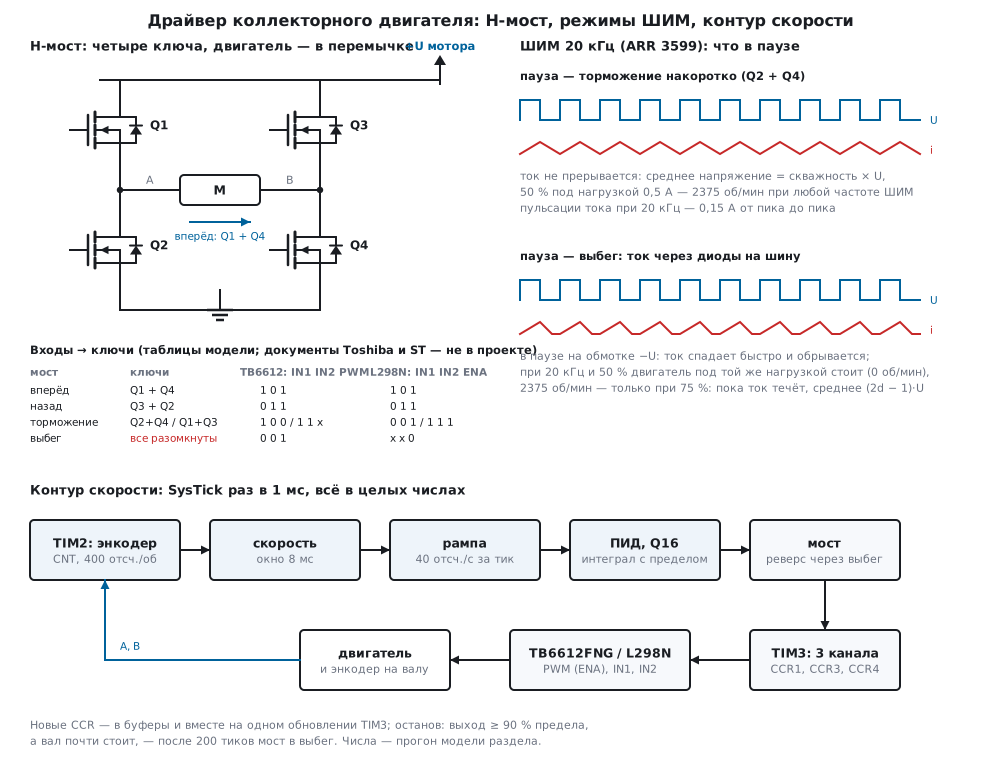
57з.2 L298N and TB6612FNG
Both chips are two H-bridges in one package, each driven by three inputs. They differ in the switches and in how the inputs work.
| L298N | TB6612FNG | |
|---|---|---|
| switches | bipolar transistors | MOSFETs |
| inputs of one bridge | IN1, IN2 and the enable ENA | IN1, IN2 and the PWM input, a common STBY |
| pause on the enable or PWM input | ENA = 0 — coast | PWM = 0 — brake |
| IN1 = IN2 | brake (with ENA = 1) | 1 1 — brake, 0 0 — coast |
| loss in a closed switch | a junction drop, weakly dependent on current | current × channel resistance |
| flyback diodes | the chip has none — modules carry separate ones | present in the MOSFET structure |
| current shunt | SENSE pins to the bridge ground — for your own shunt (57б) | none |
The table is recalled from the ST and Toshiba documents: they are not in the project, and it must be checked against your own document before a board is made. How many volts the L298N switches lose and what resistance the TB6612FNG switches have is not given here for the same reason. Qualitatively the difference is this: on the bipolar L298N the drop across two closed switches hardly depends on current and eats a noticeable share of a low supply, on the MOSFET TB6612FNG it grows with current and is almost zero at low current. The motor gets the rail voltage minus this drop, and its no-load speed falls by the same share.
The main point for the firmware: the same PWM pause on different inputs
means different things. The bridge code dc_pins knows this for both
chips:
void dc_pins(uint8_t chip, uint8_t mode, int32_t duty, uint16_t period, dc_pins_t *o)
{
    uint16_t on = (uint16_t)(duty < 0 ? (duty < -(int32_t)period ? period : -duty)
                                      : (duty > (int32_t)period ? period : duty));
    uint16_t a = duty >= 0 ? period : 0, b = duty < 0 ? period : 0;
    if ((chip == DC_TB6612) == (mode == DC_DRIVE_BRAKE)) {
        o->pwm = on;                                    /* ШИМ на входе PWM (ENA), направление — уровнями */
        o->in1 = a;
        o->in2 = b;
    } else {
        o->pwm = period;                                /* PWM (ENA) всегда «1», ШИМ — на входе направления */
        o->in1 = duty >= 0 ? on : 0;
        o->in2 = duty < 0 ? on : 0;
    }
}
All three pins are channels of one timer, and the value of each is a
CCR: 0 is "0" all the time, period = ARR + 1 is "1" all the time
(RM0008, p. 387), PWM in between. The bench model turns the pins into
bridge states by its own tables of both chips. At a duty of 900 out of
3600 (25 %) forward:
| Chip | Pause | PWM (ENA) | IN1 | IN2 | Bridge over a period |
|---|---|---|---|---|---|
| TB6612FNG | brake | 900 | 3600 | 0 | forward 0.25, brake 0.75 |
| TB6612FNG | coast | 3600 | 900 | 0 | forward 0.25, coast 0.75 |
| L298N | brake | 3600 | 900 | 0 | forward 0.25, brake 0.75 |
| L298N | coast | 900 | 3600 | 0 | forward 0.25, coast 0.75 |
On the TB6612FNG braking in the pause means PWM on the PWM input, on the L298N on the IN input. For all five tested duty values (−3600, −900, 0, 900, 3600) and both modes the bridge of both chips goes through the same states, and the motor speed in the model is the same. A duty of 0 in the brake mode is braking, in the coast mode it is coasting.
57з.3 PWM on a timer: frequency, braking and coasting
On the F103 TIM3 is convenient: PA6, PB0 and PB1 are its channels 1, 3 and 4
(DocID13587, p. 29). TIM3 sits on APB1 but counts from 72 MHz (section 13.3):
PSC = 0, ARR = 3599 give PWM at 20 kHz with 3600 steps. TIM1 also works —
it adds the MOE bit (13.5), and complementary outputs with a dead time
(57а.6) are needed by a bridge of discrete transistors, not by a module.
All three channels use preload (RM0008, p. 386): new CCR values take
effect together on one update, and a direction input cannot switch before
the PWM input.
void SysTick_Handler(void)
{
    dc_pins_t o;
    ms++;
    dc_ctl_tick(&ctl, (uint16_t)TIM2->CNT, &o);
    TIM3->CCR1 = o.pwm;                                 /* все три — в буферы: вступят вместе */
    TIM3->CCR3 = o.in1;                                 /* на одном обновлении TIM3 */
    TIM3->CCR4 = o.in2;
}
PWM frequency. The electrical time constant of the winding is L / R = 0.5 ms, and everything depends on how many PWM periods fit into it. The model: a duty of 50 %, a load of 0.01 N·m (current 0.5 A), 5 s to reach the steady state, averages over the last 0.1 s:
| PWM | PSC, ARR |
Brake: current ripple | Copper loss | Speed | Coast: speed | Coast: average on the winding |
|---|---|---|---|---|---|---|
| 1 kHz | 1, 35 999 | 2.774 A | 3.599 | 2374 rpm | 3348 rpm | 8.05 V |
| 4 kHz | 0, 17 999 | 0.746 A | 1.177 | 2375 rpm | 580 rpm | 2.22 V |
| 20 kHz | 0, 3599 | 0.150 A | 1.007 | 2375 rpm | 0 | 0.29 V |
"Copper loss" is the ratio of the squared RMS current to the squared mean current: how many times more the ripple heats the winding than a direct current of the same mean. At 1 kHz it is 3.6 times, at 20 kHz almost nothing extra. Besides, 1 and 4 kHz are in the middle of the audible range: the winding and the housing whine at the PWM frequency; 20 kHz is at the upper edge of hearing. The price of a high frequency is switching loss in the switches: it grows in proportion to the frequency, and how large it is for the L298N and the TB6612FNG is in documents the project does not have.
Braking in the pause. The current is not interrupted, and the winding gets on average exactly the duty cycle × U: 6.00 V at 50 % at any frequency, and the speed is the same. At no load the speed is proportional to the duty cycle — 570, 1425, 2851, 4276 and 5131 rpm at 10, 25, 50, 75 and 90 %, exactly fractions of the 5701 rpm no-load speed (57а).
Coasting in the pause. While the current flows through the diodes the winding sees −U, and the current falls fast. At 20 kHz it manages to drop to zero within the pause — it is discontinuous, and its average is not enough for the load. Under the same 0.01 N·m load, 20 kHz:
| Duty | Brake, rpm | Coast, rpm | Coast: average on the winding |
|---|---|---|---|
| 10 % | 95 | 0 | 0.01 V |
| 25 % | 950 | 0 | 0.07 V |
| 50 % | 2375 | 0 | 0.29 V |
| 75 % | 3801 | 2375 | 6.00 V |
| 90 % | 4656 | 4086 | 9.60 V |
Up to 50 % in the coast mode the motor does not start. From 75 % the current is no longer interrupted: for part of the period the winding sees +U, for the rest −U, on average (2d − 1)·U — at 75 % the same 6.00 V and the same 2375 rpm that braking gives at 50 %. At a low frequency, on the contrary, coasting drives harder: at 1 kHz the current ends early, the winding is open for the rest of the pause and carries the back EMF — on average 8.05 V instead of 6. In the coast mode the speed depends on the PWM frequency and the load, in the brake mode it does not. A speed controller uses braking in the pause.
57з.4 Encoder: speed from CNT
Encoder mode is section 13.7: TIM2 with SMS = 011 counts both edges of
both channels (RM0008, pp. 391 and 407) and finds the direction itself by
table 85 (p. 392). An encoder of 100 lines on the motor shaft gives 400
counts per revolution. The input uses the filter IC1F = 0011: 8 samples
at 72 MHz (p. 414); a motor encoder produces edges often at high speed,
and the long filter of the knob from 13.10 does not fit here.
Speed is the signed difference of CNT readings, summed over a window of
several controller ticks:
int32_t enc_speed(enc_t *e, uint16_t cnt)
{
    int16_t d = (int16_t)(uint16_t)(cnt - e->last);   /* разность со знаком: переход через 0 не страшен */
    e->last = cnt;
    e->sum += d - e->d[e->k];
    e->d[e->k] = d;
    if (++e->k >= e->win)
        e->k = 0;
    return e->sum * (int32_t)CTL_HZ / e->win;
}
The resolution of such a speed is one count per window: with a 1 ms tick
and a window of one tick it is 1000 counts/s, 150 rpm. The model turns the
shaft at a constant speed for 2 s and watches what enc_speed shows:
| Window | Step | 100 rpm | 300 rpm | 1000 rpm | 3000 rpm |
|---|---|---|---|---|---|
| 1 ms | 150 rpm | 0…150 | 150…450 | 900…1050 | 2850…3150 |
| 8 ms | 18.75 rpm | 93.8…112.5 | 281.2…318.8 | 993.8…1012.5 | 2981.2…3018.8 |
| 32 ms | 4.69 rpm | 98.4…103.0 | 295.2…304.6 | 998.4…1003.0 | 2995.2…3004.7 |
The step is constant, and at low speed it becomes the whole value: with a 1 ms window a speed of 100 rpm is shown as zero or as 150. A long window gives a fine step but lags — a speed over 32 ms trails the real one by about half the window. The section's controller is fine with 8 ms. If you need more precision at low speed, you measure not the number of counts per time but the time between counts — by input capture (13.6); this is not done here.
The signed difference does not notice CNT passing 65 535: 10 s at 3000
rpm is 200 000 counts, three wraps, and not a single tick showed a speed
more than one step away from 20 000 counts/s.
57з.5 Integer speed PID and a ramp
The controller is the one from 47.6, only in CCR steps: the error in
counts per second, coefficients in Q16, the output is a signed duty within
±3600. The derivative is taken from the measurement, but the firmware has
kd = 0: the encoder speed is stepped, and the derivative of steps is
noise (47.4).
int32_t pid57_step(pid57_t *p, int32_t sp, int32_t meas)
{
    int32_t e = sp - meas;
    int64_t pd = (int64_t)p->kp * e - (int64_t)p->kd * (meas - p->prev);
    p->prev = meas;
    int64_t u = (pd + p->integ) / 65536;
    int64_t lim = p->out_max;
    /* насыщение: выход уже в пределе, и ошибка гонит его дальше — интеграл не копим */
    if (!p->aw || !((u >= lim && e > 0) || (u <= -lim && e < 0)))
        p->integ = (int32_t)clamp64((int64_t)p->integ + (int64_t)p->ki * e, p->integ_max);
    return (int32_t)clamp64((pd + p->integ) / 65536, lim);
}
There are two guards against build-up: a limit on the integral itself
(integ_max is the full output) and a ban on accumulating while the output
is at the limit and the error pushes it further. The firmware uses kp = 15000
(0.229 CCR steps per count/s) and ki = 300 per tick. The setpoint moves
to the target along a ramp — no faster than 40 counts/s per tick, which is
40 000 counts/s²: up to 3000 rpm (20 000 counts/s) in 0.5 s.
The run: a target of 3000 rpm with the ramp, after 1 s a load of 0.01 N·m:
| What | Result |
|---|---|
| reached 3000 rpm ± 2 % | after 507 ms (the ramp is 500) |
| overshoot | 2.5 rpm |
| without load | on average 2999.9 rpm, spread 3.8; duty 1895 of 3600 |
| load step | a dip to 2880.4 rpm, back within ± 2 % after 76 ms |
| under load | 2999.7 rpm, spread 7.8; duty 2194 |
| largest current | 0.54 A |
No ramp and no guard. A target of 3000 rpm at once: the controller hits the limit, the motor starts from the full voltage, the current is 5.76 A, nearly the starting current from 57а. With the ban on accumulating in saturation the output stays at the limit for 11 ms and the overshoot is 4.2 rpm (0.1 %); without it — 22 ms at the limit, the integral gathers too much and the overshoot is 52.8 rpm (1.8 %). Closer to the motor's limit the difference is larger: a target of 5000 rpm under load — 43 ms at the limit and 1.8 rpm of overshoot against 159 ms and 56.2 rpm (1.1 %).
Low speed. A target of 100 rpm: with an 8 ms window the shaft speed moves within 3.3 rpm and the duty within 31 steps; with a 32 ms window — 2.6 rpm and 9 steps. The measurement step turns into duty jitter.
The whole controller tick — speed, ramp, PID, protection and bridge:
void dc_ctl_tick(dc_ctl_t *c, uint16_t cnt, dc_pins_t *o)
{
    c->speed = enc_speed(&c->enc, cnt);
    if (c->fault) {
        c->duty = 0;
        dc_state(c->drv.chip, DC_COAST, c->drv.period, o);
        return;
    }
    c->sp = ramp_step(c->sp, c->target, c->accel);
    int32_t u = pid57_step(&c->pid, c->sp, c->speed);
57з.6 Protection: reversal, stall current, regeneration, supply
Reversal. On a sign change dc_drive keeps the bridge coasting for
dead ticks (1 ms in the firmware) so that the current of the previous
direction decays through the diodes. The model shows this does not save
you from a current surge: a motor at 3000 rpm has hardly slowed down in
1 ms, and the reverse voltage adds to its back EMF. A target from +3000
straight to −3000 rpm:
| How | Peak current | Energy from the rail until stop | To zero speed |
|---|---|---|---|
| no ramp, no pause | −8.81 A | +1.885 J | 21 ms |
| no ramp, 1 ms pause | −8.81 A | +1.885 J | 22 ms |
| ramp of 40 counts/s per tick | −0.41 A | −0.381 J | 515 ms |
Without a ramp the reversal current exceeds the starting current (6 A): the
winding gets U plus the back EMF. The pause only shifts the surge by a
millisecond. A dead time is needed for something else — to keep the two
switches of one leg from being on at once; in the L298N and the TB6612FNG
the chip provides it itself (according to documents the project does not
have), and for a bridge of discrete transistors it is the DTG of TIM1
(57а.6). The ramp removes the reversal surge: with it the peak is −0.41 A.
Regeneration. With the ramp the motor is braked by current of the opposite sign, and in the brake-in-pause mode the rail current becomes negative — down to −0.41 A: the motor works as a generator and returns energy. In the model the rail got back 0.381 J of the 0.493 J stored in the rotor at 3000 rpm before the stop; the rest is heat in the winding. Without a ramp it is the other way round: the rail gives another 1.885 J, and all of it turns into heat. Someone must accept the returned energy: a battery will, a power supply with a diode at its output will not, and the voltage on the rail capacitor rises. By how much depends on the capacitance and the source; it was not computed here. A braking ramp, a capacitor at the module and, for big motors, a rail voltage clamp help.
Stall current. The shaft jams — the controller sees an error and raises
the duty to the limit, and the current goes to U / R = 6 A and stays there
until the winding or the driver burns. The protection in dc_ctl_tick: the
output at least 90 % of the limit while the shaft is slower than 30 rpm for
200 ticks in a row — the bridge coasts until a reset.
    int32_t au = u < 0 ? -u : u, as = c->speed < 0 ? -c->speed : c->speed;
    /* выход почти в пределе, а вал стоит: ток останова греет обмотку и ключи — снять питание */
    if (au >= c->pid.out_max * 9 / 10 && as < c->stall_speed) {
        if (++c->stall_n >= c->stall_ms) {
            c->fault = 1;
            c->duty = 0;
            dc_state(c->drv.chip, DC_COAST, c->drv.period, o);
            return;
        }
    } else {
        c->stall_n = 0;
    }
The model jams the shaft at 1000 rpm: the protection trips after 238 ms (the controller needs time to reach 90 %, plus 200 ticks), the current averages 5.63 A during that time, the peak is 6.00 A, then 0. Without the protection, after 0.5 s the duty is 3600 of 3600 and 6.00 A flow continuously. This is protection by speed, not by current: current cannot be limited this way, it is measured with a shunt (57б).
Supply and ground. The driver logic runs from 3.3 or 5 V, the motor from its own rail; the minus of the rail, the minus of the logic and the STM32 ground are joined, otherwise the inputs have no common zero. The pulsed motor current must not flow through the controller ground: the power minus goes to the module by a thick wire, a separate one goes to the controller. A capacitor across the motor rail sits at the module. The allowed input levels and supply voltages are in the document of your chip.
57з.7 Pitfalls
The motor jerks at a low duty or stands still although "PWM is there". The PWM pause landed on the input that gives coasting: on the TB6612FNG that is PWM on IN, on the L298N on ENA. At 20 kHz under a 0.01 N·m load the motor does not start in coast mode up to 50 %. The brake mode is PWM on PWM for the TB6612FNG and on IN for the L298N.
The speed changes with the PWM frequency. The same coasting in the pause: 3348 rpm at 1 kHz and 580 at 4 kHz with the same 50 % duty. With braking in the pause — 2374…2375 at any frequency.
The motor whines. PWM at 1 or 4 kHz is in the middle of the audible
range. 20 kHz (ARR = 3599 at 72 MHz) is at the upper edge of hearing, and
the current ripple is smaller: 0.150 A against 2.774 A at 1 kHz.
The speed jumps between 0 and 150 rpm. The measurement window is one tick: a step of 150 rpm at 400 counts per revolution. An 8 ms window gives a step of 18.75.
After CNT passes 65 535 the speed jumps. The code takes CNT itself
rather than the signed difference (int16_t)(uint16_t)(cnt - last).
A 5 V encoder on PA0, PA1. These pins are not 5 V tolerant (DocID13587,
p. 29): an encoder with 5 V outputs goes to PB6, PB7 (TIM4, 5 V tolerant, p. 32)
or through a divider; an open-collector one — with a pull-up to 3.3 V.
Overshoot after acceleration. The integral built up while the output was at the limit: 52.8 rpm of overshoot against 4.2 with the ban on accumulating in saturation.
The driver trips or heats up on reversal. The target changes in a step: −8.81 A when reversing from 3000 rpm. A coast pause does not help, the ramp does: −0.41 A.
The rail voltage rises during braking. A motor with a ramp returns energy to the source; a power supply with a diode will not accept it. A capacitor, a clamp or a battery.
The shaft jammed — the driver is hot. The controller holds 100 % and 6 A. Protection by speed: the output is at the limit while the shaft stands — coast.
The motor does not turn although everything is set up. The TB6612FNG is
in standby: STBY = 0. Or the grounds of the module and the controller are
not joined.
57з.8 Summary
- H-bridge: forward, reverse, short brake (the winding is shorted), coast (all switches open, current through the diodes to the rail).
- L298N — bipolar switches, ENA = 0 means coast; TB6612FNG — MOSFETs, PWM = 0
means brake, there is
STBY. The same PWM pause on different inputs means different things: the bridge code keeps a table for both. - PWM — three TIM3 channels (PA6, PB0, PB1) with preload,
ARR= 3599 — 20 kHz; current ripple of 0.150 A against 2.774 A at 1 kHz, extra copper loss of 1.007 against 3.599. - Braking in the pause: the average voltage = duty × U, the speed does not depend on the frequency (2375 rpm at 50 %). Coasting in the pause: the current is discontinuous, at 20 kHz under load the motor stands still up to 50 %.
- Encoder on TIM2, 400 counts per revolution: a speed step of 150 rpm with a 1 ms window, 18.75 with an 8 ms window, 4.69 with a 32 ms window.
- PID in Q16 with a ramp of 40 counts/s per tick: 3000 rpm in 507 ms, a dip under load to 2880.4 rpm and 76 ms to recover; the ban on accumulating the integral in saturation — an overshoot of 4.2 rpm instead of 52.8.
- Reversal without a ramp — −8.81 A, a 1 ms pause does not change it; with the ramp −0.41 A, and the rail gets back 0.381 J of 0.493.
- Stalled shaft: 6 A without protection; protection by speed cuts the power after 238 ms.
Full sources
dcdrv57i.h — bridge, encoder, PID and controller: types and prototypes.
/* dcdrv57i.h — раздел 57з: коллекторный двигатель через модуль-драйвер, без регистров.
 * Мост (L298N или TB6612FNG) управляется тремя выводами: два входа направления и вход ШИМ
 * (у L298N — ENA). Все три — каналы одного таймера, значение каждого — CCR: 0 — всегда «0»,
 * period — всегда «1», между ними — ШИМ. Код один для прошивки fw57i.c и стенда host57i.c. */
#ifndef DCDRV57I_H
#define DCDRV57I_H
#include <stdint.h>

#define DC_PERIOD   3600u       /* 72 МГц / 20 кГц: ARR = 3599 */
#define CTL_HZ      1000u       /* регулятор — раз в 1 мс */
#define ENC_CPR     400         /* отсчётов на оборот вала: энкодер 100 штрихов × 4 фронта */
#define ENC_WIN_MAX 32u         /* самое длинное окно измерения скорости, тиков регулятора */
#define RPM(x)      ((int32_t)(x) * ENC_CPR / 60)       /* об/мин → отсчётов в секунду */

enum { DC_COAST = 0, DC_FWD, DC_REV, DC_BRAKE };        /* состояние моста */
enum { DC_TB6612 = 0, DC_L298N };                       /* микросхема */
enum { DC_DRIVE_BRAKE = 0, DC_DRIVE_COAST };            /* что в паузе ШИМ: торможение или выбег */

typedef struct { uint16_t pwm, in1, in2; } dc_pins_t;   /* CCR выводов PWM (ENA), IN1, IN2 */

typedef struct {
    uint8_t chip, mode;
    uint16_t period;            /* ARR + 1 */
    uint16_t dead;              /* тиков в выбеге при смене направления */
    uint16_t wait;              /* сколько ещё ждать */
    int8_t dir;                 /* −1, 0, +1: последнее направление */
} dc_drv_t;

typedef struct {
    uint16_t last;              /* прошлое показание CNT */
    uint8_t win, k;             /* окно и место в кольце */
    int16_t d[ENC_WIN_MAX];     /* приращения за последние win тиков */
    int32_t sum;
} enc_t;

typedef struct {
    int32_t kp, ki, kd;         /* Q16: шагов CCR на (отсчёт/с) */
    int32_t integ, integ_max;   /* Q16, накопитель и его предел */
    int32_t prev;               /* прошлое измерение: производная — по нему */
    int32_t out_max;            /* предел выхода: ±period */
    uint8_t aw;                 /* 1 — не копить интеграл, пока выход в пределе */
} pid57_t;

typedef struct {
    dc_drv_t drv;
    enc_t enc;
    pid57_t pid;
    int32_t target, sp, accel;  /* цель, задание после рампы, шаг рампы за тик (отсчётов/с) */
    int32_t speed, duty;        /* измерено и подано */
    int32_t stall_speed;        /* «стоит», если медленнее, отсчётов/с */
    uint16_t stall_ms, stall_n; /* сколько тиков подряд терпеть и сколько уже */
    uint8_t fault;              /* 1 — останов: мост в выбеге до сброса */
} dc_ctl_t;

void dc_state(uint8_t chip, uint8_t st, uint16_t period, dc_pins_t *o);
void dc_pins(uint8_t chip, uint8_t mode, int32_t duty, uint16_t period, dc_pins_t *o);
int32_t dc_drive(dc_drv_t *d, int32_t duty, dc_pins_t *o);
void enc_init(enc_t *e, uint8_t win, uint16_t cnt);
int32_t enc_speed(enc_t *e, uint16_t cnt);
int32_t pid57_step(pid57_t *p, int32_t sp, int32_t meas);
int32_t ramp_step(int32_t sp, int32_t target, int32_t step);
void dc_ctl_tick(dc_ctl_t *c, uint16_t cnt, dc_pins_t *o);

#endif
dcdrv57i.c — bridge, encoder speed, PID, ramp and protection code, shared by the firmware and the bench.
/* dcdrv57i.c — раздел 57з: мост, энкодер, рампа и ПИД скорости на целых числах. */
#include "dcdrv57i.h"

/* Мост стоит: выбег — все ключи разомкнуты, торможение — обмотка замкнута накоротко. */
void dc_state(uint8_t chip, uint8_t st, uint16_t period, dc_pins_t *o)
{
    if (chip == DC_L298N) {
        o->pwm = st == DC_BRAKE ? period : 0;          /* ENA = 0 — выбег; ENA = 1, IN1 = IN2 — торможение */
        o->in1 = o->in2 = 0;
    } else {
        o->pwm = period;                                /* TB6612: IN1 = IN2 = 0 — выбег, IN1 = IN2 = 1 — торможение */
        o->in1 = o->in2 = st == DC_BRAKE ? period : 0;
    }
}

/* Скважность со знаком: duty = ±period — полное напряжение, 0 — пауза всё время.
 * В паузе ШИМ мост тормозит (DC_DRIVE_BRAKE) или выбегает (DC_DRIVE_COAST). У TB6612 пауза на входе
 * PWM — торможение, на входе IN — выбег; у L298N наоборот: пауза на ENA — выбег, на IN — торможение. */
void dc_pins(uint8_t chip, uint8_t mode, int32_t duty, uint16_t period, dc_pins_t *o)
{
    uint16_t on = (uint16_t)(duty < 0 ? (duty < -(int32_t)period ? period : -duty)
                                      : (duty > (int32_t)period ? period : duty));
    uint16_t a = duty >= 0 ? period : 0, b = duty < 0 ? period : 0;
    if ((chip == DC_TB6612) == (mode == DC_DRIVE_BRAKE)) {
        o->pwm = on;                                    /* ШИМ на входе PWM (ENA), направление — уровнями */
        o->in1 = a;
        o->in2 = b;
    } else {
        o->pwm = period;                                /* PWM (ENA) всегда «1», ШИМ — на входе направления */
        o->in1 = duty >= 0 ? on : 0;
        o->in2 = duty < 0 ? on : 0;
    }
}

/* Смена знака — через выбег на d->dead тиков: ток прошлого направления спадает через диоды,
 * а не встречает сразу противоположную диагональ. Возвращает поданную скважность. */
int32_t dc_drive(dc_drv_t *d, int32_t duty, dc_pins_t *o)
{
    int8_t s = (int8_t)(duty > 0 ? 1 : duty < 0 ? -1 : 0);
    if (s != 0 && d->dir != 0 && s != d->dir) {
        d->wait = d->dead;
        d->dir = 0;
    }
    if (d->wait) {
        d->wait--;
        dc_state(d->chip, DC_COAST, d->period, o);
        return 0;
    }
    if (s != 0)
        d->dir = s;
    dc_pins(d->chip, d->mode, duty, d->period, o);
    return duty;
}

void enc_init(enc_t *e, uint8_t win, uint16_t cnt)
{
    e->last = cnt;
    e->win = win < 1u ? 1u : win > ENC_WIN_MAX ? ENC_WIN_MAX : win;
    e->k = 0;
    e->sum = 0;
    for (unsigned i = 0; i < ENC_WIN_MAX; i++)
        e->d[i] = 0;
}

/* Скорость в отсчётах в секунду: сумма приращений за окно из win тиков. */
int32_t enc_speed(enc_t *e, uint16_t cnt)
{
    int16_t d = (int16_t)(uint16_t)(cnt - e->last);   /* разность со знаком: переход через 0 не страшен */
    e->last = cnt;
    e->sum += d - e->d[e->k];
    e->d[e->k] = d;
    if (++e->k >= e->win)
        e->k = 0;
    return e->sum * (int32_t)CTL_HZ / e->win;
}

static int64_t clamp64(int64_t x, int64_t lim)
{
    return x > lim ? lim : x < -lim ? -lim : x;
}

/* ПИД на Q16 (раздел 47.6): интеграл со своим пределом, производная по измерению, выход — в шагах CCR. */
int32_t pid57_step(pid57_t *p, int32_t sp, int32_t meas)
{
    int32_t e = sp - meas;
    int64_t pd = (int64_t)p->kp * e - (int64_t)p->kd * (meas - p->prev);
    p->prev = meas;
    int64_t u = (pd + p->integ) / 65536;
    int64_t lim = p->out_max;
    /* насыщение: выход уже в пределе, и ошибка гонит его дальше — интеграл не копим */
    if (!p->aw || !((u >= lim && e > 0) || (u <= -lim && e < 0)))
        p->integ = (int32_t)clamp64((int64_t)p->integ + (int64_t)p->ki * e, p->integ_max);
    return (int32_t)clamp64((pd + p->integ) / 65536, lim);
}

/* Рампа: задание идёт к цели не быстрее step за тик. */
int32_t ramp_step(int32_t sp, int32_t target, int32_t step)
{
    if (target > sp + step)
        return sp + step;
    if (target < sp - step)
        return sp - step;
    return target;
}

/* Тик регулятора раз в 1 мс: скорость по энкодеру, рампа, ПИД, защита от останова, мост. */
void dc_ctl_tick(dc_ctl_t *c, uint16_t cnt, dc_pins_t *o)
{
    c->speed = enc_speed(&c->enc, cnt);
    if (c->fault) {
        c->duty = 0;
        dc_state(c->drv.chip, DC_COAST, c->drv.period, o);
        return;
    }
    c->sp = ramp_step(c->sp, c->target, c->accel);
    int32_t u = pid57_step(&c->pid, c->sp, c->speed);
    int32_t au = u < 0 ? -u : u, as = c->speed < 0 ? -c->speed : c->speed;
    /* выход почти в пределе, а вал стоит: ток останова греет обмотку и ключи — снять питание */
    if (au >= c->pid.out_max * 9 / 10 && as < c->stall_speed) {
        if (++c->stall_n >= c->stall_ms) {
            c->fault = 1;
            c->duty = 0;
            dc_state(c->drv.chip, DC_COAST, c->drv.period, o);
            return;
        }
    } else {
        c->stall_n = 0;
    }
    c->duty = dc_drive(&c->drv, u, o);
}
fw57i.c — STM32F103 firmware: TIM3 drives the three driver inputs, TIM2 reads the encoder, the controller runs in SysTick.
/* fw57i.c — раздел 57з: коллекторный двигатель через TB6612FNG (или L298N) на STM32F103 (BluePill), 72 МГц.
 * TIM3 — ШИМ 20 кГц на трёх каналах: PA6 (CH1) — PWMA (у L298N — ENA), PB0 (CH3) — AIN1 (IN1), PB1 (CH4) — AIN2 (IN2).
 * TIM2 — энкодер на PA0, PA1, счёт по обоим фронтам. PB12 — STBY у TB6612 (у L298N не нужен).
 * SysTick раз в 1 мс: скорость, рампа, ПИД, защита от останова (dcdrv57i.c), новые CCR — с ближайшего обновления.
 * Тактирование до 72 МГц — как в разделе 6; TIM2 и TIM3 на APB1 (36 МГц) считают от 72 МГц (раздел 13.3). */
#include "stm32f10x.h"
#include "dcdrv57i.h"

#define CPU_HZ   72000000u
#define DRV_CHIP DC_TB6612
#define DRV_MODE DC_DRIVE_BRAKE

_Static_assert(CPU_HZ / DC_PERIOD == 20000u, "ШИМ 20 кГц: ARR = 3599");

static dc_ctl_t ctl;
static volatile uint32_t ms;

void SysTick_Handler(void)
{
    dc_pins_t o;
    ms++;
    dc_ctl_tick(&ctl, (uint16_t)TIM2->CNT, &o);
    TIM3->CCR1 = o.pwm;                                 /* все три — в буферы: вступят вместе */
    TIM3->CCR3 = o.in1;                                 /* на одном обновлении TIM3 */
    TIM3->CCR4 = o.in2;
}

static void pwm_init(void)
{
    GPIOA->CRL = (GPIOA->CRL & ~(0xFu << 24)) | 0xBu << 24;    /* PA6 — TIM3_CH1, push-pull */
    GPIOB->CRL = (GPIOB->CRL & ~0xFFu) | 0xBBu;                /* PB0, PB1 — TIM3_CH3, TIM3_CH4 */
    TIM3->PSC = 0;
    TIM3->ARR = DC_PERIOD - 1u;
    TIM3->CCMR1 = TIM_CCMR1_OC1M_2 | TIM_CCMR1_OC1M_1 | TIM_CCMR1_OC1PE;      /* ШИМ 1, буфер */
    TIM3->CCMR2 = TIM_CCMR2_OC3M_2 | TIM_CCMR2_OC3M_1 | TIM_CCMR2_OC3PE
                | TIM_CCMR2_OC4M_2 | TIM_CCMR2_OC4M_1 | TIM_CCMR2_OC4PE;
    TIM3->CCER = TIM_CCER_CC1E | TIM_CCER_CC3E | TIM_CCER_CC4E;
    dc_pins_t o;
    dc_state(DRV_CHIP, DC_COAST, DC_PERIOD, &o);        /* до первого тика — выбег */
    TIM3->CCR1 = o.pwm;
    TIM3->CCR3 = o.in1;
    TIM3->CCR4 = o.in2;
    TIM3->CR1 = TIM_CR1_ARPE;
    TIM3->EGR = TIM_EGR_UG;
    TIM3->CR1 |= TIM_CR1_CEN;
}

static void enc_tim_init(void)
{
    /* PA0, PA1 — входы с подтяжкой вверх: у энкодера с открытым коллектором своей нет */
    GPIOA->CRL = (GPIOA->CRL & ~0xFFu) | 0x88u;
    GPIOA->BSRR = GPIO_BSRR_BS0 | GPIO_BSRR_BS1;
    TIM2->CCMR1 = TIM_CCMR1_CC1S_0 | TIM_CCMR1_CC2S_0                        /* TI1, TI2 — входы */
                | TIM_CCMR1_IC1F_1 | TIM_CCMR1_IC1F_0 | TIM_CCMR1_IC2F_1 | TIM_CCMR1_IC2F_0;   /* 0011: N = 8 */
    TIM2->SMCR = TIM_SMCR_SMS_1 | TIM_SMCR_SMS_0;       /* 011: энкодер, оба фронта обоих каналов */
    TIM2->ARR = 0xFFFFu;
    TIM2->CR1 = TIM_CR1_CEN;
}

int main(void)
{
    RCC->APB2ENR |= RCC_APB2ENR_IOPAEN | RCC_APB2ENR_IOPBEN | RCC_APB2ENR_IOPCEN;
    RCC->APB1ENR |= RCC_APB1ENR_TIM2EN | RCC_APB1ENR_TIM3EN;
    GPIOB->CRH = (GPIOB->CRH & ~(0xFu << 16)) | 0x2u << 16;    /* PB12 — STBY */
    GPIOC->CRH = (GPIOC->CRH & ~(0xFu << 20)) | 0x2u << 20;    /* PC13 — светодиод платы */
    pwm_init();
    enc_tim_init();

    ctl.drv = (dc_drv_t){DRV_CHIP, DRV_MODE, DC_PERIOD, 1u, 0u, 0};
    enc_init(&ctl.enc, 8u, (uint16_t)TIM2->CNT);
    ctl.pid = (pid57_t){15000, 300, 0, 0, 3600 << 16, 0, DC_PERIOD, 1u};
    ctl.accel = 40;                                     /* 40 отсчётов/с за 1 мс: 0 → 3000 об/мин за 0,5 с */
    ctl.stall_speed = RPM(30);
    ctl.stall_ms = 200u;
    ctl.target = RPM(1500);
    GPIOB->BSRR = GPIO_BSRR_BS12;                       /* TB6612 из дежурного режима */
    SysTick_Config(CPU_HZ / CTL_HZ);

    uint32_t next = 0;
    for (;;) {
        if ((int32_t)(ms - next) >= 0) {
            next += 3000u;                              /* каждые 3 с — реверс: +1500 ↔ −1500 об/мин */
            __disable_irq();
            ctl.target = -ctl.target;
            __enable_irq();
        }
        GPIOC->BSRR = ctl.fault ? GPIO_BSRR_BR13 : GPIO_BSRR_BS13;   /* светодиод горит — останов */
    }
}
Next: section 57и "AS5600 magnetic encoder: angle over I2C and PWM, zero position, turn counting and speed" — from counting increments to an absolute angle: a magnet on the shaft, Hall sensors over I2C and turns without losing the zero.