 Embedded HandbookApps
57и. AS5600 magnetic encoder: angle over I2C and PWM, zero position, turn counting and speed
In 57з the motor speed was measured by an incremental encoder on TIM2: 400
counts per revolution, the CNT counter running from power-up. It knows
how far the shaft has turned but not where the shaft is: after a reset the
zero is lost and has to be found with a limit switch or an index mark. The
AS5600 magnetic sensor is a different kind: a chip under the shaft, a
magnet on the shaft, and the angle within a turn is known right after
power-up, 12 bits.
What is inside: how Hall sensors see an angle and why a uniform stray
field does not disturb them; how to connect the AS5600 to an STM32F103 and
read the angle over I2C; how to check that the magnet is in place and the
air gap is right; how to take the angle from the PWM output by capture on a
timer without knowing the frequency of the sensor oscillator; where to put
the zero — in your program or in the ZPOS register — and why there is no
need to burn it; how to count turns and up to what speed that works; where
the speed comes from as a difference of angles and how to filter it; what
hysteresis, a magnet off the axis and a correction table do.
Sources: RM0008 (DocID13902 Rev 17): PWM input mode, p. 384; the TS and
SMS fields (101 is TI1FP1, 100 is reset), p. 407; reception of one and
two bytes by an I2C master, p. 764. DocID13587 Rev 17 (STM32F103x8/xB): PA0 is
TIM2_CH1_ETR without 5 V tolerance, p. 29; PA8 is TIM1_CH1 with 5 V tolerance,
p. 31; PB6, PB7 are I2C1_SCL, I2C1_SDA with 5 V tolerance, p. 32. The
project has no AS5600 document. Part of the facts is checked against two
open projects on disk: the Zephyr 4.4.2 driver drivers/sensor/ams/ams_as5600/ams_as5600.c
— registers RAW ANGLE 0x0C, ANGLE 0x0E, STATUS 0x0B, bits MD, ML, MH at
5, 4, 3, 4096 counts per revolution; SimpleFOC 2.4.0 MagneticSensorI2C.cpp —
address 0x36, angle at 0x0C, 12 bits, high byte mask 0x0F;
MagneticSensorPWM.h — PWM at 115, 230, 460 or 920 Hz, a frame of 4351 clocks,
zero at 128 clocks, the largest value at 4223. The rest — ZPOS 0x01, CONF 0x07,
AGC 0x1A, MAGNITUDE 0x1B, BURN 0xFF and the CONF fields — follows the
manufacturer documentation and is not verified here. All numbers below come
from a run of the driver _verify/mag57j/mag57j.c on a computer (gcc 12.2.0)
with its own model of the AS5600 as an I2C slave in Python 3.11: the magnet,
field, noise, offset, PWM output and TIM2 in it are nominal; the firmware is
built by armclang 6.24 for the
Cortex-M3.
What it is called in the documentation
Original Meaning contactless magnetic rotary position sensor contactless magnetic angle sensor diametrically magnetized magnet magnet magnetized across its diameter Hall element Hall sensor raw angle, angle angle without corrections, angle from the zero position zero position ( ZPOS), maximum position (MPOS)zero position, end position magnet detected ( MD), too weak (ML), too strong (MH)magnet present, field weak, field strong automatic gain control ( AGC)automatic gain adjustment hysteresis ( HYST)output hysteresis slow filter, fast filter threshold ( SF,FTH)slow filter, threshold of the fast one output stage ( OUTS), PWM frequency (PWMF)output kind, PWM frequency permanent programming ( BURN)burning into non-volatile memory, irreversible PWM input mode timer PWM input mode absolute, incremental encoder absolute, incremental encoder eccentricity, misalignment magnet off the sensor axis
57и.1 Principle: a magnet, Hall sensors, 12 bits per revolution
On the end of the shaft sits a small round magnet magnetized across its
diameter: one half is north, the other south. Under it, on the axis, is the
AS5600. Inside the chip, Hall sensors measure the field perpendicular to the
die at several points around a circle. The difference of opposite points
gives two components X and Y, the angle is atan2(Y, X), and that is 12
bits: 4096 counts per revolution, 0.0879° per count.
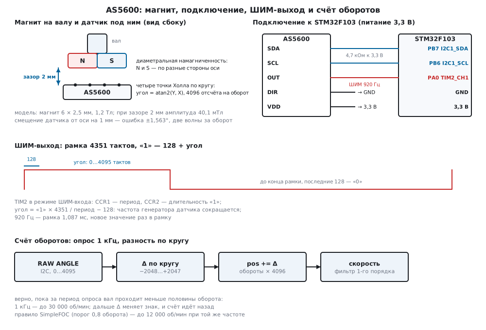
The difference of points is not decoration. A uniform stray field (the Earth's, a distant neighbouring motor) adds to all points equally and cancels. In the section model 5 mT of uniform field shifted the angle by exactly 0 counts. A non-uniform field — a steel screw nearby, the magnet of a neighbouring shaft — does not cancel that way; the model does not compute it.
The model: a magnet of 6 × 2.5 mm with a remanence of 1.2 T, four points on a
circle of radius 1 mm, the field as an integral over magnetic charges on the
magnet surface. The status thresholds and the AGC law in the model are
nominal: there is no document, and the real thresholds are different. How
the picture changes with the gap:
| Gap | Amplitude | STATUS |
AGC |
MAGNITUDE |
Angle noise |
|---|---|---|---|---|---|
| 0.5 mm | 65.3 mT | MD, MH | 0 | 2137 | 0.31 counts |
| 1.0 mm | 60.3 mT | MD, MH | 0 | 1973 | 0.33 counts |
| 1.5 mm | 50.5 mT | MD | 14 | 1800 | 0.40 counts |
| 2.0 mm | 40.1 mT | MD | 53 | 1800 | 0.50 counts |
| 3.0 mm | 23.5 mT | MD | 142 | 1800 | 0.85 counts |
| 4.0 mm | 13.7 mT | MD | 233 | 1800 | 1.46 counts |
| 6.0 mm | 5.1 mT | MD, ML | 255 | 764 | 3.93 counts |
| 8.0 mm | 2.2 mT | ML | 255 | 331 | 9.07 counts |
The field falls fast with the gap: from 1 to 4 mm by a factor of 4.4. The
automatic gain keeps MAGNITUDE constant while there is gain to spare, and
AGC shows how much of it is used: the number grows with the gap. The
angle noise in the model is inversely proportional to the field — at a 6 mm
gap it is 7.9 times larger than at 2 mm.
How the AS5600 differs from the encoder of 57з:
| Incremental encoder (57з) | AS5600 | |
|---|---|---|
| what it knows | the increment since power-up | the angle within a turn at once |
| zero | found with a limit switch or a mark | always there, shifted by the program or ZPOS |
| resolution | 400 counts per revolution | 4096 counts per revolution |
| who counts | the timer CNT, no processor |
the processor reads the angle and counts turns itself |
| speed limit | edge rate and input filter | half a turn per polling period (57и.5) |
| mechanics | disc or lines | magnet on the shaft end, contactless |
57и.2 Connection to the F103 and the angle over I2C
I2C1 is PB6 (SCL) and PB7 (SDA), both 5 V tolerant (DocID13587, p. 32),
open drain, 400 kHz, pull-ups of 4.7 kΩ to the sensor supply. The address is 0x36
(as in SimpleFOC), and there is only one: two AS5600 cannot share a bus — the
second goes to I2C2 or behind a bus switch. The DIR pin sets which way the
angle grows — it is tied to ground or to the supply, never left floating. The
OUT pin is an analog or PWM output (57и.3). Supply is 3.3 or
5 V; how to connect the supply pins in each case is in the manufacturer
document and not verified here.
The angle is two bytes, high byte first, 12 significant bits. The driver writes the register number, makes a repeated start and reads two bytes:
/* Двухбайтовый регистр: старший байт первым, значащих бит 12. */
int as_read12(uint8_t reg, uint16_t *v)
{
uint8_t b[2];
if (as_port_xfer(AS_ADDR, ®, 1u, b, 2u))
return AS_E_BUS;
*v = (uint16_t)((b[0] & 0x0Fu) << 8 | b[1]);
return AS_OK;
}
The mask 0x0F is as in SimpleFOC; Zephyr takes both bytes whole
(sys_get_be16), without a mask. The port as_port_xfer in the firmware is I2C1 per
RM0008, p. 764: for two bytes POS and ACK are set before the address, for one
ACK is cleared before clearing ADDR (17.4). At 400 kHz an angle read takes
120.0 µs of bus time, one byte 97.5 µs; polling every 1 ms uses 12.0 % of the bus.
Conversion to degrees — in integers, in hundredths of a degree with rounding:
(raw × 36000 + 2048) / 4096.
RAW ANGLE |
0 | 1 | 2 | 3 | 512 | 1024 | 2048 | 3071 | 4095 |
|---|---|---|---|---|---|---|---|---|---|
| hundredths of a degree | 0 | 9 | 18 | 26 | 4500 | 9000 | 18000 | 26991 | 35991 |
The model turns the shaft in 30° steps and reads RAW ANGLE: shaft at 0° gives 2470
counts (217.09°), shaft at 90° gives 3493 (307.00°). The constant shift of 217° is how
the magnet is glued to the shaft (37° in the model) plus the 180° by which the
diametric pair is turned; the scatter around the computed angle is from −1 to 1 count.
Hence the need for a zero position (57и.4).
Is the magnet in place? Before work the driver reads STATUS, AGC and
MAGNITUDE — three transfers, 315.0 µs:
/* Магнит на месте? STATUS, AGC и MAGNITUDE; ошибка — если MD = 0 или усиление в пределе. */
int as_magnet(as_mag_t *m)
{
    if (as_read8(AS_STATUS, &m->status) || as_read8(AS_AGC, &m->agc) || as_read12(AS_MAGNITUDE, &m->magnitude))
        return AS_E_BUS;
    if (!(m->status & AS_MD))
        return AS_E_NOMAG;
    if (m->status & AS_ML)
        return AS_E_WEAK;
    if (m->status & AS_MH)
        return AS_E_STRONG;
    return AS_OK;
}
Zephyr makes the same check before every angle read and with MD = 0, ML
or MH does not update the angle. In the model without a magnet: ML without MD, AGC 255,
MAGNITUDE 0. An axially magnetized magnet instead of a diametric one at a 0.25 mm offset
gives a field of 5.0 mT, MD and ML, and, most importantly, the angle over a 360° turn
of the shaft moves within only 18 counts: the field of an axial magnet does not
change with rotation, the sensor sees noise and offset, not the shaft. In the firmware, until
as_magnet returns AS_OK, the board LED is on.
57и.3 PWM output: the angle by capture on a timer
If the I2C wires are long or the bus is busy, the angle is taken from the OUT pin in
PWM mode. The frame is 4351 clocks of the sensor oscillator: 128 clocks of "1", then
the angle — 0…4095 clocks of "1", the rest "0", the last 128 clocks always "0".
The frame rate is 115, 230, 460 or 920 Hz set by the PWMF field; the sensor has
its own oscillator, and the firmware does not know its exact frequency.
Hence the method: measure both the period and the time at "1", and take the angle from their ratio — the frequency cancels. TIM2 in PWM input mode does both measurements itself (RM0008, p. 384): channel 1 catches the rising edge and resets the counter, channel 2 the falling edge:
static void pwm_in_init(void)
{
    RCC->APB1ENR |= RCC_APB1ENR_TIM2EN;
    GPIOA->CRL = (GPIOA->CRL & ~0xFu) | 0x4u;           /* PA0 — плавающий вход: выход датчика двухтактный */
    TIM2->PSC = 1u;
    TIM2->ARR = 0xFFFFu;
    TIM2->CCMR1 = TIM_CCMR1_CC1S_0 | TIM_CCMR1_CC2S_1;  /* CC1S = 01: TI1; CC2S = 10: тоже TI1 */
    TIM2->CCER = TIM_CCER_CC1E | TIM_CCER_CC2E | TIM_CCER_CC2P;   /* IC2 — по спаду */
    TIM2->SMCR = TIM_SMCR_TS_2 | TIM_SMCR_TS_0          /* TS = 101: TI1FP1 */
               | TIM_SMCR_SMS_2;                        /* SMS = 100: сброс счётчика по фронту */
    TIM2->DIER = TIM_DIER_CC1IE;
    TIM2->EGR = TIM_EGR_UG;
    TIM2->CR1 = TIM_CR1_CEN;
    NVIC_EnableIRQ(TIM2_IRQn);
}
Conversion to an angle — in integers, with rounding and with limits of 0 and 4095:
uint16_t as_pwm_raw(uint32_t period, uint32_t high)
{
    if (period == 0u)
        return 0u;
    uint32_t clk = (uint32_t)(((uint64_t)high * AS_PWM_FRAME + period / 2u) / period);
    if (clk <= AS_PWM_HEAD)
        return 0u;
    clk -= AS_PWM_HEAD;
    return (uint16_t)(clk > AS_CPR - 1 ? AS_CPR - 1 : clk);
}
PSC is chosen so that the period fits the 16 bits of CCR1 and a frame clock
spans several ticks. The model takes 52 angles in 7° steps, a random tick
phase, and compares with the sensor ANGLE; "drift" means the sensor oscillator runs
3 % fast:
| PWM | PSC |
Frame | Ticks per clock | Error | Drift 3 %: error | Drift 3 %, period taken as known |
|---|---|---|---|---|---|---|
| 115 Hz | 15 | 8.696 ms | 8.99 | 0 | 0 | 122 counts |
| 230 Hz | 7 | 4.348 ms | 8.99 | 0 | 0 | 122 counts |
| 460 Hz | 3 | 2.174 ms | 8.99 | 0 | 0 | 122 counts |
| 920 Hz | 1 | 1.087 ms | 8.99 | 0 | 0 | 122 counts |
Nine ticks per clock are enough for no angle to differ from ANGLE.
If only the time at "1" is measured and divided by a computed clock, an oscillator
drift of 3 % gives up to 122 counts of error — 10.7°. This is how
MagneticSensorPWM in SimpleFOC works: the pulse length in microseconds and a
frequency given as a number at construction. At the edges: 128 clocks of "1" or less give
0, 129 gives 1, 4223 and more give 4095.
The price of the PWM output is the update rate: one value per frame, 1.087 ms at
920 Hz and 8.696 ms at 115. The firmware sets 920 Hz and PSC = 1. The sensor output
follows its supply: at 3.3 V — to PA0 (TIM2_CH1, without 5 V tolerance,
DocID13587, p. 29), at 5 V — to PA8 (TIM1_CH1, 5 V tolerant, p. 31)
or through a divider.
57и.4 Zero position: in the program or through ZPOS, without burning
The zero is set in two ways. In the program: the firmware remembers the
RAW ANGLE reading at the zero position and subtracts it: (raw − zero) & 4095. In the
sensor: write that reading to ZPOS, and the ANGLE register (0x0E) itself
returns the angle from zero, and so does the PWM output.
/* Ноль там, где вал стоит сейчас: ZPOS = RAW ANGLE. Только запись в регистр — без BURN:
 * после выключения питания ZPOS снова 0, и прошивка пишет его при каждом старте. */
int as_set_zpos(uint16_t *zpos)
{
    uint16_t raw, back;
    if (as_read12(AS_RAW_ANGLE, &raw) || as_write12(AS_ZPOS, raw) || as_read12(AS_ZPOS, &back))
        return AS_E_BUS;
    *zpos = back;
    return back == raw ? AS_OK : AS_E_BUS;
}
The run: shaft at 100°, RAW ANGLE 3608, as_set_zpos wrote 3606 (noise
between reads), ANGLE five times in a row — 1, 1, 0, 0, 0. Shaft at 190°:
ANGLE 1024 — exactly 90.00°, the program zero on the same read — 1023.
Both ways give the same; ZPOS is needed when the angle is read from the PWM output
or when there is nobody to subtract.
After power-off ZPOS in the model is 0 again, and ANGLE equals RAW
ANGLE (534 and 535). To make the zero survive power-off, the document has the
BURN command (a write to 0xFF): it burns ZPOS and MPOS into
non-volatile memory. This is irreversible and allowed a limited number of
times — per the manufacturer documentation. There is no need for it: the
firmware writes the zero from its own memory to ZPOS at every start (in fw57j.c —
ZERO_RAW), and a spoiled burn cannot happen. The driver has no burn function,
and during the whole run the model received not a single write to 0xFF.
57и.5 Turns and speed
The AS5600 knows the angle within a turn; the firmware counts the turns. Between two polls it takes the difference of the angles around the circle — within −2048…+2047 — and adds it to the full angle:
/* Разность двух углов по кругу: −2048…+2047. */
int16_t as_wrap(int32_t d)
{
d &= AS_CPR - 1;
return (int16_t)(d >= AS_CPR / 2 ? d - AS_CPR : d);
}
/* Развёртка: верно, пока за период опроса вал проходит меньше половины оборота. */
int32_t as_turns_step(as_turns_t *t, uint16_t raw)
{
int16_t d = as_wrap((int32_t)raw - t->last);
t->last = raw;
t->pos += d;
return d;
}
The polling rate limit. The wrapped difference cannot tell a turn by Δ from a
turn by Δ − 4096: it picks the one smaller in magnitude. So the count is correct
while the shaft moves less than half a turn per polling period: at a polling
rate f — up to 30·f rpm. At 1 kHz that is 30 000 rpm, at 100 Hz 3000.
The run — 1 s of rotation, the driver reads RAW ANGLE over I2C every tick:
| Polling | Shaft | Step per poll | Expected | Counted |
|---|---|---|---|---|
| 1 kHz | 600 rpm | 41.0 counts | 10.00 rev | 10.00 rev |
| 1 kHz | −6000 rpm | −409.6 counts | −100.00 rev | −100.00 rev |
| 1 kHz | 29 000 rpm | 1979.7 counts | 483.33 rev | 483.33 rev |
| 1 kHz | 29 900 rpm | 2041.2 counts | 498.33 rev | 498.33 rev |
| 1 kHz | 30 100 rpm | 2054.8 counts | 501.67 rev | −498.33 rev |
| 1 kHz | 31 000 rpm | 2116.3 counts | 516.67 rev | −483.33 rev |
| 100 Hz | 2900 rpm | 1979.7 counts | 48.33 rev | 48.33 rev |
| 100 Hz | 3100 rpm | 2116.3 counts | 51.67 rev | −48.33 rev |
Beyond the limit the count is not slightly off — it runs backwards: every step
larger than 2048 counts is taken as a step the other way. The model
does not account for the sensor itself lagging at such speeds because of its filter —
one more reason to keep a margin. SimpleFOC (Sensor::update) counts a
zero crossing if the jump is larger than 0.8 of a turn; the same analysis gives a
limit of 0.2 of a turn per poll: at 1 kHz 11 900 rpm counts correctly (198.33
rev), 12 100 does not (0.67 rev instead of 201.67).
The full angle pos is an int32_t in counts: it lasts for 524 288 turns,
at 6000 rpm for 87 minutes; then it overflows, and a long-running
shaft needs a 64-bit count or a reset. DIR pulled to the supply flips the sign:
600 rpm are counted as −10.00 rev.
Speed is the difference over a polling period, in counts per second, with a first-order filter:
/* Скорость из приращения за период опроса, фильтр первого порядка; отсчётов/с. */
int32_t as_speed_step(as_speed_t *s, int32_t delta)
{
int32_t x = delta * (int32_t)s->hz * 256;
s->y += (x - s->y) / (1 << s->k);
return s->y / 256;
}
Without a filter the speed step is one count per 1 ms: 14.65 rpm versus 150 for the 400-count encoder of 57з. But the AS5600 has noise on every count, and that noise is divided by the polling period. The model: a 2 mm gap (noise 0.5 counts), polling at 1 kHz; the shaft stands, then at 0.1 s the speed jumps to 600 rpm; "scatter" is from the smallest to the largest value over the last 0.5 s:
Filter k |
Standing: scatter | 600 rpm: mean | 600 rpm: scatter | To 90 % |
|---|---|---|---|---|
| 0 (no filter) | 73.2 rpm | 600.0 | 73.2 rpm | 1 ms |
| 3 | 6.0 rpm | 600.0 | 6.7 rpm | 18 ms |
| 5 | 1.5 rpm | 600.0 | 1.7 rpm | 73 ms |
| 7 | 0.3 rpm | 593.5 | 25.4 rpm | 294 ms |
Every step of k makes the filter twice as long: noise drops, lag grows. At
k = 7 the speed has not reached 600 within 0.4 s after the jump — hence both the
mean of 593.5 and the large scatter. The firmware uses k = 5.
57и.6 Noise, hysteresis, magnet offset and a correction table
Noise. At a 2 mm gap the model noise has a standard deviation of 0.497 counts — 0.0437°.
A still shaft between two counts gives a RAW ANGLE that jumps.
The HYST hysteresis in CONF (per the documentation 0…3 counts; the model
repeats that rather than checks it) holds ANGLE and the PWM output in place until the
new angle moves past the threshold. The shaft stands exactly halfway between two
counts, 1000 reads:
HYST |
ANGLE: span |
ANGLE: value changes |
RAW ANGLE: span |
|---|---|---|---|
| 0 | 3 | 559 | 3 |
| 1 | 3 | 63 | 3 |
| 2 | 0 | 0 | 3 |
| 3 | 0 | 0 | 3 |
RAW ANGLE knows no hysteresis — it is for counting turns and speed. The price of
hysteresis is a dead band: a turn smaller than the threshold does not show on the output.
The sensor filters SF and FTH (a slow filter and the threshold after which the
fast one takes over) are not reproduced by the model: their times are in the manufacturer
document.
Magnet off the axis. If the shaft axis passes beside the centre of the sensor, the field at the Hall points changes not only with rotation. In the model an offset of the sensor from the shaft axis gives an error that looks like a sine with two periods per revolution (there are no first and third harmonics in it):
| Gap | Offset | Largest error |
|---|---|---|
| 2 mm | 0 | 0.000° |
| 2 mm | 0.25 mm | 0.075° |
| 2 mm | 0.5 mm | 0.317° |
| 2 mm | 1.0 mm | 1.563° |
| 3 mm | 1.0 mm | 2.370° |
The error grows faster than the offset: twice the offset gives 4.2…4.9 times the error. At 1 mm that is ±17.8 counts: the mechanics eats the one-count resolution. A magnet glued off-centre on the shaft itself gives an error of another shape; the model did not compute that.
Correction table. If the mechanics cannot be fixed, the error is removed by a table:
the shaft is set by a reference (a stepper motor, a dividing head) to 32 points
11.25° apart, at each the mean of 16 reads is taken, and as_cal_build stores the
constant shift and the shape of the error. The correction is linear between the nodes, the node
is looked up twice:
/* Показание → угол вала: снять сдвиг, затем форму; узел ищется дважды — по грубому и по уточнённому углу. */
uint16_t as_cal_apply(const as_cal_t *c, uint16_t raw)
{
int32_t x = (int32_t)raw - c->mean;
int32_t y = x - cal_at(c, x);
y = x - cal_at(c, y);
return (uint16_t)(y & (AS_CPR - 1));
}
The check — 360 angles 1° apart, off the table nodes:
| Offset | Noise | Corrections in the table | Before the table | After |
|---|---|---|---|---|
| 0.5 mm | yes | −4…4 counts | 0.427° | 0.237° |
| 1.0 mm | yes | −18…18 counts | 1.692° | 0.237° |
| 1.0 mm | no | −18…18 counts | 1.601° | 0.212° |
The table also removes the constant shift: mean = −1627 counts, the same
217°. The residual of 0.212° without noise is 2.4 counts: roundings to a whole count
in the reading, in the table nodes and in the interpolation add up. With noise
one unaveraged read is added. At a 1 mm offset the table reduced the error by
a factor of 7.1, at 0.5 mm by 1.8: there it is already close to
its residual.
57и.7 Pitfalls
The angle stands still or moves by a dozen counts although the shaft turns. The magnet is magnetized along its axis, not across its diameter. The field of an axial magnet does not change with rotation: in the model 18 counts of span per full turn and MD together with ML. A diametrically magnetized magnet is needed.
MH or ML in STATUS, noisy angle. The gap is wrong: in the model at 0.5–1 mm —
MH, at 6 mm — ML and noise of 3.93 counts versus 0.50 at 2 mm. The
gap is chosen by STATUS and AGC, not by eye.
Angle error twice per turn. The sensor is not on the shaft axis: a 1 mm offset gives ±1.563° in the model. Centring or a correction table.
The angle drifts near steel. A uniform field the sensor subtracts (5 mT — 0 counts in the model), but a steel screw, washer or bearing near the magnet distorts the field of the magnet itself non-uniformly. Fasteners near the magnet are made of non-magnetic materials.
The turn count ran backwards at high speed. The shaft moves more than half a turn per polling period: 30 100 rpm at 1 kHz polling are counted as −498.33 turns per second. Poll more often or limit the speed.
The direction changes by itself. DIR is floating. It is tied to
ground or to the supply; with DIR pulled high 600 rpm are counted as −10
turns per second.
The zero is lost after power-off. ZPOS is written but not burned — as it
should be: the firmware writes it at every start. Burning with BURN for
this is not needed, it is irreversible.
The angle from the PWM output is off by degrees. Only the time at "1" is measured and divided by a computed clock: an oscillator drift of 3 % gives up to 122 counts. Measure both period and high time — there is no error.
PWM output at 5 V supply on PA0. PA0 has no 5 V tolerance (DocID13587, p. 29): the sensor output at 5 V goes to PA8, which is tolerant (p. 31), or through a divider. I2C on PB6, PB7 is tolerant (p. 32), but the pull-ups go to the sensor supply.
A long I2C bus fails. Wire capacitance slows the edges, and the bus picks up motor interference. A short wire, pull-ups closer to the nominal value, a lower bus clock or the PWM output; a stuck bus is revived as in 17.6.
A second AS5600 on the same bus does not answer. They have the same address 0x36: a second bus or a switch.
57и.8 Summary
- The AS5600 is an absolute angle sensor within a turn: 4096 counts, 0.0879° per count, the angle right after power-up; the firmware counts turns.
- The magnet is diametric; a uniform field cancels (5 mT — 0 counts), an axial magnet gives 18 counts of span per turn instead of an angle.
- I2C1 on PB6, PB7, address 0x36: an angle read is 120.0 µs at 400 kHz, 12.0 %
of the bus at 1 kHz polling; before work —
STATUS,AGC,MAGNITUDE. - PWM output: a frame of 4351 clocks, the angle from the ratio of high time to period
by TIM2 capture — error 0 at any of the four
PWMF; with the high time alone an oscillator drift of 3 % gives 122 counts. - Zero — in the program or in
ZPOSat every start;BURNis not needed and is irreversible. - The wrapped difference is correct up to half a turn per poll: 30 000 rpm at 1 kHz, beyond the limit the count runs backwards.
- Speed: a step of 14.65 rpm per 1 ms; filter
k= 5 — scatter of 1.5 rpm and 73 ms to 90 %. - A sensor offset from the axis by 1 mm gives ±1.563°, two waves per turn; a table of 32 points brings it to 0.237°.
Full sources
mag57j.h — AS5600 address, registers and bits, driver types and prototypes.
/* mag57j.h — раздел 57и: магнитный энкодер AS5600, без регистров микроконтроллера.
* Адрес, регистры и биты — по документации производителя (в проекте её нет, не проверено).
* Обмен по I2C — через порт as_port_xfer: в прошивке fw57j.c это I2C1, на стенде host57j.c — модель.
* Код один для прошивки и стенда. */
#ifndef MAG57J_H
#define MAG57J_H
#include <stdint.h>
#define AS_ADDR 0x36u /* 7-битный адрес */
#define AS_ZPOS 0x01u /* нулевая точка, 12 бит, старший байт первым */
#define AS_CONF 0x07u /* настройка: HYST, OUTS, PWMF, SF, FTH */
#define AS_STATUS 0x0Bu /* MD, ML, MH */
#define AS_RAW_ANGLE 0x0Cu /* угол без нуля и без гистерезиса */
#define AS_ANGLE 0x0Eu /* угол от ZPOS, после гистерезиса */
#define AS_AGC 0x1Au /* усиление автоподстройки */
#define AS_MAGNITUDE 0x1Bu /* амплитуда сигнала после усиления */
#define AS_MD 0x20u /* магнит есть */
#define AS_ML 0x10u /* поле слабое: усиление в верхнем пределе */
#define AS_MH 0x08u /* поле сильное: усиление в нижнем пределе */
#define AS_CPR 4096 /* отсчётов на оборот: 12 бит */
#define AS_PWM_FRAME 4351u /* такт ШИМ-выхода: 128 «1» + 4095 угла + 128 «0» */
#define AS_PWM_HEAD 128u
#define AS_OK 0
#define AS_E_BUS (-1) /* нет ответа по I2C */
#define AS_E_NOMAG (-2) /* MD = 0 */
#define AS_E_WEAK (-3) /* ML = 1 */
#define AS_E_STRONG (-4) /* MH = 1 */
#define AS_CAL_N 32 /* точек таблицы поправок на оборот */
int as_port_xfer(uint8_t addr7, const uint8_t *tx, uint32_t ntx, uint8_t *rx, uint32_t nrx);
typedef struct {
uint8_t status, agc;
uint16_t magnitude;
} as_mag_t;
typedef struct {
uint16_t last; /* прошлое показание 0…4095 */
int32_t pos; /* полный угол в отсчётах: обороты × 4096 + доля */
} as_turns_t;
typedef struct {
int32_t y; /* скорость в отсчётах/с, Q8 */
uint8_t k; /* фильтр: y += (x − y) / 2^k */
uint16_t hz; /* частота опроса */
} as_speed_t;
typedef struct {
int16_t corr[AS_CAL_N]; /* поправка в отсчётах в точках i × 4096 / AS_CAL_N */
int16_t mean; /* средняя поправка: постоянный сдвиг */
} as_cal_t;
int as_read8(uint8_t reg, uint8_t *v);
int as_read12(uint8_t reg, uint16_t *v);
int as_write12(uint8_t reg, uint16_t v);
int as_magnet(as_mag_t *m);
int as_set_zpos(uint16_t *zpos);
int32_t as_cdeg(uint16_t raw);
uint16_t as_pwm_raw(uint32_t period, uint32_t high);
int16_t as_wrap(int32_t d);
void as_turns_init(as_turns_t *t, uint16_t raw);
int32_t as_turns_step(as_turns_t *t, uint16_t raw);
void as_speed_init(as_speed_t *s, uint8_t k, uint16_t hz);
int32_t as_speed_step(as_speed_t *s, int32_t delta);
int as_read_avg(uint8_t reg, uint16_t n, uint16_t *avg);
void as_cal_build(as_cal_t *c, const uint16_t *meas);
uint16_t as_cal_apply(const as_cal_t *c, uint16_t raw);
#endif
mag57j.c — register reads and writes, magnet check, zero, PWM, turns, speed and the correction table, shared by the firmware and the bench.
/* mag57j.c — раздел 57и: AS5600 — угол, магнит, ноль, обороты, скорость и таблица поправок. */
#include "mag57j.h"
/* Регистр в один байт: указатель, повторный старт, чтение. */
int as_read8(uint8_t reg, uint8_t *v)
{
return as_port_xfer(AS_ADDR, ®, 1u, v, 1u) ? AS_E_BUS : AS_OK;
}
/* Двухбайтовый регистр: старший байт первым, значащих бит 12. */
int as_read12(uint8_t reg, uint16_t *v)
{
uint8_t b[2];
if (as_port_xfer(AS_ADDR, ®, 1u, b, 2u))
return AS_E_BUS;
*v = (uint16_t)((b[0] & 0x0Fu) << 8 | b[1]);
return AS_OK;
}
int as_write12(uint8_t reg, uint16_t v)
{
uint8_t b[3] = {reg, (uint8_t)(v >> 8 & 0x0Fu), (uint8_t)v};
return as_port_xfer(AS_ADDR, b, 3u, 0, 0u) ? AS_E_BUS : AS_OK;
}
/* Магнит на месте? STATUS, AGC и MAGNITUDE; ошибка — если MD = 0 или усиление в пределе. */
int as_magnet(as_mag_t *m)
{
if (as_read8(AS_STATUS, &m->status) || as_read8(AS_AGC, &m->agc) || as_read12(AS_MAGNITUDE, &m->magnitude))
return AS_E_BUS;
if (!(m->status & AS_MD))
return AS_E_NOMAG;
if (m->status & AS_ML)
return AS_E_WEAK;
if (m->status & AS_MH)
return AS_E_STRONG;
return AS_OK;
}
/* Ноль там, где вал стоит сейчас: ZPOS = RAW ANGLE. Только запись в регистр — без BURN:
* после выключения питания ZPOS снова 0, и прошивка пишет его при каждом старте. */
int as_set_zpos(uint16_t *zpos)
{
uint16_t raw, back;
if (as_read12(AS_RAW_ANGLE, &raw) || as_write12(AS_ZPOS, raw) || as_read12(AS_ZPOS, &back))
return AS_E_BUS;
*zpos = back;
return back == raw ? AS_OK : AS_E_BUS;
}
/* Отсчёты в сотые доли градуса с округлением: 4096 → 36000. */
int32_t as_cdeg(uint16_t raw)
{
return (int32_t)(((uint32_t)raw * 36000u + AS_CPR / 2) / AS_CPR);
}
/* ШИМ-выход: период и длительность «1» в тиках таймера → угол. Рамка — 4351 такт, из них
* 128 тактов «1» в начале; частота генератора датчика не нужна — берётся отношение. */
uint16_t as_pwm_raw(uint32_t period, uint32_t high)
{
if (period == 0u)
return 0u;
uint32_t clk = (uint32_t)(((uint64_t)high * AS_PWM_FRAME + period / 2u) / period);
if (clk <= AS_PWM_HEAD)
return 0u;
clk -= AS_PWM_HEAD;
return (uint16_t)(clk > AS_CPR - 1 ? AS_CPR - 1 : clk);
}
/* Разность двух углов по кругу: −2048…+2047. */
int16_t as_wrap(int32_t d)
{
    d &= AS_CPR - 1;
    return (int16_t)(d >= AS_CPR / 2 ? d - AS_CPR : d);
}
void as_turns_init(as_turns_t *t, uint16_t raw)
{
t->last = raw;
t->pos = raw;
}
/* Развёртка: верно, пока за период опроса вал проходит меньше половины оборота. */
int32_t as_turns_step(as_turns_t *t, uint16_t raw)
{
    int16_t d = as_wrap((int32_t)raw - t->last);
    t->last = raw;
    t->pos += d;
    return d;
}
void as_speed_init(as_speed_t *s, uint8_t k, uint16_t hz)
{
s->y = 0;
s->k = k;
s->hz = hz;
}
/* Скорость из приращения за период опроса, фильтр первого порядка; отсчётов/с. */
int32_t as_speed_step(as_speed_t *s, int32_t delta)
{
    int32_t x = delta * (int32_t)s->hz * 256;
    s->y += (x - s->y) / (1 << s->k);
    return s->y / 256;
}
/* Среднее n показаний по кругу: каждое — разностью с первым, без скачка через 0/4095. */
int as_read_avg(uint8_t reg, uint16_t n, uint16_t *avg)
{
uint16_t first, v;
int32_t sum = 0;
if (as_read12(reg, &first))
return AS_E_BUS;
for (uint16_t i = 1; i < n; i++) {
if (as_read12(reg, &v))
return AS_E_BUS;
sum += as_wrap((int32_t)v - first);
}
sum += sum >= 0 ? (int32_t)n / 2 : -(int32_t)n / 2;
*avg = (uint16_t)(((int32_t)first + sum / (int32_t)(n ? n : 1u)) & (AS_CPR - 1));
return AS_OK;
}
/* Таблица по эталону: meas[i] — показание, когда вал стоит в точке i × 4096 / AS_CAL_N.
* Постоянный сдвиг — отдельно (mean), в таблице — только его форма вокруг нуля. */
void as_cal_build(as_cal_t *c, const uint16_t *meas)
{
int32_t d0 = as_wrap((int32_t)meas[0]), sum = 0;
for (int i = 0; i < AS_CAL_N; i++) {
int32_t d = as_wrap((int32_t)meas[i] - i * (AS_CPR / AS_CAL_N));
c->corr[i] = (int16_t)as_wrap(d - d0);
sum += c->corr[i];
}
int32_t avg = (sum + (sum >= 0 ? AS_CAL_N / 2 : -AS_CAL_N / 2)) / AS_CAL_N;
for (int i = 0; i < AS_CAL_N; i++)
c->corr[i] = (int16_t)(c->corr[i] - avg);
c->mean = as_wrap(d0 + avg);
}
/* Поправка формы в точке x (угол вала, 0…4095): линейно между соседними узлами. */
static int32_t cal_at(const as_cal_t *c, int32_t x)
{
x &= AS_CPR - 1;
int32_t i = x / (AS_CPR / AS_CAL_N), f = x % (AS_CPR / AS_CAL_N);
int32_t a = c->corr[i], b = c->corr[(i + 1) % AS_CAL_N];
return a + ((b - a) * f + (AS_CPR / AS_CAL_N) / 2) / (AS_CPR / AS_CAL_N);
}
/* Показание → угол вала: снять сдвиг, затем форму; узел ищется дважды — по грубому и по уточнённому углу. */
uint16_t as_cal_apply(const as_cal_t *c, uint16_t raw)
{
    int32_t x = (int32_t)raw - c->mean;
    int32_t y = x - cal_at(c, x);
    y = x - cal_at(c, y);
    return (uint16_t)(y & (AS_CPR - 1));
}
fw57j.c — STM32F103 firmware: I2C1 talks to the AS5600, TIM2 is a PWM input from the OUT pin, the angle is polled every 1 ms.
/* fw57j.c — раздел 57и: AS5600 на STM32F103 (BluePill), 72 МГц, APB1 = 36 МГц. Датчик питается от 3,3 В.
 * I2C1: PB6 — SCL, PB7 — SDA (открытый сток, 400 кГц, подтяжки 4,7 кОм к 3,3 В). DIR датчика — на GND.
 * OUT датчика в режиме ШИМ 920 Гц — на PA0: TIM2 в режиме ШИМ-входа, CCR1 — период, CCR2 — длительность «1».
 * Раз в 1 мс — RAW ANGLE по I2C, счёт оборотов и скорость (mag57j.c). Тактирование до 72 МГц — как в разделе 6. */
#include "stm32f10x.h"
#include "mag57j.h"

#define CPU_HZ          72000000u
#define APB1_MHZ        36u
#define POLL_HZ         1000u           /* опрос 1 кГц: развёртка верна до 30 000 об/мин */
#define I2C_TIMEOUT_US  1000u
#define ZERO_RAW        0u              /* ноль вала: RAW ANGLE в нулевой точке, хранится в прошивке */
/* CONF: HYST = 01 (1 отсчёт), OUTS = 10 (ШИМ), PWMF = 11 (920 Гц) — по документации производителя */
#define AS_CONF_VALUE   (1u << 2 | 2u << 4 | 3u << 6)

static as_turns_t turns;
static as_speed_t speed;
static volatile uint8_t tick;
volatile int32_t pos, cps;              /* полный угол в отсчётах, скорость в отсчётах/с */
volatile uint16_t pwm_angle;            /* угол с ШИМ-выхода */
volatile uint32_t bus_errors, mag_rc;

static int expired(uint32_t t0, uint32_t us)
{
    return DWT->CYCCNT - t0 >= us * (CPU_HZ / 1000000u);
}

static void i2c1_init(void)
{
    RCC->APB2ENR |= RCC_APB2ENR_IOPBEN | RCC_APB2ENR_AFIOEN;
    RCC->APB1ENR |= RCC_APB1ENR_I2C1EN;
    GPIOB->CRL = (GPIOB->CRL & 0x00FFFFFFu) | 0xFF000000u;    /* PB6, PB7 — AF, открытый сток (1111) */
    I2C1->CR1 = 0;
    I2C1->CR2 = APB1_MHZ;
    I2C1->CCR = I2C_CCR_FS | 30u;                       /* 36 МГц / (3 × 30) = 400 кГц */
    I2C1->TRISE = APB1_MHZ * 300u / 1000u + 1u;
    I2C1->CR1 = I2C_CR1_PE;
}

static int sr1_wait(uint16_t mask)
{
    uint32_t t0 = DWT->CYCCNT;
    while (!(I2C1->SR1 & mask)) {
        if (I2C1->SR1 & I2C_SR1_AF)
            return AS_E_BUS;
        if (expired(t0, I2C_TIMEOUT_US))
            return AS_E_BUS;
    }
    return AS_OK;
}

static int fail(void)
{
    I2C1->CR1 |= I2C_CR1_STOP;
    I2C1->SR1 = (uint16_t)~I2C_SR1_AF;
    I2C1->CR1 &= (uint16_t)~(I2C_CR1_POS | I2C_CR1_ACK);
    return AS_E_BUS;
}

/* Запись ntx байт; затем, если nrx = 1 или 2, повторный старт и чтение (RM0008, с. 764). */
int as_port_xfer(uint8_t addr7, const uint8_t *tx, uint32_t ntx, uint8_t *rx, uint32_t nrx)
{
    uint32_t t0 = DWT->CYCCNT;
    if (nrx > 2u || ntx == 0u)
        return AS_E_BUS;
    while (I2C1->SR2 & I2C_SR2_BUSY) {
        if (expired(t0, I2C_TIMEOUT_US))
            return AS_E_BUS;
    }
    I2C1->CR1 |= I2C_CR1_START;
    if (sr1_wait(I2C_SR1_SB))
        return fail();
    I2C1->DR = (uint8_t)(addr7 << 1);
    if (sr1_wait(I2C_SR1_ADDR))
        return fail();
    (void)I2C1->SR2;
    for (uint32_t i = 0; i < ntx; i++) {
        if (sr1_wait(I2C_SR1_TXE))
            return fail();
        I2C1->DR = tx[i];
    }
    if (sr1_wait(I2C_SR1_BTF))
        return fail();
    if (!nrx) {
        I2C1->CR1 |= I2C_CR1_STOP;
        return AS_OK;
    }
    I2C1->CR1 |= I2C_CR1_START;
    if (sr1_wait(I2C_SR1_SB))
        return fail();
    if (nrx == 2u)
        I2C1->CR1 |= I2C_CR1_POS | I2C_CR1_ACK;         /* два байта: POS и ACK до адреса */
    I2C1->DR = (uint8_t)(addr7 << 1 | 1u);
    if (sr1_wait(I2C_SR1_ADDR))
        return fail();
    if (nrx == 1u) {
        I2C1->CR1 &= (uint16_t)~I2C_CR1_ACK;            /* один байт: ACK снять до сброса ADDR */
        (void)I2C1->SR2;
        I2C1->CR1 |= I2C_CR1_STOP;
        if (sr1_wait(I2C_SR1_RXNE))
            return fail();
        rx[0] = (uint8_t)I2C1->DR;
        return AS_OK;
    }
    (void)I2C1->SR2;
    I2C1->CR1 &= (uint16_t)~I2C_CR1_ACK;
    if (sr1_wait(I2C_SR1_BTF))
        return fail();
    I2C1->CR1 |= I2C_CR1_STOP;
    rx[0] = (uint8_t)I2C1->DR;                          /* старший байт */
    rx[1] = (uint8_t)I2C1->DR;
    I2C1->CR1 &= (uint16_t)~I2C_CR1_POS;
    return AS_OK;
}

/* TIM2 — ШИМ-вход на PA0 (RM0008, с. 384): IC1 — нарастающий фронт и сброс счётчика, IC2 — спадающий.
 * 920 Гц — 1,087 мс; PSC = 1 (36 МГц): период около 39 130 тиков, 9 тиков на такт рамки. */
static void pwm_in_init(void)
{
    RCC->APB1ENR |= RCC_APB1ENR_TIM2EN;
    GPIOA->CRL = (GPIOA->CRL & ~0xFu) | 0x4u;           /* PA0 — плавающий вход: выход датчика двухтактный */
    TIM2->PSC = 1u;
    TIM2->ARR = 0xFFFFu;
    TIM2->CCMR1 = TIM_CCMR1_CC1S_0 | TIM_CCMR1_CC2S_1;  /* CC1S = 01: TI1; CC2S = 10: тоже TI1 */
    TIM2->CCER = TIM_CCER_CC1E | TIM_CCER_CC2E | TIM_CCER_CC2P;   /* IC2 — по спаду */
    TIM2->SMCR = TIM_SMCR_TS_2 | TIM_SMCR_TS_0          /* TS = 101: TI1FP1 */
               | TIM_SMCR_SMS_2;                        /* SMS = 100: сброс счётчика по фронту */
    TIM2->DIER = TIM_DIER_CC1IE;
    TIM2->EGR = TIM_EGR_UG;
    TIM2->CR1 = TIM_CR1_CEN;
    NVIC_EnableIRQ(TIM2_IRQn);
}

void TIM2_IRQHandler(void)
{
    uint32_t period = TIM2->CCR1, high = TIM2->CCR2;    /* чтение CCR1 снимает CC1IF */
    pwm_angle = as_pwm_raw(period, high);
}

void SysTick_Handler(void)
{
    tick = 1;
}

int main(void)
{
    CoreDebug->DEMCR |= CoreDebug_DEMCR_TRCENA_Msk;
    DWT->CYCCNT = 0;
    DWT->CTRL |= DWT_CTRL_CYCCNTENA_Msk;
    RCC->APB2ENR |= RCC_APB2ENR_IOPAEN | RCC_APB2ENR_IOPCEN;
    GPIOC->CRH = (GPIOC->CRH & ~(0xFu << 20)) | 0x2u << 20;    /* PC13 — светодиод платы */
    i2c1_init();
    as_mag_t m;
    while ((mag_rc = (uint32_t)as_magnet(&m)) != AS_OK) {
        GPIOC->BSRR = GPIO_BSRR_BR13;                   /* горит: магнита нет, слабый или сильный */
        uint32_t t0 = DWT->CYCCNT;
        while (!expired(t0, 100000u)) {
        }
    }
    GPIOC->BSRR = GPIO_BSRR_BS13;
    while (as_write12(AS_CONF, AS_CONF_VALUE) != AS_OK || as_write12(AS_ZPOS, ZERO_RAW) != AS_OK)
        bus_errors++;                                   /* ZPOS — только регистр: без BURN, после сброса снова */
    pwm_in_init();

    uint16_t raw = 0;
    while (as_read12(AS_RAW_ANGLE, &raw) != AS_OK)
        bus_errors++;
    as_turns_init(&turns, raw);
    as_speed_init(&speed, 5u, POLL_HZ);
    SysTick_Config(CPU_HZ / POLL_HZ);
    for (;;) {
        if (!tick)
            continue;
        tick = 0;
        int32_t d = 0;
        if (as_read12(AS_RAW_ANGLE, &raw) == AS_OK)
            d = as_turns_step(&turns, raw);
        else
            bus_errors++;                               /* пропуск: скорость считает 0 за этот тик */
        cps = as_speed_step(&speed, d);
        pos = turns.pos - (int32_t)ZERO_RAW;
    }
}
Next: section 58 "Switching converters".