 Embedded HandbookApps
16. UART / USART
The first thing connected to a board and the last thing still working when everything else has broken. Two wires, no clock line, any message length — so the UART serves both as a working interface and as the main debugging tool.
Terms used in the documentation
Term Meaning baud rate transmission speed, in baud frame one character on the line start / stop bit the bits that open and close a frame parity an extra bit for error checking transmit data register empty ( TXE)the transmit register is free transmission complete ( TC)transmission has finished read data register not empty ( RXNE)a received byte is ready overrun error ( ORE)a byte arrived over an unread one (receiver overrun) idle line a pause on the line framing error a bad stop bit oversampling sampling each bit several times Modbus RTU a "master — slaves" protocol over UART holding register a read/write register of the slave exception response an error reply broadcast a request to all slaves at once driver enable (DE) switching on the RS-485 transmitter
16.1 How a frame is built
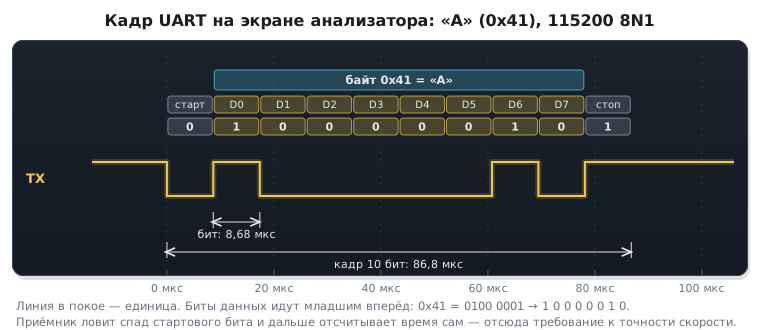
The idle line holds a one. Transmission begins with a start bit — a transition to zero — followed by the data bits least significant first, an optional parity bit and one or two stop bits (a one again).
The standard notation "115200 8N1" means: 115200 baud, 8 data bits, no parity (N), one stop bit.
There is no synchronisation at all — the receiver catches the edge of the start bit and from then on counts the time itself. Hence the main requirement: both sides must have close clock frequencies. A mismatch of more than 2–3 % breaks reception.
This is what the frame of the character "A" looks like on a logic analyser screen:
16.2 Calculating the baud rate
The rate is set by a divider in the BRR register:
USART1->BRR = (частота_шины + baud / 2u) / baud;
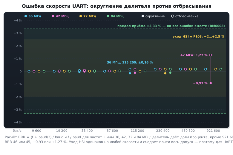
Adding half the baud rate before dividing rounds to the nearest instead of dropping the fractional part. A small thing that halves the largest possible divider error — from a whole unit to a half.
⚠️ The divider is calculated from the frequency of its own bus, and they differ. On the F1
USART1sits on APB2 (72 MHz), whileUSART2andUSART3are on APB1 (36 MHz). One and the same setup code applied to different ports gives different baud rates. On the F4 it is the same story:USART1andUSART6on APB2, the rest on APB1.
How critical this is shows in the numbers:
| Port | Frequency | Divider for 115200 | Actual rate | Error |
|---|---|---|---|---|
USART1 |
72 MHz | exactly 625 | 115200 | 0 % |
USART2 |
36 MHz | 312.5 → 313 | 115015 | 0.16 % |
USART2 without rounding |
36 MHz | 312 | 115384 | 0.16 % |
USART2 on the F4 |
42 MHz | 364.58 → 365 | 115068 | 0.11 % |
USART2 on the F4 without rounding |
42 MHz | 364 | 115384 | 0.16 % |
At 36 MHz the divider of 312.5 lies exactly in the middle, and both errors are equal in magnitude; at 42 MHz rounding already wins. All the errors are acceptable. Problems start when the clock comes from the internal HSI oscillator. On the F103 the factory trimming keeps it within −1.1…+1.8 % at 25 °C, and over the whole temperature range −2…+2.5 %. This error is relative and the same at any baud rate, and together with the error of the other side it approaches the reception limit. So a UART outside room conditions needs a crystal (section 6). A high baud rate adds its own: the divider is small, and its rounding error grows.
16.3 🔧 Transmission
void usart1_send_byte(uint8_t b)
{
    while (!(USART1->SR & USART_SR_TXE)) { }   /* можно класть следующий байт */
    USART1->DR = b;
}

void usart1_send_string(const char *s)
{
    while (*s) {
        usart1_send_byte((uint8_t)*s++);
    }
    while (!(USART1->SR & USART_SR_TC)) { }    /* всё ушло в линию */
}
⚠️
TXEandTCare not the same thing.TXEmeans that the byte has been moved from the data register to the shift register and the next one can be put there.TCmeans that the last bit has physically left the pin. The difference shows up in two places: when switching the direction of a half-duplex line (RS‑485) and when going to sleep right after transmitting. Wait only forTXEand you cut off the end of the message.
16.4 Reception: three ways and one trap
By polling — simple, but the processor is busy waiting and it is easy to miss a byte. Suitable for debug output, not suitable for reception.
By interrupt — each received byte calls a handler. A working option for moderate speeds.
Through DMA — bytes are stored in a buffer by themselves. The only sensible way for a data stream.
void USART1_IRQHandler(void)
{
    uint32_t sr = USART1->SR;

    /* Переполнение: пришёл байт, пока предыдущий не забрали. */
    if (sr & USART_SR_ORE) {
        (void)USART1->DR;
        return;
    }

    if (sr & USART_SR_RXNE) {
        uint8_t b = (uint8_t)USART1->DR;     /* чтение сбрасывает RXNE */
        /* ... */
    }
}
⚠️ An overrun must be cleared. If a byte arrived before you took the previous one, the
OREflag is set, and the new byte is lost. The receiver itself on the F1 and F4 does not stop: the next byte goes intoDRas soon as the previous one has been read. The flag is cleared by the sequence "readSR, thenDR" — which is what the handler above does. A flag left standing is dangerous: withRXNEIE, or with DMA reception withEIE, it raises the interrupt again and again, and the device looks hung. This happens whenDRis read by DMA — it does not readSR— or when a byte arrived between the reads ofSRandDR:OREis set butRXNEis not, and a handler that looks only atRXNEwill not clear the flag. In HAL, reception stops for good: onOREit is aborted, and it has to be restarted inHAL_UART_ErrorCallback. On the new-style USART the flag is cleared by writing toICR(16.9).
16.5 🔧 Receiving variable-length packets
A classic task: messages of different lengths arrive, and the delimiter is not known in advance. You cannot wait for a fixed number of bytes, and parsing every byte in an interrupt is expensive.
The solution is idle line detection. If after the last byte the line
was silent for longer than one frame time, the IDLE flag is set: the packet
has ended.
USART1->CR1 |= USART_CR1_RXNEIE | USART_CR1_IDLEIE;

/* в обработчике */
if (sr & USART_SR_IDLE) {
    (void)USART1->DR;          /* снять флаг: чтение SR, затем DR */
    /* здесь пакет длиной rx_len готов к разбору */
    rx_len = 0;
}
The proper industrial scheme combines this with DMA: the controller stores
bytes in a circular buffer without the processor, and the IDLE interrupt
fires once per packet. How many bytes exactly arrived is found
from the DMA remaining transfer counter (section 9).
The result is reception of any length at any speed at the cost of one interrupt per message.
16.6 printf to the port
The most popular debugging method when a debugger is unavailable or gets in the way (for example, a motor must not be stopped).
It is enough to redirect the standard library output to the port — in Keil this is
overriding fputc, in GCC _write. After that ordinary
printf works.
⚠️
printfis expensive. It pulls in several kilobytes of code, and formatted output of floating-point numbers even more, and slowly. On a chip with 64 KB of Flash this is noticeable. Lightweight alternatives: your own number output function, compact formatting libraries or sending raw data and parsing it on the computer side. Exact figures for the F103 are in section 74.4: printing an integer adds about half a kilobyte, a floating-point value more than four.
The second drawback is blocking: while a string goes out on a 115200 baud line, milliseconds pass. In an interrupt handler this is unacceptable (section 7); there either put the data in a buffer or output through DMA.
16.7 ⚠️ Signal levels: do not mix them up
A subtlety that burns out pins.
| What | Levels |
|---|---|
| microcontroller UART | 0 / 3.3 V |
| a computer's RS‑232 port | ±12 V, inverted |
| RS‑485 | a differential pair |
Connecting an STM32 pin directly to a classic COM port will destroy the pin.
A level converter is needed. That is why a USB–UART adapter is used
for debugging. But check its levels before connecting:
many cheap adapters work at 5 V by default and are switched
with a 3.3/5 V jumper. A five-volt TX may only be applied to a pin
with 5 V tolerance — marked FT in the pin table of the datasheet. On the F103 PA10
(USART1 receive) is such a pin, and PA3 (USART2 receive, as in 16.8) is not
(appendix E).
Separately on compatibility: the adapter must have a common
ground with the board, and the TX of one goes to the RX of the other — the lines cross over.
A lack of communication is most often explained by exactly this, not by the settings.
16.8 🔧 A Modbus RTU slave
Modbus RTU over UART is the most widespread protocol of industrial instruments: meters, frequency inverters, sensors on an RS-485 bus. The frame and CRC are covered in detail in section 89.4. Here is a complete slave: how to tell from the UART where a frame ended, what to check and how to reply.
A character is 11 bits: start, 8 data bits, a parity bit and stop. Without
parity a second stop bit is put in its place. On the STM32 the parity bit
is included in the word length: 8 data bits with parity is a nine-bit word,
M = 1 and PCE = 1. In DR the parity comes as the ninth bit, and casting
to uint8_t drops it.
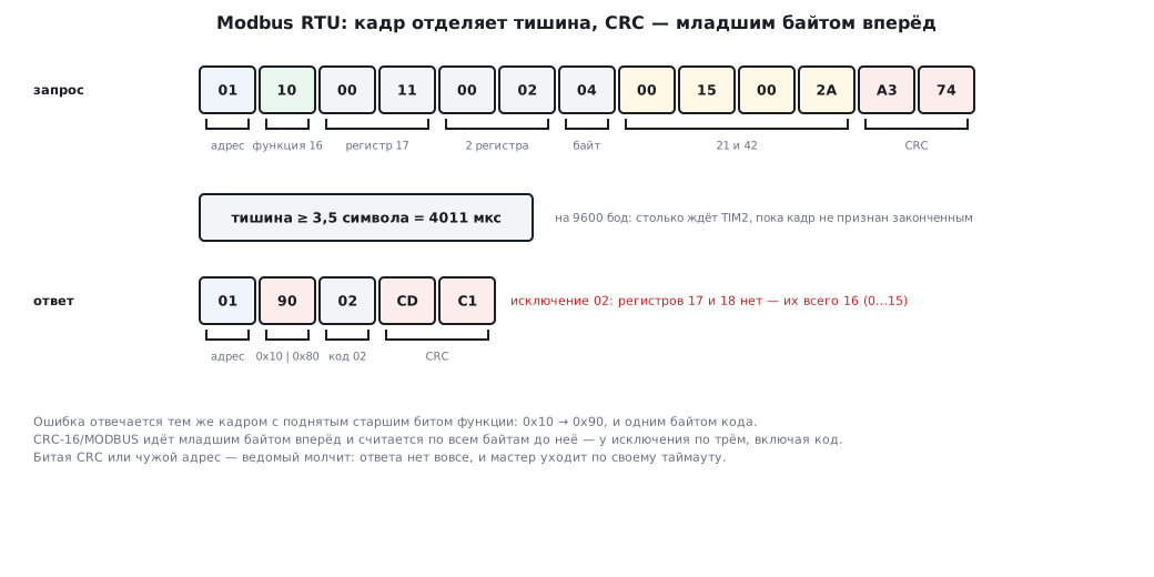
The end of a frame is a silence of 3.5 characters: at 9600 baud that is 4011 µs.
The IDLE flag (16.5) is set after a silence of one character — that is too little.
The silence is timed by a timer in one-pulse mode. Each received byte
resets it and starts it again; if the timer runs out, the frame is over.
A gap inside a frame longer than 1.5 characters (1719 µs) is considered an error
by the standard. The simple scheme does not catch it, but such a frame is weeded out by the CRC anyway.
Above 19 200 baud the pauses are not counted in characters: the standard recommends fixed ones — 1750 µs for the end of a frame and 750 µs for a gap inside it (section 89.4). Otherwise at 115 200 baud 3.5 characters are only 335 µs, and the slave would take any hesitation of the master for the end of a frame — for example, of a computer with a USB — RS-485 converter.
void USART2_IRQHandler(void)
{
    uint32_t sr = USART2->SR;
    uint8_t b = (uint8_t)USART2->DR;    /* чтение SR, затем DR сбрасывает флаги; бит 8 — чётность */
    if (sr & (USART_SR_PE | USART_SR_FE))
        rx.overflow = 1;                /* битый символ — весь кадр в корзину */
    else if (sr & USART_SR_RXNE)
        mb_rx_byte(&rx, b);
    TIM2->CNT = 0;                      /* каждый байт откладывает конец кадра */
    TIM2->CR1 |= TIM_CR1_CEN;
}

void TIM2_IRQHandler(void)
{
    TIM2->SR = 0;
    frame_len = mb_rx_end(&rx);         /* тишина 3,5 символа — кадр закончен */
}

/* Ответ: включить передатчик, выдать байты, дождаться TC — не TXE — и
 * только тогда выключить: иначе обрежется последний байт (раздел 89.4) */
static void mb_send(const uint8_t *p, size_t n)
{
    GPIOA->BSRR = 1u << 1;
    for (size_t i = 0; i < n; i++) {
        while (!(USART2->SR & USART_SR_TXE)) { }
        USART2->DR = p[i];
    }
    while (!(USART2->SR & USART_SR_TC)) { }
    GPIOA->BSRR = 1u << (1 + 16);
}
The setup — USART2 on PA2 and PA3, the DE pin of the RS-485 transceiver on PA1:
| F103 | F407 | |
|---|---|---|
| USART2 | APB1 36 MHz, BRR = 3750 |
APB1 42 MHz, BRR = 4375 |
| TIM2 | doubled 72 MHz, PSC = 71 — 1 µs tick |
doubled 84 MHz, PSC = 83 — 1 µs tick |
| pause | ARR = 4010, OPM = 1 |
the same |
| pause above 19 200 baud | ARR = 1749 — 1750 µs |
the same |
| word | M = 1, PCE = 1 |
the same |
On both chips the rate comes out at exactly 9600 baud, with no error.
Frame processing is a portable function, the same for any chip:
/* Обработать кадр: вернёт длину ответа в resp или 0 — не отвечать
 * (обрезанный кадр, неверная CRC, чужой адрес, широковещательный адрес 0). */
size_t mb_process(uint8_t addr, const uint8_t *req, size_t n, uint8_t *resp)
{
    if (n < 4 || n > MB_ADU || mb_crc(req, n - 2) != (uint16_t)(req[n - 2] | (req[n - 1] << 8)))
        return 0;
    int broadcast = req[0] == 0;
    if (!broadcast && req[0] != addr)
        return 0;
    uint8_t fn = req[1];
    size_t k;
    if (fn == 3 && !broadcast) {
        uint16_t first = n == 8 ? be16(req + 2) : 0, count = n == 8 ? be16(req + 4) : 0;
        if (count < 1 || count > 125) {
            k = mb_error(resp, addr, fn, MB_ILLEGAL_VALUE);
        } else if ((uint32_t)first + count > MB_REGS) {
            k = mb_error(resp, addr, fn, MB_ILLEGAL_ADDRESS);
        } else {
            resp[0] = addr;
            resp[1] = fn;
            resp[2] = (uint8_t)(2 * count);
            for (uint16_t i = 0; i < count; i++) {
                resp[3 + 2 * i] = (uint8_t)(mb_regs[first + i] >> 8);
                resp[4 + 2 * i] = (uint8_t)mb_regs[first + i];
            }
            k = mb_finish(resp, 3u + 2u * count);
        }
    } else if (fn == 16) {
        uint16_t first = n >= 11 ? be16(req + 2) : 0, count = n >= 11 ? be16(req + 4) : 0;
        if (count < 1 || count > 123 || req[6] != 2 * count || n != 9u + req[6]) {
            k = mb_error(resp, addr, fn, MB_ILLEGAL_VALUE);
        } else if ((uint32_t)first + count > MB_REGS) {
            k = mb_error(resp, addr, fn, MB_ILLEGAL_ADDRESS);
        } else {
            for (uint16_t i = 0; i < count; i++)
                mb_regs[first + i] = be16(req + 7 + 2 * i);
            for (int i = 0; i < 6; i++)             /* ответ: адрес, функция, первый регистр, число */
                resp[i] = req[i];
            k = mb_finish(resp, 6);
        }
    } else {
        k = mb_error(resp, addr, fn, MB_ILLEGAL_FUNCTION);
    }
    return broadcast ? 0 : k;
}
be16 assembles a number from two bytes, most significant first. mb_finish appends
the CRC least significant byte first. mb_error builds an exception response: the function
number with the top bit set and the reason code. The function takes 40
bytes of stack, the reply is assembled directly in the transmit buffer.
| What arrived | What the slave does |
|---|---|
| someone else's address | stays silent |
| wrong CRC or a truncated frame | stays silent — the master will repeat the request |
| address 0, broadcast | performs the write and does not reply |
| function not supported | exception 01 |
| register out of range | exception 02 |
| wrong register count or length | exception 03 |
A frame is no longer than 256 bytes, so up to 125 registers can be read and up to 123 written at a time. The longest frame at 9600 baud takes 293 ms, and 8 of the 11 bits of a character are payload — 72.7 % of the line rate.
The experiment. Against the same mb_process built for a computer
a real pymodbus master was run. RTU frames went over TCP the way
an Ethernet — RS-485 converter passes them, and the end of a frame was detected
by the same pause:
| What the master sent | The slave's reply |
|---|---|
| read registers 0–3, function 03 | 100, 101, 102, 103 |
| write 21 and 42 to registers 2 and 3, function 16 | acknowledgement; a read gives 100, 101, 21, 42 |
| read registers 14–17, though there are only 16 | exception 02 |
| function 01 | exception 01 |
| a request to address 2 | silence |
| a frame with a corrupted CRC | silence |
| broadcast write of 777 to register 5 | silence; a read gives 777 |
01 10 00 11 00 02 04 00 15 00 2A A3 74 — a write to registers 17 and 18 |
exception 02: 01 90 02 CD C1 |
All ten frames were separated by the pause, none stuck to its neighbour.
⚠️ Typical mistakes of home-made slaves. - The CRC is read as
*(uint16_t *)(buf + n). This is an unaligned read (on Cortex-M0 aHardFault), and it depends on the byte order. The CRC is assembled from two bytes: the low one first. - The register number from the request is not checked, and a request like the last one in the table writes past the end of the array. - The write data is taken from byte 6. But that is the byte count, and the data starts at byte 7, most significant first. - The reply to a write is assembled from 5 bytes. It needs 6 — address, function, first register, register count — plus the CRC. - The exception CRC is computed over two bytes. It must be over three, including the code.
16.9 F0 and G0: the new-style USART
On the F0 and G0 (as on the F3, F7, L4 and later) the USART block is different: instead of two registers
SR and DR there are four. Code from the F103 does not build on the F0: "no member named 'SR'
in 'USART_TypeDef'".
| F1, F4 | F0 | G0 | |
|---|---|---|---|
| flags | SR |
ISR (0x1C) |
ISR |
| clearing flags | by reading SR and DR |
writing to ICR (0x20) |
writing to ICR |
| receive / transmit | one DR |
RDR (0x24) / TDR (0x28) |
RDR / TDR |
| FIFO, prescaler | no | no | yes: FIFOEN, PRESC |
| USART2 clock | APB1ENR |
APB1ENR |
APBENR1 |
The divider is calculated by the same formula as in 16.2: at 48 MHz on the F0 it is 417, at 64 MHz on the G0 it is 556, both give 115 107 baud, an error of 0.08 %.
Transmit and receive on the F0:
while (!(USART2->ISR & USART_ISR_TXE)) {                /* флаги — в ISR, а не в SR */
}
USART2->TDR = (uint8_t)c;                               /* передача — свой регистр TDR */
if (USART2->ISR & USART_ISR_ORE)
    USART2->ICR = USART_ICR_ORECF;                      /* переполнение сбрасывается в ICR */
return (int)(USART2->RDR & 0xFFu);                      /* чтение RDR сбрасывает RXNE */
The overrun is cleared by you. On the F1 the ORE flag went away when SR and
DR were read; here it does not go away by itself, and while it is set, the receiver does not accept new
bytes. Hence the classic: "after the first overrun the UART went silent for ever".
It is cleared by writing USART_ICR_ORECF to ICR.
G0: the FIFO. With the FIFOEN bit the transmitter and receiver get
a FIFO, and the flags change meaning — this is visible from the names: TXE_TXFNF is "the FIFO
has room", RXNE_RXFNE is "the FIFO is not empty":
USART2->CR1 = USART_CR1_FIFOEN | USART_CR1_TE | USART_CR1_RE | USART_CR1_UE;
while (!(USART2->ISR & USART_ISR_TXE_TXFNF)) {          /* с FIFO: «в очереди есть место» */
}
if (!(USART2->ISR & USART_ISR_RXNE_RXFNE))              /* с FIFO: «очередь не пуста» */
The PRESC prescaler divides the block clock before BRR — it is needed at slow
baud rates, when the divider does not fit in 16 bits. Zero in it means no division.
16.10 Pitfalls
Garbage instead of text. The baud rates do not match or the divider was calculated wrongly for this bus. Check whether your port sits on APB1 or APB2.
Reception goes silent after a data stream. The ORE overrun flag was not cleared
or the HAL reception it aborted was not restarted (16.4).
The end of a message is cut off. TXE was waited for instead of TC before sleep
or switching direction.
The first byte is lost. The receiver was enabled after the other side had started transmitting, or there is garbage from a transient at power-on.
Nothing works, the lines are swapped. TX must go to RX.
It works only with the debugger. A sign of a race: when stepping, bytes have time to be processed, at full speed they do not. Look for an overrun.
Cyrillic in the terminal. The UART transmits bytes, the terminal chooses the encoding. If the microcontroller sends UTF‑8 and the terminal expects CP866, you get mush.
The Modbus slave replies every other time. The end of a frame is detected by IDLE or by
a fixed delay, and frames are sometimes merged, sometimes cut.
A parity error on every byte. Parity was enabled, but the word was left
8-bit (M = 0): the parity bit ate the top data bit.
The master sees a timeout although the reply went out. The RS-485 transmitter was switched off
on TXE, and the last CRC byte was cut off.
16.11 Summary
- A frame: start, data least significant bit first, optional parity, stop. There is no synchronisation — the clocks of the two sides must agree to within a couple of percent.
- The divider is calculated from the frequency of its own bus:
USART1on APB2, the rest on APB1, and with the same code the baud rates come out different. - Rounding to the nearest when calculating the divider halves the largest possible divider error — from one to a half.
TXE— the next byte can be put in,TC— everything has physically gone out. They must not be confused.- The
OREoverrun on the F1 and F4 is cleared by readingSR, thenDR; a flag left standing makes the interrupt loop, and HAL reception is aborted by it. - Variable-length packets are received by the pause on the line; the best scheme is
DMA plus the
IDLEinterrupt. printfis convenient but expensive in memory and blocks execution.- Microcontroller levels are 3.3 V; a classic COM port with its ±12 V must not be connected directly.
- Modbus RTU over UART: an 11-bit character (parity on the STM32 means
M= 1), the end of a frame is 3.5 characters of silence timed by a timer. To someone else's address and a bad CRC the slave stays silent, to errors it replies with exceptions 01, 02, 03.
Full sources
uart_f0.c — USART2 of the STM32F072 at 48 MHz.
/* Раздел 16.9: USART2 на PA2/PA3 у STM32F072 при 48 МГц.
 * Блок USART нового образца: флаги в ISR, сброс флагов — в ICR, TDR и RDR отдельно. */
#include <stddef.h>
#include "stm32f0xx.h"

#define PCLK_HZ 48000000u
#define BAUD 115200u
#define BRR_VALUE ((PCLK_HZ + BAUD / 2u) / BAUD)

_Static_assert(BRR_VALUE == 417u, "делитель — та же формула, что у F1 и F4");
_Static_assert(offsetof(USART_TypeDef, ISR) == 0x1Cu && offsetof(USART_TypeDef, ICR) == 0x20u, "флаги и сброс");
_Static_assert(offsetof(USART_TypeDef, RDR) == 0x24u && offsetof(USART_TypeDef, TDR) == 0x28u, "приём и передача");

void uart_init_f0(void)
{
    RCC->AHBENR |= RCC_AHBENR_GPIOAEN;
    RCC->APB1ENR |= RCC_APB1ENR_USART2EN;
    GPIOA->MODER = (GPIOA->MODER & ~(3u << 4) & ~(3u << 6)) | (2u << 4) | (2u << 6);   /* PA2, PA3 — AF */
    GPIOA->AFR[0] = (GPIOA->AFR[0] & ~(0xFu << 8) & ~(0xFu << 12)) | (1u << 8) | (1u << 12);   /* AF1 */
    USART2->BRR = BRR_VALUE;
    USART2->CR1 = USART_CR1_TE | USART_CR1_RE | USART_CR1_UE;
}

void uart_putc_f0(char c)
{
    while (!(USART2->ISR & USART_ISR_TXE)) {                /* флаги — в ISR, а не в SR */
    }
    USART2->TDR = (uint8_t)c;                               /* передача — свой регистр TDR */
}

int uart_getc_f0(void)
{
    if (USART2->ISR & USART_ISR_ORE)
        USART2->ICR = USART_ICR_ORECF;                      /* переполнение сбрасывается в ICR */
    if (!(USART2->ISR & USART_ISR_RXNE))
        return -1;
    return (int)(USART2->RDR & 0xFFu);                      /* чтение RDR сбрасывает RXNE */
}
uart_g0.c — USART2 of the STM32G071 at 64 MHz with the FIFO.
/* Раздел 16.9: USART2 на PA2/PA3 у STM32G071 при 64 МГц — с очередью FIFO. */
#include <stddef.h>
#include "stm32g0xx.h"

#define PCLK_HZ 64000000u
#define BAUD 115200u
#define BRR_VALUE ((PCLK_HZ + BAUD / 2u) / BAUD)

_Static_assert(BRR_VALUE == 556u, "64 МГц / 115200");
_Static_assert(offsetof(USART_TypeDef, PRESC) == 0x2Cu, "предделитель — отдельный регистр PRESC");

void uart_init_g0(void)
{
    RCC->IOPENR |= RCC_IOPENR_GPIOAEN;
    RCC->APBENR1 |= RCC_APBENR1_USART2EN;                   /* у G0 — APBENR1, не APB1ENR */
    GPIOA->MODER = (GPIOA->MODER & ~(3u << 4) & ~(3u << 6)) | (2u << 4) | (2u << 6);
    GPIOA->AFR[0] = (GPIOA->AFR[0] & ~(0xFu << 8) & ~(0xFu << 12)) | (1u << 8) | (1u << 12);
    USART2->PRESC = 0u;                                     /* такт без деления */
    USART2->BRR = BRR_VALUE;
    USART2->CR1 = USART_CR1_FIFOEN | USART_CR1_TE | USART_CR1_RE | USART_CR1_UE;
}

void uart_putc_g0(char c)
{
    while (!(USART2->ISR & USART_ISR_TXE_TXFNF)) {          /* с FIFO: «в очереди есть место» */
    }
    USART2->TDR = (uint8_t)c;
}

int uart_getc_g0(void)
{
    if (USART2->ISR & USART_ISR_ORE)
        USART2->ICR = USART_ICR_ORECF;
    if (!(USART2->ISR & USART_ISR_RXNE_RXFNE))              /* с FIFO: «очередь не пуста» */
        return -1;
    return (int)(USART2->RDR & 0xFFu);
}
Next: section 16а "RS-485: the line, terminators, bias and transmit
direction" — the bus, bias for the receiver threshold and DE driven by TC or by the USART itself.