 Embedded HandbookApps
16а. RS-485: the line, terminators, bias and transmit direction
In section 16.8 the Modbus RTU slave already replies over RS-485: the DE pin on PA1
is raised before the reply and dropped on the TC flag. Section 89.4 added
the rule "rate × length ≈ 10⁸", two 120 Ω terminators and a bias of
390 Ω at 3.3 V. Here — the line itself and everything around the DE pin: how
to build the bus and where to put the terminators, how to calculate the bias with one and
two terminators and with tolerances, why TXE cuts the reply off, how the USART
drives DE itself on the G4 and how long the line goes silent between request and reply.
Prerequisites: reference manuals RM0008 (F1: the TXE and TC flags) and RM0440
(G4: DE, DEAT, DEDT, receiver timeout), datasheet DS12288 (the
USART2_RTS_DE pin), the CMSIS headers of seven families from the Keil packs, the Zephyr
bindings for the STM32 USART and Modbus. The bias, bit fractions and exchange time
were computed with a PC model; the code was built with armclang for the F103 and G474, and the F103 code
was run on a computer against a model of the USART per RM0008.
Terms used in the documentation
Term Meaning differential pair (A, B) the two wires A and B half-duplex only one side transmits at a time termination resistor a resistor at the end of the line fail-safe biasing holding a defined level on the idle line stub a branch from the trunk to a device unit load the standard measure of receiver loading driver enable (DE) switching on the RS-485 transmitter receiver enable (/RE) switching on the receiver, active low transmission complete ( TC)transmission has finished driver enable assertion / deassertion time ( DEAT,DEDT)DE delay before the start bit and after the stop bit driver enable polarity ( DEP)the polarity of DE receiver timeout ( RTOEN,RTOR)silence on RX counted in bits
16а.1 The line and one exchange over it
RS-485 is a pair of wires A and B. The receiver looks only at the difference
A − B: interference that is the same on both wires is subtracted. There is one transmitter
at a time — the line is half-duplex: while the master talks,
everyone else listens, then the other way round. Each device switches the direction
itself with the transceiver pins: DE enables the transmitter
(active high), /RE the receiver (active low), as the Zephyr binding
zephyr,modbus-serial describes them. If DE and /RE are on one pin,
a one on it simultaneously enables the transmitter and disables the receiver.
The third wire is the common. The receiver sees the difference A − B only as long as both wires do not move too far from its ground, and the permissible common-mode voltage is in the transceiver datasheet. Devices in different cabinets have different grounds (section 54.1), and without a common wire or isolation the line works until the first potential difference.
One Modbus exchange at 9600 baud looks like this:
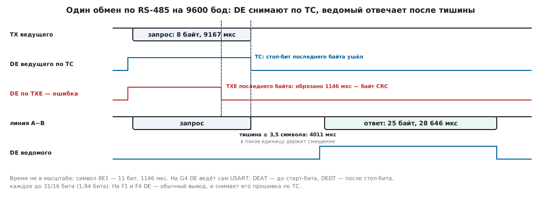
The figure shows everything this section is about: who holds the line during the pause (16а.3), when to drop DE (16а.4 and 16а.5) and how long the exchange lasts (16а.6).
16а.2 Topology: bus, stubs, terminators
Devices hang on one trunk in a daisy chain: the cable goes into a device and comes out to the next one. Such a line has two ends, and the terminators go exactly there — one at each physical end (section 89.4). A star of several branches has as many ends as branches, and it cannot be matched with two resistors.
A stub — the piece of wire from the trunk to the transceiver — is itself an unmatched line. By the rule of section 160.1 it is invisible as long as its delay is less than roughly a sixth of the transmitter's edge time. The edge is in the transceiver datasheet: chips with slew-rate limiting have longer edges, and they tolerate longer stubs. Keep the stub short, and put the terminals right at the transceiver.
A terminator in every device is a common assembly mistake: ten 120 Ω resistors in parallel give 12 Ω. A 390 Ω bias at 3.3 V on such a load gives 50 mV — four times below the threshold, and the line picks up noise during pauses again. So the terminator jumper in a device is switched on only at the two end devices.
The load from receiver inputs is counted by the standard in unit loads. How many units (or what fraction of a unit) a transceiver takes and how many devices can hang on the line is written in its datasheet. There are no numbers here: the text of the standard is not on disk, and they differ between chips — take them from the datasheet of yours.
16а.3 Bias: calculating for the threshold with one and two terminators
The bias is a resistor Rb from the supply to A and an identical one from B to ground. At rest current flows through them and the terminators, and between A and B you get
VAB = Vcc × Rt / (2 × Rb + Rt),
where Rt is the terminators in parallel: 120 Ω if there is one, and 60 Ω if there are two. A above B — the receiver outputs a one, that is, the very idle state of the UART. We take the receiver threshold as 200 mV — the limit from section 89.4: from it upwards the receiver must output a one; yours is in its datasheet. The model does not account for the receiver inputs: with them VAB is a little lower still.
The nominal is not enough: resistors and the supply vary. A PC model looks for Rb so that 200 mV is reached even in the worst case — the supply 5 % low, Rb 1 % high, Rt 1 % low — and takes the nearest lower value of the E12 series:
| Supply | Terminators | Rb at most | With tolerances | E12 series | VAB | Worst case | Current |
|---|---|---|---|---|---|---|---|
| 5 V | 1 | 1440 Ω | 1338 Ω | 1200 Ω | 238 mV | 222 mV | 1.98 mA |
| 5 V | 2 | 720 Ω | 669 Ω | 560 Ω | 254 mV | 237 mV | 4.24 mA |
| 3.3 V | 1 | 930 Ω | 863 Ω | 820 Ω | 225 mV | 210 mV | 1.88 mA |
| 3.3 V | 2 | 465 Ω | 432 Ω | 390 Ω | 236 mV | 220 mV | 3.93 mA |
What follows from the table:
- Calculate for two terminators. A bias calculated for one (820 Ω at 3.3 V) gives 116 mV on a line with two — below the threshold. The second terminator appears when the line is extended to the last device, and communication that worked on the desk breaks in the cabinet.
- 680 Ω at 5 V is on the edge. Nominally 211 mV, but in the worst case 197 mV. Section 89.4 names 560–680 Ω; with tolerances 560 remains.
- One set per line. If the bias is switched on in every device, the sets add up in parallel:
| 390 Ω sets at 3.3 V | VAB | Current | Transmitter load |
|---|---|---|---|
| 1 | 236 mV | 3.93 mA | 55.7 Ω |
| 2 | 440 mV | 7.33 mA | 52.0 Ω |
| 4 | 776 mV | 12.94 mA | 45.9 Ω |
The threshold margin grows, but so do the current and the transmitter load: for the signal the supply is the same as ground, and each set hangs on the line as 2 × Rb. The budget of the isolated port from section 54.4 allows 10 mA for the line pull resistors: one set fits there, four no longer do. What load the transmitter can drive is stated in its datasheet.
Many newer transceivers have the threshold shifted so that silence reads as a one even without bias (section 89.4). This is visible in the datasheet from the receiver threshold; then the bias resistors are not needed.
16а.4 DE by hand on the F103: by TC, not by TXE
The USART of the F1 and F407 has no hardware DE (16а.5), and the DE pin is an ordinary
output. In section 16.8 it is dropped by polling TC in a loop. For a master
that has no time to wait — the same with interrupts. RM0008 (27.3.2) on
the flags: TXE is set when a byte has been moved from the data register to the
shift register, that is, at the moment it has only started going out on the line;
TC when the frame has gone out completely and there is no new data. Hence the PC model:
for an 8-byte request at 9600 baud the TXE of the last byte comes at
8021 µs, TC at 9167 µs; DE dropped on TXE cuts off 1146 µs —
the last byte, the high byte of the CRC. With a one-byte message it is worse: while
the transmitter is free, a write to DR goes straight into the shift register, and
TXE stays set — DE falls before the byte has started.
The second trap is reset: USART_SR after reset equals 0x00C0, that is,
TC is already set. It is cleared by the pair "read SR — write DR".
Enable TCIE before the first byte — and the very first interrupt comes from
the old TC. So TCIE is enabled only after the last byte
has been written:
void rs485_send(const uint8_t *p, uint32_t n)
{
    if (n == 0)
        return;
    while (tx_busy) {
    }
    tx_p = p;
    tx_n = n;
    tx_busy = 1;
    USART2->CR1 &= ~USART_CR1_RE;               /* своё эхо не принимать */
    GPIOA->BSRR = 1u << 1;                      /* DE = 1: передатчик на линии */
    USART2->CR1 |= USART_CR1_TXEIE;             /* байты кладёт прерывание; TCIE пока нельзя: TC = 1 с самого сброса */
}

void USART2_IRQHandler(void)
{
    uint32_t sr = USART2->SR;
    uint32_t cr1 = USART2->CR1;
    if ((cr1 & USART_CR1_TXEIE) && (sr & USART_SR_TXE)) {
        USART2->DR = *tx_p++;                   /* чтение SR, затем запись DR сбрасывают TC */
        if (--tx_n == 0)                        /* последний байт только начал уходить: ждать TC, а не TXE */
            USART2->CR1 = (uint16_t)((cr1 & ~USART_CR1_TXEIE) | USART_CR1_TCIE);
    } else if ((cr1 & USART_CR1_TCIE) && (sr & USART_SR_TC)) {
        GPIOA->BSRR = 1u << (1 + 16);           /* стоп-бит последнего байта в линии: DE = 0 */
        USART2->CR1 = (uint16_t)((cr1 & ~USART_CR1_TCIE) | USART_CR1_RE);
        tx_busy = 0;
    }
    if (sr & USART_SR_RXNE)
        rs485_rx_byte((uint8_t)USART2->DR);
}
The USART receiver (RE) is off during transmission: then your own echo does not
get into reception, however /RE is connected — together with DE or to
ground. RX is pulled up to the supply: if the receiver output releases the line
when disabled (on many chips it does, see the datasheet), without the
pull-up the pin would float.
The same file was built on a computer together with a model of the USART per RM0008 —
time in bits, TXE and TC behave as in the description above:
| Variant | Bytes | Bits on the line | Bits with DE = 0 |
|---|---|---|---|
by TC — the code above |
8 | 88 | 0 |
by TC — the code above |
1 | 11 | 0 |
by the TXE of the last byte |
8 | 88 | 11 |
by the TXE of the last byte |
1 | 11 | 11 |
TCIE at once, the handler checks TC first |
8 | 88 | 88 |
With TC, DE falls exactly at the boundary of the last stop bit. Between raising
DE and the start bit there is only the interrupt entry. If the transceiver needs
time to switch on (it is in the datasheet), wait it out before the first write to
DR — on the G4 the DEAT field does this.
16а.5 Hardware DE: the G474 and which families can do it
In the new USART the DE pin is driven by the block itself. RM0440 (37.5.20): the DEM bit
in USART_CR3 outputs the DE signal on the RTS pin; DEP selects the polarity
(0 — active high); DEAT in USART_CR1 is the time from raising DE to
the start of the start bit, DEDT from the end of the last stop bit to dropping DE.
Both fields are 5 bits and count in fractions of a bit: 1/16 with OVER8 = 0 and 1/8
with OVER8 = 1. They can only be written with UE = 0. The Zephyr binding
st,stm32-uart calls them de-assert-time and de-deassert-time —
"in sixteenths of a bit, from 0 to 31", in HAL the same is done by
HAL_RS485Ex_Init.
Which families can do this — from the CMSIS headers in the Keil packs:
| Family | Header | DEM, DEP |
DEAT, DEDT |
RTOEN |
|---|---|---|---|---|
| F0 | stm32f072xb.h | yes | yes | yes |
| F1 | stm32f10x.h | no | no | no |
| F3 | stm32f303xc.h | yes | yes | yes |
| F4 | stm32f407xx.h | no | no | no |
| F7 | stm32f767xx.h | yes | yes | yes |
| G4 | stm32g474xx.h | yes | yes | yes |
| L4 | stm32l476xx.h | yes | yes | yes |
How much that is in time:
| Rate | Fraction with OVER8 = 0 |
Maximum, 31 fractions | The same with OVER8 = 1 |
|---|---|---|---|
| 9600 baud | 6.5104 µs | 201.82 µs | 403.65 µs |
| 115 200 baud | 0.5425 µs | 16.82 µs | 33.64 µs |
| 1 Mbit/s | 0.0625 µs | 1.94 µs | 3.88 µs |
31 fractions are 1.9375 bits with OVER8 = 0 and 3.875 bits with OVER8 = 1.
DEAT is chosen like this: the transmitter enable time from the datasheet × rate × 16,
rounded up. Suppose the transceiver needs 3 µs: at 115 200 baud
this is DEAT = 6, and at 1 Mbit/s 48 fractions are needed — the field cannot hold that many,
and OVER8 = 1 remains (24 fractions of 1/8).
Code for the G474 — USART2 on the same PA1, PA2 and PA3 as on the F103 in section 16.8; according to datasheet DS12288 PA1 is USART2_RTS_DE on AF7, with TX and RX next to it on the same AF7:
#define DE_TIME   16u       /* DEAT и DEDT: 16 долей по 1/16 бита = 1 бит (OVER8 = 0) */
#define RTO_BITS  39u       /* 3,5 символа по 11 бит = 38,5 бита -> 39 */

#define CR1_RS485 ((DE_TIME << USART_CR1_DEAT_Pos) | (DE_TIME << USART_CR1_DEDT_Pos) | \
                   USART_CR1_M0 | USART_CR1_PCE | USART_CR1_RTOIE | USART_CR1_TE | USART_CR1_RE)
void rs485_g4_init(void)
{
    RCC->AHB2ENR |= RCC_AHB2ENR_GPIOAEN;
    RCC->APB1ENR1 |= RCC_APB1ENR1_USART2EN;
    GPIOA->AFR[0] = (GPIOA->AFR[0] & ~0xFFF0u) | 0x7770u;   /* PA1, PA2, PA3 — AF7 */
    GPIOA->MODER = (GPIOA->MODER & ~0xFCu) | 0xA8u;         /* все три — альтернативная функция */
    USART2->BRR = 17708u;
    USART2->RTOR = RTO_BITS;
    USART2->CR2 = USART_CR2_RTOEN;
    USART2->CR3 = USART_CR3_DEM;                            /* DEP = 0: DE активен высоким уровнем */
    USART2->CR1 = CR1_RS485;                                /* DEAT, DEDT и формат пишут при UE = 0 */
    USART2->CR1 = CR1_RS485 | USART_CR1_UE;
}
BRR = 170 MHz / 9600 = 17708: a rate of 9600.18 baud, an error of +0.0019 %.
DEAT = DEDT = 16 — one bit, 104.2 µs at 9600 baud. Static
assertions in the file pin the bit numbers per RM0440: DEM and DEP are bits
14 and 15 of CR3, DEAT 25:21, DEDT 20:16 of CR1. armclang reduces
the USART2 setup (address 0x4000 4400) to six writes: BRR = 0x452C,
RTOR = 0x27, CR2 = 0x800000, CR3 = 0x4000, CR1 = 0x0610140C
and then 0x0610140D — the same CR1 with UE. Transmission after that is
simply a write to TDR: DE rises DEAT before the start bit and falls
DEDT after the stop bit without the firmware taking part.
The price: DE comes out on the RTS pin, so hardware RTS flow control can no longer be used on this USART.
16а.6 Frame time, line turnaround and 3.5 characters
A Modbus RTU character is 11 bits (section 16.8). The request "read 10 registers" is 8 bytes, the reply to it 25: address, function, byte count, 20 bytes of data and CRC. Between frames the line is silent for at least 3.5 characters, above 19 200 baud a constant 1750 µs (section 198в.3). How long one exchange takes, without the processing time in the slave:
| Rate | Character | Request | Pause | Reply | Exchange | Exchanges per second, at most |
|---|---|---|---|---|---|---|
| 9600 baud | 1145.8 µs | 9167 µs | 4011 µs | 28 646 µs | 45 834 µs | 21.8 |
| 19 200 baud | 572.9 µs | 4583 µs | 2006 µs | 14 323 µs | 22 918 µs | 43.6 |
| 115 200 baud | 95.5 µs | 764 µs | 1750 µs | 2387 µs | 6651 µs | 150.4 |
At 115 200 baud the two 1750 µs pauses are more than half the exchange: raising the rate further is almost useless, and it shortens the line length by the rule of 89.4.
Line turnaround is the moment when the master releases the line and the slave
takes it. The slave starts replying no earlier than the end of the
3.5-character silence: that is how it recognises the end of the request. So the master has
4011 µs at 9600 baud to drop DE. DEDT = 16 takes 104.2 µs, interrupt
entry on the F103 a few microseconds: the margin is huge. The danger is not
Modbus but home-grown protocols where the slave replies at once: then the master's delay
in dropping DE must be shorter than the shortest reply delay.
End of frame on the G4 without a timer. In sections 16.8 and 198в the silence is counted by
a timer. The new USART has a receiver timeout for this: RTOEN in CR2 and
the number of bits of silence in RTOR; RTOF is set if the pause is longer than the value
plus 2 fractions of a bit (RM0440). 3.5 characters are 38.5 bits:
RTO |
RTOF after |
Needed at least | Result |
|---|---|---|---|
| 38 | 38.125 bits | 38.5 bits | too early: the frame is cut |
| 39 | 39.125 bits | 38.5 bits | suitable |
Hence RTO_BITS = 39 in the code above. A gap inside a frame of up to 1.5 characters
(16.5 bits) is allowed by the protocol — it will not run the counter out. RM0440 in the section
on Modbus takes 2 characters, 22 bits, as an example; the protocol needs 3.5.
The constant 1750 µs for rates above 19 200 baud is, at 115 200 baud,
202 bits.
Isolation and protection. If devices are powered from different grounds — a digital isolator and an isolated converter (sections 54.4 and 54.6). Everything that goes out to the terminals gets a suppressor at the connector (sections 62.9 and 203.4), and against common-mode interference on the cable a common-mode choke (section 168).
16а.7 Pitfalls
Communication works on the desk and fails in the cabinet. The bias was calculated for one terminator, but on site there are two: 820 Ω at 3.3 V gives 116 mV instead of the required 200. Calculate for two — 390 Ω.
Noise in pauses, false start bits. A terminator is switched on in every device: ten of 120 Ω are 12 Ω, and the bias gives 50 mV. Terminators only at the two ends.
It works, but fails at the slightest thing. 680 Ω at 5 V: nominally 211 mV, but with supply and resistor tolerances 197 mV. Take 560.
The master sees a timeout although the reply went out. DE was dropped on TXE: the last
CRC byte is cut off. With a one-byte message nothing at all goes out.
DE falls before it has risen. TCIE was enabled before the first byte, and
TC has been set since reset (USART_SR = 0x00C0).
Your own echo in reception. /RE is grounded, and the receiver hears its own
transmission. Switch off RE in CR1 during transmission — or discard the echo.
On the G4 DEAT and DEDT do not change. The fields are written only with UE = 0 —
first CR1 without UE, then with it.
The receiver timeout cuts the frame. RTO = 38: RTOF comes after
38.125 bits, earlier than 3.5 characters. 39 is needed.
A star instead of a chain. A star has more than two ends — two terminators cannot match it. The trunk is a daisy chain, the stubs are short.
16а.8 Summary
- RS-485 is the pair A and B, half-duplex and a common wire; DE enables the transmitter with a high level, /RE the receiver with a low one.
- The bus is a daisy chain with two ends; a 120 Ω terminator only at them, short stubs. Ten terminators mean 12 Ω and 50 mV of bias.
- Bias: VAB = Vcc × Rt / (2Rb + Rt). With tolerances for two terminators: 390 Ω at 3.3 V (worst case 220 mV), 560 Ω at 5 V (237 mV). For one — 820 Ω and 1200 Ω, but with two terminators 820 Ω gives 116 mV.
- DE on the F1 and F4 is dropped on
TC: onTXEthe last byte is lost, 11 bits;TCIEis enabled only after the last byte. - The F0, F3, F7, G4, L4 drive DE themselves:
DEM,DEPinCR3,DEATandDEDTinCR1— up to 31 fractions of a bit (1.9375 bits withOVER8= 0). - One "10 registers" exchange at 9600 baud takes 45 834 µs, no more than 21.8 per second; at 115 200 baud 6651 µs, and the pauses there are more than half.
- The end of a Modbus frame on the G4 is the receiver timeout,
RTO= 39 bits.
Full sources
rs485_f103.c — RS-485 on the STM32F103: interrupt-driven transmission, DE dropped on the TC flag.
/* 16а: RS-485 на STM32F103 — передача по прерываниям, вывод DE снимается по флагу TC.
   USART2: PA2 — TX, PA3 — RX, PA1 — DE и /RE приёмопередатчика (как в разделе 16.8), 9600 8E1.
   Собирается armclang: -DSTM32F10X_MD -include stm32f10x.h. */
#include <stddef.h>
#include <stdint.h>

#ifdef USART_CR3_DEM
#error "у USART F1 аппаратного DE нет: такого бита в заголовке быть не должно"
#endif
_Static_assert(USART_SR_TXE == 0x80 && USART_SR_TC == 0x40, "TXE и TC — биты 7 и 6 USART_SR (RM0008)");
_Static_assert(USART_CR1_TXEIE == 0x80 && USART_CR1_TCIE == 0x40, "их прерывания — те же биты в CR1");
_Static_assert(36000000u / 9600u == 3750u && 36000000u % 9600u == 0u, "9600 бод от APB1 36 МГц без погрешности");

extern void rs485_rx_byte(uint8_t b);           /* приём кадра — раздел 16.8 */

static const uint8_t *tx_p;
static volatile uint32_t tx_n;
static volatile uint8_t tx_busy;

void rs485_init(void)
{
    RCC->APB2ENR |= RCC_APB2ENR_IOPAEN;
    RCC->APB1ENR |= RCC_APB1ENR_USART2EN;
    GPIOA->BSRR = (1u << (1 + 16)) | (1u << 3); /* DE = 0 — слушаем; подтяжка RX вверх */
    GPIOA->CRL = (GPIOA->CRL & ~0xFFF0u)
               | (0x2u << 4)                    /* PA1: выход 2 МГц — DE и /RE */
               | (0xAu << 8)                    /* PA2: альтернативная функция — TX */
               | (0x8u << 12);                  /* PA3: вход с подтяжкой — RX */
    USART2->BRR = 3750u;
    USART2->CR1 = USART_CR1_UE | USART_CR1_M | USART_CR1_PCE | USART_CR1_TE | USART_CR1_RE | USART_CR1_RXNEIE;
    NVIC_EnableIRQ(USART2_IRQn);
}

void rs485_send(const uint8_t *p, uint32_t n)
{
    if (n == 0)
        return;
    while (tx_busy) {
    }
    tx_p = p;
    tx_n = n;
    tx_busy = 1;
    USART2->CR1 &= ~USART_CR1_RE;               /* своё эхо не принимать */
    GPIOA->BSRR = 1u << 1;                      /* DE = 1: передатчик на линии */
    USART2->CR1 |= USART_CR1_TXEIE;             /* байты кладёт прерывание; TCIE пока нельзя: TC = 1 с самого сброса */
}

void USART2_IRQHandler(void)
{
    uint32_t sr = USART2->SR;
    uint32_t cr1 = USART2->CR1;
    if ((cr1 & USART_CR1_TXEIE) && (sr & USART_SR_TXE)) {
        USART2->DR = *tx_p++;                   /* чтение SR, затем запись DR сбрасывают TC */
        if (--tx_n == 0)                        /* последний байт только начал уходить: ждать TC, а не TXE */
            USART2->CR1 = (uint16_t)((cr1 & ~USART_CR1_TXEIE) | USART_CR1_TCIE);
    } else if ((cr1 & USART_CR1_TCIE) && (sr & USART_SR_TC)) {
        GPIOA->BSRR = 1u << (1 + 16);           /* стоп-бит последнего байта в линии: DE = 0 */
        USART2->CR1 = (uint16_t)((cr1 & ~USART_CR1_TCIE) | USART_CR1_RE);
        tx_busy = 0;
    }
    if (sr & USART_SR_RXNE)
        rs485_rx_byte((uint8_t)USART2->DR);
}
rs485_g474.c — RS-485 on the STM32G474: the USART drives DE itself, the receiver timeout catches the end of a frame.
/* 16а: RS-485 на STM32G474 — вывод DE ведёт сам USART2 (DEM), конец кадра Modbus ловит таймаут приёма.
   USART2: PA1 — DE (USART2_RTS_DE), PA2 — TX, PA3 — RX, все AF7; 9600 8E1 от PCLK1 170 МГц.
   Собирается armclang: -DSTM32G474xx -include stm32g4xx.h. */
#include <stdint.h>

#define DE_TIME   16u       /* DEAT и DEDT: 16 долей по 1/16 бита = 1 бит (OVER8 = 0) */
#define RTO_BITS  39u       /* 3,5 символа по 11 бит = 38,5 бита -> 39 */

#define CR1_RS485 ((DE_TIME << USART_CR1_DEAT_Pos) | (DE_TIME << USART_CR1_DEDT_Pos) | \
                   USART_CR1_M0 | USART_CR1_PCE | USART_CR1_RTOIE | USART_CR1_TE | USART_CR1_RE)

_Static_assert(USART_CR3_DEM == (1u << 14) && USART_CR3_DEP == (1u << 15), "DEM и DEP — биты 14 и 15 USART_CR3 (RM0440)");
_Static_assert(USART_CR1_DEAT_Pos == 21 && USART_CR1_DEAT_Msk == 0x03E00000u, "DEAT[4:0] — биты 25:21 CR1");
_Static_assert(USART_CR1_DEDT_Pos == 16 && USART_CR1_DEDT_Msk == 0x001F0000u, "DEDT[4:0] — биты 20:16 CR1");
_Static_assert(DE_TIME <= 31u && RTO_BITS <= USART_RTOR_RTO_Msk, "поля DEAT, DEDT — 5 бит, RTO — 24 бита");
_Static_assert(CR1_RS485 == 0x0610140Cu, "CR1: DEAT = DEDT = 16, 8E1, RTOIE, TE, RE");
_Static_assert((170000000u + 4800u) / 9600u == 17708u, "BRR для 9600 бод от 170 МГц");

void rs485_g4_init(void)
{
    RCC->AHB2ENR |= RCC_AHB2ENR_GPIOAEN;
    RCC->APB1ENR1 |= RCC_APB1ENR1_USART2EN;
    GPIOA->AFR[0] = (GPIOA->AFR[0] & ~0xFFF0u) | 0x7770u;   /* PA1, PA2, PA3 — AF7 */
    GPIOA->MODER = (GPIOA->MODER & ~0xFCu) | 0xA8u;         /* все три — альтернативная функция */
    USART2->BRR = 17708u;
    USART2->RTOR = RTO_BITS;
    USART2->CR2 = USART_CR2_RTOEN;
    USART2->CR3 = USART_CR3_DEM;                            /* DEP = 0: DE активен высоким уровнем */
    USART2->CR1 = CR1_RS485;                                /* DEAT, DEDT и формат пишут при UE = 0 */
    USART2->CR1 = CR1_RS485 | USART_CR1_UE;
}

/* Передача: DE поднимется за DEAT до старт-бита и упадёт через DEDT после стоп-бита сам */
void rs485_g4_send(const uint8_t *p, uint32_t n)
{
    while (n--) {
        while (!(USART2->ISR & USART_ISR_TXE)) {
        }
        USART2->TDR = *p++;
    }
}
Next: section 16б "Lossless UART reception: DMA into a ring, IDLE and the half buffer" — circular DMA, the position from NDTR, parsing frames without copying and the ring size from the baud rate and latency.