 Embedded HandbookApps
15в. The external MCP4725 DAC over I2C: 12 bits, fast write and EEPROM, the supply as the reference, signal generation
Section 15 covers the built-in DAC, and it opens with a warning: the STM32F103C8 on the BluePill does not have one (15.1). Instead there is PWM with a filter or an external chip. In 15б an external ADS1115 ADC was connected to the F103 over I2C; here is the reverse task — the external MCP4725 DAC on the same bus. It is the most common module: 12 bits, one output, its own supply as the reference and an EEPROM from which the code is loaded at power-up. Here: the commands and frame formats, turning a code into a voltage and what a supply reference means, the output errors and a two-point correction, how many points per second the bus lets through, a sine, a saw and a triangle from a timer and through DMA, the spectrum of the steps and the RC filter, the EEPROM write and the output shutdown modes.
Sources: RM0008 (DocID13902 Rev 17): DMA1, channel 6 is I2C1_TX, table 78,
p. 281; I2C up to 400 kHz, p. 752; master reception of more than two bytes,
p. 763; DMA requests from I2C, p. 769; the DMAEN bit in I2C_CR2, p. 775. DocID13587
Rev 17 (STM32F103x8/xB): PB6 is I2C1_SCL, PB7 is I2C1_SDA, both FT,
p. 32. The project has no document on the MCP4725. The fast write format (two
bytes: 0 0 PD1 PD0 D11…D8, then D7…D0), the five-byte read with the
RDY bit in the top bit of the first byte and the EEPROM write of 25 to 50 ms were checked against the
drivers/dac/dac_mcp4725.c driver from Zephyr 4.4.2. The rest —
the addresses, the command codes, the three-byte write and read format, the POR bit,
the power-down modes, the EEPROM endurance — comes from the manufacturer's documentation and was not
checked; it is built into the model, and everything below checks that the
driver agrees with the model, not with the chip. All numbers come from a run of the driver
_verify/dac15d/mcp15d.c on a computer (gcc 12.2.0) with our own model of the
MCP4725 as an I2C slave in Python 3.11; the firmware is built by armclang 6.24
for the Cortex-M3.
What it is called in the documentation
Original Meaning rail-to-rail output output from zero to the supply fast mode write command fast write: two bytes per code write DAC register / write DAC register and EEPROM write the DAC register / the DAC and the EEPROM power-down mode output disconnected and pulled to ground through a resistor ready/busy (RDY/BSY) EEPROM write finished / in progress power-on reset (POR) reset at power-up offset / gain error offset / gain error INL / DNL integral / differential nonlinearity settling time time for the output to settle high-speed mode (Hs) I2C at 3.4 MHz endurance how many times the EEPROM can be written
15в.1 The chip: how it differs from the built-in DAC
The built-in DAC of the F407 or F103xC sits on the microcontroller bus: a write to a register — and after the settling time the voltage is at the output, and DMA from a timer delivers the points without the processor (15.4). According to the manufacturer's documentation the MCP4725 works like this:
| Built-in DAC (15) | MCP4725 | |
|---|---|---|
| resolution | 12 bits | 12 bits |
| reference | VREF+ | its own supply VDD |
| output | with or without a buffer | amplifier, from zero to VDD |
| link | register, DMA from a timer | I2C, 2 bytes per code |
| code at power-up | 0 | from its own EEPROM |
| output shutdown | the EN bit |
power-down: 1, 100 or 500 kΩ to ground |
| on the F103C8 | none | goes on I2C1 |
The output voltage according to the manufacturer's documentation is VDD × code / 4096
(in section 15 the built-in one has code × Vref / 4095). There is no reference inside: whatever
wanders on the supply wanders at the output too (15в.4). The address is 1100 A2 A1
A0: A0 is a pin, A2 and A1 are fixed at manufacture, so the same
chip comes with the address 0x60 or 0x62 (15в.7). Between writes the output
does not touch the bus — the code is held in the register.
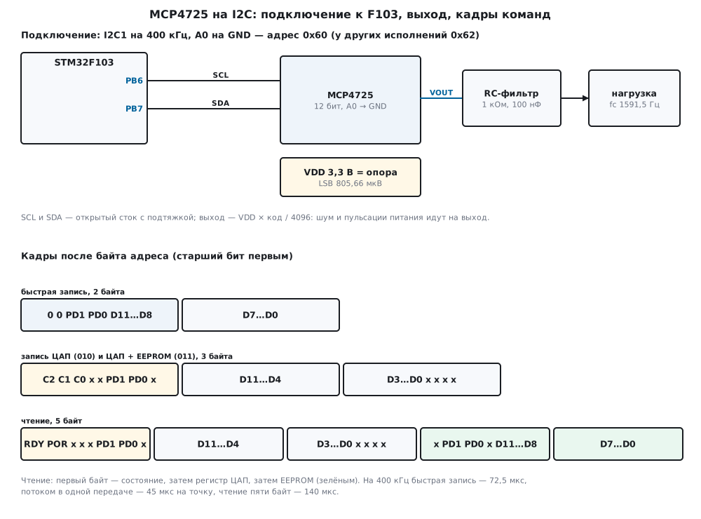
15в.2 Connecting it to the F103
| Module pin | STM32F103 | Purpose |
|---|---|---|
| SCL | PB6 | I2C1 clock |
| SDA | PB7 | I2C1 data |
| A0 | GND | lowest address bit: 0x60 |
| VDD, GND | 3.3 V and ground | supply and output reference |
| VOUT | load input | through an RC filter if a smooth signal is needed |
I2C1 is as in 15б.2: PB6 and PB7, 400 kHz, CCR = F/S | 30, TRISE =
11. Both pins are FT (DocID13587, p. 32), so a 5 V module with
pull-ups to 5 V will not burn them. The F1 cannot run I2C faster than 400 kHz:
RM0008 (p. 752) names only the standard mode up to 100 kHz and the fast mode
up to 400 kHz. The 3.4 MHz mode, which according to the manufacturer's documentation the
MCP4725 has, is not available from the F103.
The module supply is the reference. Putting it on the same 3.3 V as the microcontroller is simplest, but then the output carries all the digital noise. If precision matters, the MCP4725 is fed from a separate low-noise regulator with decoupling right at the VDD pin (15в.4).
The firmware finds the module by trying all eight addresses: in the model with A0
on ground and on the supply, for the A2 A1 = 00 and 01 versions, mcp_find found
0x60, 0x61, 0x62 and 0x63, while a direct probe of 0x60 on the last three returned
MCP_E_NACK.
15в.3 Commands: fast write, register write, five-byte read
There are no registers behind a pointer as in the ADS1115: the top bits of the first byte after the address say what to do. The fast write is two bytes, and it is the working command of the generator:
/* быстрая запись: 0 0 PD1 PD0 D11…D8, D7…D0 */
void mcp_fast_bytes(uint16_t code, uint32_t pd, uint8_t b[2])
{
    b[0] = (uint8_t)(MCP_CMD_FAST | (pd & 3u) << 4 | (code >> 8 & 0x0Fu));
    b[1] = (uint8_t)code;
}
Code 2048 gives the bytes 08 00, 4095 gives 0F FF, 2048 with shutdown through
1 kΩ gives 18 00, through 500 kΩ — 38 00. The Zephyr driver uses the same bit order.
The DAC register write (command 010) and the DAC with EEPROM write
(011) are three bytes, with the code shifted left by 4 bits:
/* запись регистра ЦАП (cmd = MCP_CMD_DAC) или ЦАП и EEPROM (MCP_CMD_DAC_EE): три байта */
static int write3(mcp_t *d, uint8_t cmd, uint16_t code, uint32_t pd)
{
    uint8_t b[3] = {(uint8_t)(cmd | (pd & 3u) << 1), (uint8_t)(code >> 4), (uint8_t)(code << 4)};
    if (code > MCP_MAX)
        return MCP_E_RANGE;
    int rc = xfer(d, b, 3, 0, 0);
    if (rc == MCP_OK) {
        d->code = code;
        d->pd = (uint8_t)(pd & 3u);
    }
    return rc;
}
In the model the code 2048 went out as the bytes 40 80 00, with EEPROM — 60 80 00.
The read is five bytes without a pointer: the status, the DAC register, the EEPROM.
/* пять байт: состояние (RDY, POR, PD), регистр ЦАП (D11…D4, D3…D0 xxxx), EEPROM (x PD1 PD0 x D11…D8, D7…D0) */
int mcp_read(mcp_t *d, mcp_status_t *s)
{
    uint8_t b[5];
    int rc = xfer(d, 0, 0, b, 5);
    if (rc)
        return rc;
    s->rdy = (uint8_t)(b[0] >> 7 & 1u);
    s->por = (uint8_t)(b[0] >> 6 & 1u);
    s->pd = (uint8_t)(b[0] >> 1 & 3u);
    s->code = (uint16_t)(b[1] << 4 | b[2] >> 4);
    s->ee_pd = (uint8_t)(b[3] >> 5 & 3u);
    s->ee_code = (uint16_t)((b[3] & 0x0Fu) << 8 | b[4]);
    return MCP_OK;
}
The first read in the model after power-up is C0 00 00 00 00: RDY = 1,
POR = 1, the output is on, the code is 0, the EEPROM holds 0 too (what a real chip has
from the factory was not checked). The F103 receives the five bytes with the
procedure for N > 2 (RM0008, p. 763): the last three go through BTF, and ACK
is cleared before the last but one.
What it costs on the bus (a byte is 9 clocks, start and stop one clock each):
| Command | SCL clocks | 100 kHz | 400 kHz | 3.4 MHz |
|---|---|---|---|---|
| fast write | 29 | 290 µs | 72.5 µs | 33.53 µs |
| DAC register write | 38 | 380 µs | 95 µs | 36.18 µs |
| five-byte read | 56 | 560 µs | 140 µs | 41.47 µs |
At 3.4 MHz every transfer by the I2C rules starts with a master code at 400 kHz — in the model 10 clocks, 25 µs — so a single write gets only twice as fast.
15в.4 Code to voltage: the step, the errors and the supply reference
The step is VDD / 4096. The conversion uses integers with rounding:
/* код → микровольты: VDD × код / 4096, опора — питание */
uint32_t mcp_code_uv(uint16_t code, uint32_t vdd_mv)
{
    return (uint32_t)(((uint64_t)code * vdd_mv * 1000u + 2048u) >> 12);
}
| VDD | Step | Code 1 | Code 2048 | Code 4095 |
|---|---|---|---|---|
| 3.3 V | 805.66 µV | 806 µV | 1 650 000 µV | 3 299 194 µV |
| 5 V | 1220.7 µV | 1221 µV | 2 500 000 µV | 4 998 779 µV |
Back with mcp_uv_code: 1 V at 3.3 V is code 1241, at 5 V — 819; 4 V at
3.3 V is impossible — the code hits 4095. The output falls short of VDD by exactly
one step.
Errors. A real DAC output differs from VDD × code / 4096: the offset shifts the whole line, the gain error changes the slope, INL is the bend of the line, DNL is unequal steps. There are no numbers from a document here; the model has an offset of −2 steps, a gain of −0.2 %, an INL bow of 1.5 steps and an error of its own for each code of 0.15 steps (RMS) — these are assumptions. What came out over all 4096 codes at 3.3 V:
- the three lowest codes give 0 V: the negative offset is cut off by ground;
- at code 2048 the error is −4.68 steps, the largest is 10.39 steps at code 4082;
- the largest step error (DNL) is 0.84 steps.
As with the ADC (14а.5), the offset and gain are removed by a two-point correction: measure the output at codes 256 and 3840 (in the model the errors are −2.112 and −9.239 steps) and recompute every code:
/* какой код записать, чтобы на выходе было напряжение кода want: c1 + ((want − c1) × 256 − e1) × span / den */
uint16_t mcp_cal_apply(const mcp_cal_t *c, uint16_t want)
{
    int64_t num = ((int64_t)((int32_t)want - c->c1) * 256 - c->e1_q8) * c->span;
    int64_t q = (num >= 0 ? num + c->den / 2 : num - c->den / 2) / c->den;
    int64_t r = c->c1 + q;
    return (uint16_t)(r < 0 ? 0 : r > (int64_t)MCP_MAX ? MCP_MAX : r);
}
For 1.65 V the correction writes 2054 instead of 2048. After it, over codes 64…4031 the error is no more than 2.11 steps (at code 1967): the INL bend and the steps remain, a straight line does not remove them.
The reference is the supply. This is the main difference from a DAC with an internal reference. Code 2048 at different VDD:
| VDD | Output | Error against 3.3 V | F103 ADC on the same supply |
|---|---|---|---|
| 3.3 V | 1650 mV | 0 | 2048 |
| 3.25 V | 1625 mV | −31 steps | 2048 |
| 3.2 V | 1600 mV | −62.1 steps | 2048 |
| 3.4 V | 1700 mV | 62.1 steps | 2048 |
A regulator that gave 3.25 instead of 3.3 V already means 31 steps of error, more than all the model errors together. And the supply ripple goes to the output in proportion to the code: 20 mV peak to peak on VDD gave at the output 0 mV at code 0, 5 mV at 1024, 10 mV at 2048 and 19.995 mV at 4095.
Two tricks follow. If the output is measured by the F103 ADC referenced to the same
supply, the error cancels — the last column of the table: the ratio of the
voltage to the supply does not depend on the supply. If absolute
volts are needed, the supply is measured (through VREFINT, 14.7) and the code recomputed,
or the MCP4725 is fed from a separate precise regulator.
15в.5 Speed and signal generation
The generator is the same one-period table as in 15.4, only each
point has to be carried over the bus. The driver builds the sine table with integers from
a quarter period (65 values), without sinf:
/* синус по 256-точечному кругу из четверти; n — степень двойки от 4 до 256 */
int mcp_table_sine(uint16_t *tab, uint32_t n, uint16_t mid, uint16_t amp)
{
    if (n < 4u || n > 256u || (n & (n - 1u)) || mid < amp || mid + amp > MCP_MAX)
        return MCP_E_RANGE;
    for (uint32_t i = 0; i < n; i++) {
        uint32_t j = i * (256u / n), r = j & 63u;
        int32_t s = (j & 64u) ? sin_q[64u - r] : sin_q[r];
        if (j & 128u)
            s = -s;
        int32_t v = (int32_t)amp * s;
        tab[i] = (uint16_t)(mid + (v >= 0 ? (v + 16384) >> 15 : -((-v + 16384) >> 15)));
    }
    return MCP_OK;
}
A sine of 32 points with the middle at 2048 and a swing of ±2000 starts with 2048, 2438, 2813, 3159, 3462, 3711, 3896, 4009 and runs from 48 to 4048; the triangle is 48, 298, 548, …, the saw 48, 177, 306, … within the same limits.
Two ways to push the points. From a timer: every point is its own transfer of 29 clocks. Streaming: one endless transfer, and according to the manufacturer's documentation the fast write byte pairs may follow one another without a new address — 18 clocks per point. The model ran both:
| Bus | Own transfer | points/s | Streaming | points/s | Sine 16 / 32 / 64 points, own transfer | same, streaming |
|---|---|---|---|---|---|---|
| 100 kHz | 290 µs | 3448 | 180 µs | 5556 | 215.5 / 107.8 / 53.9 Hz | 347.2 / 173.6 / 86.8 Hz |
| 400 kHz | 72.5 µs | 13 793 | 45 µs | 22 222 | 862.1 / 431 / 215.5 Hz | 1388.9 / 694.4 / 347.2 Hz |
| 3.4 MHz | 33.53 µs | 29 825 | 5.294 µs | 188 889 | 1864 / 932 / 466 Hz | 11 805.6 / 5902.8 / 2951.4 Hz |
This is the bus limit; the output settling time is not modelled, and at 3.4 MHz a point is shorter than a few microseconds, and whether the output keeps up with it was not checked. On the F103 the top two rows are real.
From a timer. TIM2 ticks at the point rate, its interrupt starts the transfer, the I2C1 interrupts do the rest:
void TIM2_IRQHandler(void)
{
    TIM2->SR = (uint16_t)~TIM_SR_UIF;
    if (busy) {                                         /* прошлая точка ещё на шине — эту пропускаем */
        overruns++;
        return;
    }
    mcp_fast_bytes(mcp_gen_next(&gen), MCP_PD_ON, frame);
    busy = 1;
    sent = 0;
    I2C1->CR2 |= I2C_CR2_ITEVTEN | I2C_CR2_ITBUFEN | I2C_CR2_ITERREN;
    I2C1->CR1 |= I2C_CR1_START;
}

void I2C1_EV_IRQHandler(void)
{
    uint16_t sr1 = I2C1->SR1;
    if (sr1 & I2C_SR1_SB) {
        I2C1->DR = (uint8_t)(dac.addr << 1);
    } else if (sr1 & I2C_SR1_ADDR) {
        (void)I2C1->SR2;
        I2C1->DR = frame[0];
        sent = 1;
    } else if ((sr1 & I2C_SR1_TXE) && sent == 1u) {
        I2C1->DR = frame[1];
        sent = 2;
        I2C1->CR2 &= (uint16_t)~I2C_CR2_ITBUFEN;        /* дальше нужен только BTF */
    } else if (sr1 & I2C_SR1_BTF) {
        I2C1->CR1 |= I2C_CR1_STOP;
        I2C1->CR2 &= (uint16_t)~(I2C_CR2_ITEVTEN | I2C_CR2_ITERREN);
        busy = 0;
    }
}
In the model, a sine of 32 points, 320 ticks:
| Bus | Tick | Expected | Skips | Got |
|---|---|---|---|---|
| 400 kHz | 100 µs | 312.5 Hz | 0 | 312.5 Hz |
| 400 kHz | 80 µs | 390.62 Hz | 0 | 390.62 Hz |
| 400 kHz | 70 µs | 446.43 Hz | 319 | 223.21 Hz |
| 100 kHz | 100 µs | 312.5 Hz | 319 | 104.17 Hz |
| 100 kHz | 300 µs | 104.17 Hz | 0 | 104.17 Hz |
The output changes 70 µs after the tick at 400 kHz (280 µs at 100 kHz)
— at the end of the second byte — but the delay is constant, and the frequency does not
depend on it. A tick shorter than the transfer — and every second point is skipped: a step of
140 µs instead of 70, half the frequency. The skips show nowhere except
the overruns counter.
Through DMA. The frames of the whole table — 64 bytes for 32 points — sit in
memory, DMA1 channel 6 (I2C1_TX, RM0008, p. 281) puts them into
I2C1->DR in a circle, and the transfer never ends. The processor is free, the frequency
is 400 kHz / 18 / 32 = 694.4 Hz, and the bus sets it, not a timer:
/* ── потоком: одна передача без конца, DMA1 канал 6 (I2C1_TX) по кругу ── */
static int gen_dma_start(void)
{
    int rc;
    uint32_t len = mcp_stream_frames(tab, GEN_N, stream_buf);
    RCC->AHBENR |= RCC_AHBENR_DMA1EN;
    DMA1_Channel6->CCR = 0;
    DMA1_Channel6->CPAR = (uint32_t)&I2C1->DR;
    DMA1_Channel6->CMAR = (uint32_t)stream_buf;
    DMA1_Channel6->CNDTR = len;
    DMA1_Channel6->CCR = DMA_CCR6_MINC | DMA_CCR6_CIRC | DMA_CCR6_DIR | DMA_CCR6_EN;   /* память → DR, по кругу */
    I2C1->CR2 |= I2C_CR2_DMAEN;                         /* до события ADDR: RM0008, с. 769 */
    if ((rc = start((uint8_t)(dac.addr << 1))) != MCP_OK)
        return fail(rc);
    (void)I2C1->SR2;                                    /* ADDR снят — дальше байты кладёт DMA */
    return MCP_OK;
}
The price is that the bus is taken forever: other devices on I2C1 get no room, and the frequency changes only with the number of points. Whether the F103 holds such a transfer for hours was not checked.
Spectrum and filter. The output is steps. The model assembled the output of a sine of 32 points at 10 kHz (312.5 Hz) with 64 samples per step, passed it through an RC filter and decomposed the last period with a fast Fourier transform. The spurs are "images" of the point rate: harmonics 31 and 33 (9687.5 and 10 312.5 Hz), 63 and 65:
| No filter | 1 kΩ, 100 nF (1591.5 Hz) | 3.3 kΩ, 100 nF (482.3 Hz) | |
|---|---|---|---|
| fundamental, amplitude | 1608.6 mV | 1578.46 mV | 1349.98 mV |
| harmonic 31 | −29.8 dB | −45.5 dB | −54.4 dB |
| harmonic 33 | −30.4 dB | −46.5 dB | −55.5 dB |
| harmonic 63 | −36 dB | −57.7 dB | −66.7 dB |
| everything except the fundamental | −24.9 dB | −42.6 dB | −51.5 dB |
Without a filter the amplitude of 1608.6 mV is almost exactly 2000 steps times 0.99839 (1608.74 mV): the step slightly weakens the fundamental too. A first-order filter suppresses the images by almost 16 dB, but the second variant already ate 16 % of the fundamental amplitude: the slope of a single RC is gentle (178.1), and it pays to take more points per period. With the model errors a second harmonic appeared from the INL bend: −70.1 dB without a filter, −70.6 and −72.9 dB with the filters, the third one is −88.2 dB. It is far below the images.
15в.6 EEPROM and power-down
The EEPROM keeps the code and the output mode while there is no power: at
power-up the chip according to the manufacturer's documentation loads them into the DAC
register. The write uses command 011 and takes long; while it runs, RDY in the
first read byte is 0. The driver polls it every 1000 µs for no
longer than 60 000 µs — as long as the Zephyr driver waits:
/* после записи EEPROM: опрашивать RDY, пока не станет 1 */
int mcp_wait_ready(mcp_t *d, uint32_t timeout_us)
{
    mcp_status_t s;
    for (uint32_t waited = 0;; waited += MCP_EE_POLL_US) {
        int rc = mcp_read(d, &s);
        if (rc)
            return rc;
        d->polls++;
        if (s.rdy)
            return MCP_OK;
        if (waited >= timeout_us)
            return MCP_E_TIMEOUT;
        mcp_port_delay_us(MCP_EE_POLL_US);
    }
}
| EEPROM write in the model | Polls | Time | Exchanges | Result |
|---|---|---|---|---|
| 25 ms | 23 | 25 315 µs | 24 | done |
| 50 ms | 45 | 50 395 µs | 46 | done |
| 70 ms | 61 | 68 635 µs | 62 | MCP_E_TIMEOUT |
25 and 50 ms are the limits from the Zephyr comment; 70 ms is a faulty chip, which the driver tells apart from a slow one. After writing 2048 to the EEPROM and a fast write of 100 the model's power was cycled: the DAC register is 2048 again, the output 1.6462 V — with the model errors.
Power-down. The PD1 PD0 bits switch off the output amplifier and pull the
output to ground through 1 kΩ (01), 100 kΩ (10) or 500 kΩ (11).
A free output is 0 V in any mode. The difference shows when there is a pull-up
outside: through 10 kΩ to 3.3 V the model gave 0.3, 3 and 3.235 V. The
five-byte read shows the mode (pd = 1, 2, 3), and the code stays —
3000. A fast write with PD = 00 brought the output back to 3000 codes, 2.4114 V.
The 1 kΩ mode holds the line at zero most reliably; 500 kΩ hardly
loads another source if the DAC output is in parallel with it.
15в.7 Pitfalls
Wrong address. A replacement module is silent at 0x60 — it is the
version with A2 A1 = 01 and the address 0x62 or 0x63. In the model a direct probe of
0x60 on such a module gives MCP_E_NACK, while the mcp_find search over 0x60…0x67
found it. The simplest is to search at every power-up — like
the bus scan from 17.7.
EEPROM in a loop. The value is written with command 011 on every change —
"so it remembers". Each write is 25 ms with waiting for RDY: in the model
20 writes took 506 300 µs, 25 315 µs each, 39.5 per second, while a
fast write takes 72.5 µs. The EEPROM endurance according to the manufacturer's documentation
is about a million writes (not checked); 1 000 000 writes at this
rate take 7.03 h. The firmware writes the EEPROM once, and only if
it holds a different value.
The reference wanders with the supply. 3.25 V instead of 3.3 is 31 steps of error at mid-scale; 20 mV of ripple is 10 mV at the output (15в.4).
Load. The output is not a power supply. An RC filter before a 10 kΩ load is a divider: the 1 kΩ of the filter and the 10 kΩ load left 0.909 of the signal. Drive the load through an op-amp (15.3).
5 V supply, pull-ups to 3.3 V. According to the manufacturer's documentation
the chip sees a one on SDA from 0.7 × VDD — at 5 V that is 3.5 V, and a
pull-up to 3.3 V does not reach it. In the model with this wiring
mcp_find found nothing, with pull-ups to 5 V it found 0x60. PB6 and PB7 are
FT, a pull-up to 5 V does not hurt them. One more thing: at 5 V the output is above 3.3 V
from code 2704 (3.3 / 5 × 4096 = 2703.36) — it cannot go to an F103 ADC input
like that.
A timer tick shorter than the transfer. 70 µs with 72.5 µs per point — every second point is skipped, 223.21 Hz came out instead of 446.43 Hz, and nothing outside shows it (15в.5).
15в.8 Summary
- The MCP4725 is 12 bits, one output, the supply as the reference: a step of 805.66 µV at 3.3 V and 1220.7 µV at 5 V; the address is 0x60 or 0x62 plus A0 — search for it by trying all.
- A fast write is 2 bytes, 72.5 µs at 400 kHz; a DAC register write is 95 µs; a five-byte read is 140 µs.
- A supply off by 50 mV is 31 steps at mid-scale; an ADC on the same supply does not see it, absolute volts need the supply measured.
- The two-point correction cut the model error from 10.39 to 2.11 steps.
- From a timer at 400 kHz — up to 13 793 points/s, a sine of 32 points is 431 Hz; streaming through DMA — 22 222 points/s, 694.4 Hz, but the bus is taken.
- The step images at 32 points are −29.8 dB; an RC of 1 kΩ, 100 nF gives −45.5 dB.
- EEPROM is 25 ms per write with waiting for
RDY, write it rarely; power-down pulls the output to ground through 1, 100 or 500 kΩ.
Full sources
mcp15d.h — addresses, commands, power-down modes, status bits, the port and the driver and generator functions.
/* mcp15d.h — раздел 15в: драйвер внешнего ЦАП MCP4725 по I2C и генератор сигнала без регистров микроконтроллера.
 * Драйвер говорит с микросхемой только через функции порта (mcp_port_*): в прошивке fw15d.c их делает I2C1
 * STM32F103, в стенде host15d.c — модель model15d.py.
 * Команды, форматы кадров, адреса, биты RDY и POR, режимы power-down — по документации производителя;
 * документа в проекте нет, с микросхемой не сверено (формат быстрой записи и чтение пяти байт с RDY
 * совпадают с драйвером dac_mcp4725 из Zephyr). */
#ifndef MCP15D_H
#define MCP15D_H
#include <stdint.h>

/* ── адрес: 1100 A2 A1 A0; A2 и A1 заданы при изготовлении, A0 — вывод ──────── */
#define MCP_ADDR_BASE     0x60u         /* A2 A1 = 00; у других исполнений 0x62, 0x64, 0x66 */
#define MCP_ADDR_LAST     0x67u

/* ── команды: старшие биты первого байта ───────────────────────────────── */
#define MCP_CMD_FAST      0x00u         /* 0 0 PD1 PD0 D11…D8, затем D7…D0 — два байта */
#define MCP_CMD_DAC       0x40u         /* 0 1 0 x x PD1 PD0 x, D11…D4, D3…D0 x x x x — три байта */
#define MCP_CMD_DAC_EE    0x60u         /* то же и запись в EEPROM: значение при включении */

/* ── power-down: что делает выход ──────────────────────────────────────── */
enum { MCP_PD_ON = 0, MCP_PD_1K = 1, MCP_PD_100K = 2, MCP_PD_500K = 3 };   /* 1, 100, 500 кОм на землю */

/* ── чтение пяти байт: состояние, регистр ЦАП, EEPROM ─────────────────── */
#define MCP_ST_RDY        0x80u         /* 1 — запись EEPROM закончена */
#define MCP_ST_POR        0x40u         /* 1 — питание в норме */

#define MCP_MAX           4095u
#define MCP_EE_POLL_US    1000u         /* шаг опроса RDY после записи EEPROM */
#define MCP_EE_TIMEOUT_US 60000u        /* столько же ждёт драйвер Zephyr */

enum { MCP_OK = 0, MCP_E_NACK = -1, MCP_E_BUS = -2, MCP_E_TIMEOUT = -3, MCP_E_RANGE = -4 };

typedef struct {
    uint8_t addr;                       /* семибитный адрес: 0x60…0x67 */
    uint8_t pd;                         /* последний записанный режим power-down */
    uint16_t code;                      /* последний записанный код */
    uint32_t xfers, errors, ee_writes, polls;
} mcp_t;

typedef struct {
    uint8_t rdy, por, pd, ee_pd;
    uint16_t code, ee_code;
} mcp_status_t;

/* поправка по двум точкам: ошибка e1, e2 (в единицах кода × 256) измерена на кодах c1 и c2 */
typedef struct {
    int32_t c1, e1_q8, span, den;
} mcp_cal_t;

/* генератор: таблица одного периода и номер следующей точки */
typedef struct {
    const uint16_t *tab;
    uint32_t n, i;
} mcp_gen_t;

/* ── порт: в прошивке — I2C1, в стенде — строки к модели ──────────────── */
/* записать ntx байт или прочитать nrx байт (MCP4725 читается без указателя); 0, MCP_E_NACK или MCP_E_BUS */
int mcp_port_xfer(uint8_t addr7, const uint8_t *tx, uint32_t ntx, uint8_t *rx, uint32_t nrx);
void mcp_port_delay_us(uint32_t us);

/* ── драйвер ──────────────────────────────────────────────────────────── */
void mcp_fast_bytes(uint16_t code, uint32_t pd, uint8_t b[2]);
int mcp_probe(mcp_t *d, uint8_t addr7);
int mcp_find(mcp_t *d);
int mcp_fast(mcp_t *d, uint16_t code, uint32_t pd);
int mcp_write_dac(mcp_t *d, uint16_t code, uint32_t pd);
int mcp_read(mcp_t *d, mcp_status_t *s);
int mcp_wait_ready(mcp_t *d, uint32_t timeout_us);
int mcp_write_eeprom(mcp_t *d, uint16_t code, uint32_t pd);
uint32_t mcp_code_uv(uint16_t code, uint32_t vdd_mv);
uint16_t mcp_uv_code(uint32_t uv, uint32_t vdd_mv);
void mcp_cal_two_point(mcp_cal_t *c, uint16_t c1, int32_t e1_q8, uint16_t c2, int32_t e2_q8);
uint16_t mcp_cal_apply(const mcp_cal_t *c, uint16_t code);

/* ── генератор ────────────────────────────────────────────────────────── */
int mcp_table_sine(uint16_t *tab, uint32_t n, uint16_t mid, uint16_t amp);
int mcp_table_triangle(uint16_t *tab, uint32_t n, uint16_t lo, uint16_t hi);
int mcp_table_saw(uint16_t *tab, uint32_t n, uint16_t lo, uint16_t hi);
uint16_t mcp_gen_next(mcp_gen_t *g);
uint32_t mcp_stream_frames(const uint16_t *tab, uint32_t n, uint8_t *buf);

#endif
mcp15d.c — driver: fast write, register and EEPROM write, five-byte read, correction, tables.
/* mcp15d.c — раздел 15в: драйвер MCP4725 по I2C и генератор по таблице. Один и тот же файл собирается в прошивку
 * (armclang, Cortex-M3) и в стенд на компьютере (gcc): микроконтроллера он не знает, только порт mcp_port_*. */
#include "mcp15d.h"

/* четверть периода синуса: round(32767 × sin(π/2 × i / 64)), i = 0…64 */
static const uint16_t sin_q[65] = {
    0, 804, 1608, 2410, 3212, 4011, 4808, 5602, 6393, 7179, 7962, 8739, 9512, 10278, 11039, 11793,
    12539, 13279, 14010, 14732, 15446, 16151, 16846, 17530, 18204, 18868, 19519, 20159, 20787, 21403, 22005, 22594,
    23170, 23731, 24279, 24811, 25329, 25832, 26319, 26790, 27245, 27683, 28105, 28510, 28898, 29268, 29621, 29956,
    30273, 30571, 30852, 31113, 31356, 31580, 31785, 31971, 32137, 32285, 32412, 32521, 32609, 32678, 32728, 32757,
    32767};

static int xfer(mcp_t *d, const uint8_t *tx, uint32_t ntx, uint8_t *rx, uint32_t nrx)
{
    int rc = mcp_port_xfer(d->addr, tx, ntx, rx, nrx);
    d->xfers++;
    if (rc)
        d->errors++;
    return rc;
}

/* быстрая запись: 0 0 PD1 PD0 D11…D8, D7…D0 */
void mcp_fast_bytes(uint16_t code, uint32_t pd, uint8_t b[2])
{
    b[0] = (uint8_t)(MCP_CMD_FAST | (pd & 3u) << 4 | (code >> 8 & 0x0Fu));
    b[1] = (uint8_t)code;
}

int mcp_fast(mcp_t *d, uint16_t code, uint32_t pd)
{
    uint8_t b[2];
    if (code > MCP_MAX)
        return MCP_E_RANGE;
    mcp_fast_bytes(code, pd, b);
    int rc = xfer(d, b, 2, 0, 0);
    if (rc == MCP_OK) {
        d->code = code;
        d->pd = (uint8_t)(pd & 3u);
    }
    return rc;
}

/* запись регистра ЦАП (cmd = MCP_CMD_DAC) или ЦАП и EEPROM (MCP_CMD_DAC_EE): три байта */
static int write3(mcp_t *d, uint8_t cmd, uint16_t code, uint32_t pd)
{
    uint8_t b[3] = {(uint8_t)(cmd | (pd & 3u) << 1), (uint8_t)(code >> 4), (uint8_t)(code << 4)};
    if (code > MCP_MAX)
        return MCP_E_RANGE;
    int rc = xfer(d, b, 3, 0, 0);
    if (rc == MCP_OK) {
        d->code = code;
        d->pd = (uint8_t)(pd & 3u);
    }
    return rc;
}

int mcp_write_dac(mcp_t *d, uint16_t code, uint32_t pd)
{
    return write3(d, MCP_CMD_DAC, code, pd);
}

/* пять байт: состояние (RDY, POR, PD), регистр ЦАП (D11…D4, D3…D0 xxxx), EEPROM (x PD1 PD0 x D11…D8, D7…D0) */
int mcp_read(mcp_t *d, mcp_status_t *s)
{
    uint8_t b[5];
    int rc = xfer(d, 0, 0, b, 5);
    if (rc)
        return rc;
    s->rdy = (uint8_t)(b[0] >> 7 & 1u);
    s->por = (uint8_t)(b[0] >> 6 & 1u);
    s->pd = (uint8_t)(b[0] >> 1 & 3u);
    s->code = (uint16_t)(b[1] << 4 | b[2] >> 4);
    s->ee_pd = (uint8_t)(b[3] >> 5 & 3u);
    s->ee_code = (uint16_t)((b[3] & 0x0Fu) << 8 | b[4]);
    return MCP_OK;
}

int mcp_probe(mcp_t *d, uint8_t addr7)
{
    mcp_status_t s;
    d->addr = addr7;
    d->xfers = d->errors = d->ee_writes = d->polls = 0;
    int rc = mcp_read(d, &s);                           /* ответил ли кто-то по этому адресу */
    if (rc == MCP_OK) {
        d->code = s.code;
        d->pd = s.pd;
    }
    return rc;
}

/* перебрать 0x60…0x67: A0 и заводские A2, A1 бывают разными */
int mcp_find(mcp_t *d)
{
    for (uint8_t a = MCP_ADDR_BASE; a <= MCP_ADDR_LAST; a++) {
        if (mcp_probe(d, a) == MCP_OK)
            return a;
    }
    return MCP_E_NACK;
}

/* после записи EEPROM: опрашивать RDY, пока не станет 1 */
int mcp_wait_ready(mcp_t *d, uint32_t timeout_us)
{
    mcp_status_t s;
    for (uint32_t waited = 0;; waited += MCP_EE_POLL_US) {
        int rc = mcp_read(d, &s);
        if (rc)
            return rc;
        d->polls++;
        if (s.rdy)
            return MCP_OK;
        if (waited >= timeout_us)
            return MCP_E_TIMEOUT;
        mcp_port_delay_us(MCP_EE_POLL_US);
    }
}

int mcp_write_eeprom(mcp_t *d, uint16_t code, uint32_t pd)
{
    int rc = write3(d, MCP_CMD_DAC_EE, code, pd);
    if (rc)
        return rc;
    d->ee_writes++;
    return mcp_wait_ready(d, MCP_EE_TIMEOUT_US);
}

/* код → микровольты: VDD × код / 4096, опора — питание */
uint32_t mcp_code_uv(uint16_t code, uint32_t vdd_mv)
{
    return (uint32_t)(((uint64_t)code * vdd_mv * 1000u + 2048u) >> 12);
}

uint16_t mcp_uv_code(uint32_t uv, uint32_t vdd_mv)
{
    uint64_t c = (((uint64_t)uv << 12) + vdd_mv * 500u) / (vdd_mv * 1000u);
    return (uint16_t)(c > MCP_MAX ? MCP_MAX : c);
}

/* ошибка выхода (в кодах × 256) измерена на кодах c1 и c2; считаем её прямой линией */
void mcp_cal_two_point(mcp_cal_t *c, uint16_t c1, int32_t e1_q8, uint16_t c2, int32_t e2_q8)
{
    c->c1 = c1;
    c->e1_q8 = e1_q8;
    c->span = (int32_t)c2 - (int32_t)c1;
    c->den = c->span * 256 + (e2_q8 - e1_q8);
}

/* какой код записать, чтобы на выходе было напряжение кода want: c1 + ((want − c1) × 256 − e1) × span / den */
uint16_t mcp_cal_apply(const mcp_cal_t *c, uint16_t want)
{
    int64_t num = ((int64_t)((int32_t)want - c->c1) * 256 - c->e1_q8) * c->span;
    int64_t q = (num >= 0 ? num + c->den / 2 : num - c->den / 2) / c->den;
    int64_t r = c->c1 + q;
    return (uint16_t)(r < 0 ? 0 : r > (int64_t)MCP_MAX ? MCP_MAX : r);
}

/* синус по 256-точечному кругу из четверти; n — степень двойки от 4 до 256 */
int mcp_table_sine(uint16_t *tab, uint32_t n, uint16_t mid, uint16_t amp)
{
    if (n < 4u || n > 256u || (n & (n - 1u)) || mid < amp || mid + amp > MCP_MAX)
        return MCP_E_RANGE;
    for (uint32_t i = 0; i < n; i++) {
        uint32_t j = i * (256u / n), r = j & 63u;
        int32_t s = (j & 64u) ? sin_q[64u - r] : sin_q[r];
        if (j & 128u)
            s = -s;
        int32_t v = (int32_t)amp * s;
        tab[i] = (uint16_t)(mid + (v >= 0 ? (v + 16384) >> 15 : -((-v + 16384) >> 15)));
    }
    return MCP_OK;
}

int mcp_table_triangle(uint16_t *tab, uint32_t n, uint16_t lo, uint16_t hi)
{
    if (n < 2u || (n & 1u) || lo > hi || hi > MCP_MAX)
        return MCP_E_RANGE;
    for (uint32_t i = 0; i < n; i++) {
        uint32_t k = i < n / 2u ? 2u * i : 2u * (n - i);         /* 0 … n … 0 */
        tab[i] = (uint16_t)(lo + ((hi - lo) * k + n / 2u) / n);
    }
    return MCP_OK;
}

int mcp_table_saw(uint16_t *tab, uint32_t n, uint16_t lo, uint16_t hi)
{
    if (n < 2u || lo > hi || hi > MCP_MAX)
        return MCP_E_RANGE;
    for (uint32_t i = 0; i < n; i++)
        tab[i] = (uint16_t)(lo + ((hi - lo) * i + (n - 1u) / 2u) / (n - 1u));
    return MCP_OK;
}

uint16_t mcp_gen_next(mcp_gen_t *g)
{
    uint16_t v = g->tab[g->i];
    if (++g->i >= g->n)
        g->i = 0;
    return v;
}

/* таблица → кадры быстрой записи подряд: 2 × n байт, для DMA по кругу в одной передаче */
uint32_t mcp_stream_frames(const uint16_t *tab, uint32_t n, uint8_t *buf)
{
    for (uint32_t i = 0; i < n; i++)
        mcp_fast_bytes(tab[i], MCP_PD_ON, &buf[2u * i]);
    return 2u * n;
}
fw15d.c — STM32F103 firmware: I2C1 at 400 kHz, the generator from TIM2 via interrupts or streaming through DMA.
/* fw15d.c — раздел 15в: MCP4725 на STM32F103 (BluePill), 72 МГц, APB1 = 36 МГц, таймеры APB1 — 72 МГц.
 * I2C1: PB6 — SCL, PB7 — SDA (открытый сток, 400 кГц). Вывод A0 модуля — на GND.
 * При включении: найти микросхему, записать в EEPROM код 0 — только если там другое. Затем синус 32 точки:
 * GEN_DMA = 0 — по таймеру TIM2 10 кГц, каждая точка своей передачей из прерываний I2C (312,5 Гц);
 * GEN_DMA = 1 — одна бесконечная передача, DMA1 канал 6 по кругу кладёт кадры в I2C1->DR (694,4 Гц).
 * Тактирование до 72 МГц — как в разделе 6. */
#include "stm32f10x.h"
#include "mcp15d.h"

#define CPU_HZ          72000000u
#define APB1_MHZ        36u
#define I2C_TIMEOUT_US  1000u
#ifndef GEN_DMA
#define GEN_DMA         0
#endif
#define GEN_N           32u
#define GEN_FS_HZ       10000u

static mcp_t dac;
static uint16_t tab[GEN_N];
static mcp_gen_t gen;
static uint8_t frame[2], stream_buf[2u * GEN_N];
static volatile uint8_t busy, sent;
volatile uint32_t overruns, bus_errors;

static int expired(uint32_t t0, uint32_t us)
{
    return DWT->CYCCNT - t0 >= us * (CPU_HZ / 1000000u);
}

void mcp_port_delay_us(uint32_t us)
{
    uint32_t t0 = DWT->CYCCNT;
    while (!expired(t0, us)) {
    }
}

static void i2c1_init(void)
{
    RCC->APB2ENR |= RCC_APB2ENR_IOPBEN | RCC_APB2ENR_AFIOEN;
    RCC->APB1ENR |= RCC_APB1ENR_I2C1EN;
    GPIOB->CRL = (GPIOB->CRL & 0x00FFFFFFu) | 0xFF000000u;    /* PB6, PB7 — альтернативная, открытый сток (1111) */
    I2C1->CR1 = 0;
    I2C1->CR2 = APB1_MHZ;
    I2C1->CCR = I2C_CCR_FS | 30u;                       /* DUTY = 0: 36 МГц / (3 × 30) = 400 кГц */
    I2C1->TRISE = APB1_MHZ * 300u / 1000u + 1u;         /* 11 */
    I2C1->CR1 = I2C_CR1_PE;
}

static int sr1_wait(uint16_t mask)
{
    uint32_t t0 = DWT->CYCCNT;
    while (!(I2C1->SR1 & mask)) {
        if (I2C1->SR1 & I2C_SR1_AF)
            return MCP_E_NACK;
        if (expired(t0, I2C_TIMEOUT_US))
            return MCP_E_BUS;
    }
    return MCP_OK;
}

static int fail(int rc)
{
    I2C1->CR1 |= I2C_CR1_STOP;
    I2C1->SR1 = (uint16_t)~I2C_SR1_AF;
    I2C1->CR1 &= (uint16_t)~I2C_CR1_ACK;
    return rc;
}

static int start(uint8_t addr_rw)
{
    int rc;
    I2C1->CR1 |= I2C_CR1_START;
    if ((rc = sr1_wait(I2C_SR1_SB)) != MCP_OK)
        return rc;
    I2C1->DR = addr_rw;
    return sr1_wait(I2C_SR1_ADDR);
}

/* запись ntx байт или чтение nrx ≥ 3 байт (RM0008, с. 763: три последних байта — через BTF) */
int mcp_port_xfer(uint8_t addr7, const uint8_t *tx, uint32_t ntx, uint8_t *rx, uint32_t nrx)
{
    int rc;
    uint32_t t0 = DWT->CYCCNT;
    if ((ntx && nrx) || (nrx && nrx < 3u))
        return MCP_E_BUS;
    while (I2C1->SR2 & I2C_SR2_BUSY) {
        if (expired(t0, I2C_TIMEOUT_US))
            return MCP_E_BUS;
    }
    if (ntx) {
        if ((rc = start((uint8_t)(addr7 << 1))) != MCP_OK)
            return fail(rc);
        (void)I2C1->SR2;
        for (uint32_t i = 0; i < ntx; i++) {
            if ((rc = sr1_wait(I2C_SR1_TXE)) != MCP_OK)
                return fail(rc);
            I2C1->DR = tx[i];
        }
        if ((rc = sr1_wait(I2C_SR1_BTF)) != MCP_OK)
            return fail(rc);
        I2C1->CR1 |= I2C_CR1_STOP;
        return MCP_OK;
    }
    I2C1->CR1 |= I2C_CR1_ACK;
    if ((rc = start((uint8_t)(addr7 << 1 | 1u))) != MCP_OK)
        return fail(rc);
    (void)I2C1->SR2;
    for (uint32_t i = 0; i + 3u < nrx; i++) {
        if ((rc = sr1_wait(I2C_SR1_RXNE)) != MCP_OK)
            return fail(rc);
        rx[i] = (uint8_t)I2C1->DR;
    }
    if ((rc = sr1_wait(I2C_SR1_BTF)) != MCP_OK)         /* N−2 в DR, N−1 в сдвиговом регистре */
        return fail(rc);
    I2C1->CR1 &= (uint16_t)~I2C_CR1_ACK;
    rx[nrx - 3u] = (uint8_t)I2C1->DR;
    if ((rc = sr1_wait(I2C_SR1_BTF)) != MCP_OK)
        return fail(rc);
    I2C1->CR1 |= I2C_CR1_STOP;
    rx[nrx - 2u] = (uint8_t)I2C1->DR;
    if ((rc = sr1_wait(I2C_SR1_RXNE)) != MCP_OK)
        return fail(rc);
    rx[nrx - 1u] = (uint8_t)I2C1->DR;
    return MCP_OK;
}

/* ── генератор по таймеру: TIM2 начинает передачу, прерывания I2C1 её ведут ── */
void TIM2_IRQHandler(void)
{
    TIM2->SR = (uint16_t)~TIM_SR_UIF;
    if (busy) {                                         /* прошлая точка ещё на шине — эту пропускаем */
        overruns++;
        return;
    }
    mcp_fast_bytes(mcp_gen_next(&gen), MCP_PD_ON, frame);
    busy = 1;
    sent = 0;
    I2C1->CR2 |= I2C_CR2_ITEVTEN | I2C_CR2_ITBUFEN | I2C_CR2_ITERREN;
    I2C1->CR1 |= I2C_CR1_START;
}

void I2C1_EV_IRQHandler(void)
{
    uint16_t sr1 = I2C1->SR1;
    if (sr1 & I2C_SR1_SB) {
        I2C1->DR = (uint8_t)(dac.addr << 1);
    } else if (sr1 & I2C_SR1_ADDR) {
        (void)I2C1->SR2;
        I2C1->DR = frame[0];
        sent = 1;
    } else if ((sr1 & I2C_SR1_TXE) && sent == 1u) {
        I2C1->DR = frame[1];
        sent = 2;
        I2C1->CR2 &= (uint16_t)~I2C_CR2_ITBUFEN;        /* дальше нужен только BTF */
    } else if (sr1 & I2C_SR1_BTF) {
        I2C1->CR1 |= I2C_CR1_STOP;
        I2C1->CR2 &= (uint16_t)~(I2C_CR2_ITEVTEN | I2C_CR2_ITERREN);
        busy = 0;
    }
}

void I2C1_ER_IRQHandler(void)
{
    I2C1->SR1 = 0;                                      /* AF, ARLO, BERR снимаются записью нуля */
    I2C1->CR1 |= I2C_CR1_STOP;
    I2C1->CR2 &= (uint16_t)~(I2C_CR2_ITEVTEN | I2C_CR2_ITBUFEN | I2C_CR2_ITERREN);
    bus_errors++;
    busy = 0;
}

static void gen_timer_start(uint32_t fs_hz)
{
    RCC->APB1ENR |= RCC_APB1ENR_TIM2EN;
    TIM2->PSC = CPU_HZ / 1000000u - 1u;                 /* 72 МГц → тик 1 мкс */
    TIM2->ARR = 1000000u / fs_hz - 1u;                  /* 10 кГц — каждые 100 мкс */
    TIM2->DIER = TIM_DIER_UIE;
    NVIC_SetPriority(I2C1_EV_IRQn, 0);
    NVIC_SetPriority(I2C1_ER_IRQn, 0);
    NVIC_SetPriority(TIM2_IRQn, 1);
    NVIC_EnableIRQ(I2C1_EV_IRQn);
    NVIC_EnableIRQ(I2C1_ER_IRQn);
    NVIC_EnableIRQ(TIM2_IRQn);
    TIM2->CR1 = TIM_CR1_CEN;
}

/* ── потоком: одна передача без конца, DMA1 канал 6 (I2C1_TX) по кругу ── */
static int gen_dma_start(void)
{
    int rc;
    uint32_t len = mcp_stream_frames(tab, GEN_N, stream_buf);
    RCC->AHBENR |= RCC_AHBENR_DMA1EN;
    DMA1_Channel6->CCR = 0;
    DMA1_Channel6->CPAR = (uint32_t)&I2C1->DR;
    DMA1_Channel6->CMAR = (uint32_t)stream_buf;
    DMA1_Channel6->CNDTR = len;
    DMA1_Channel6->CCR = DMA_CCR6_MINC | DMA_CCR6_CIRC | DMA_CCR6_DIR | DMA_CCR6_EN;   /* память → DR, по кругу */
    I2C1->CR2 |= I2C_CR2_DMAEN;                         /* до события ADDR: RM0008, с. 769 */
    if ((rc = start((uint8_t)(dac.addr << 1))) != MCP_OK)
        return fail(rc);
    (void)I2C1->SR2;                                    /* ADDR снят — дальше байты кладёт DMA */
    return MCP_OK;
}

int main(void)
{
    mcp_status_t st;
    CoreDebug->DEMCR |= CoreDebug_DEMCR_TRCENA_Msk;
    DWT->CYCCNT = 0;
    DWT->CTRL |= DWT_CTRL_CYCCNTENA_Msk;
    i2c1_init();
    while (mcp_find(&dac) < 0)
        mcp_port_delay_us(100000u);
    /* значение при включении — 0 В; EEPROM пишем, только если там другое: ресурс записи не бесконечен */
    if (mcp_read(&dac, &st) == MCP_OK && (st.ee_code != 0u || st.ee_pd != MCP_PD_ON))
        (void)mcp_write_eeprom(&dac, 0, MCP_PD_ON);
    (void)mcp_table_sine(tab, GEN_N, 2048, 2000);
    gen.tab = tab;
    gen.n = GEN_N;
    gen.i = 0;
    if (GEN_DMA)
        (void)gen_dma_start();
    else
        gen_timer_start(GEN_FS_HZ);
    for (;;)
        __WFI();
}
Next: section 16 "UART" — the very first interface people connect.