 Embedded HandbookApps
45. Touch input: TSC
A button with no mechanics: a copper pad under a plastic panel; a finger changes its capacitance by a few picofarads, and the controller notices it. No slots in the enclosure, no contacts that wear out — the device can be washed and wiped. The touch sensing controller (TSC) is a block that measures these picofarads in hardware, by charge transfer; this section explains how it does it, how to choose the external parts and the panel, how to get "pressed" out of a number, and what gets in the way.
The reference chip is the L476; the F072 and F303 have the same registers. The F1, F4 and G4 do not have the block.
What it is called in the documentation
Original Meaning touch sensing controller (TSC) the controller for touch buttons surface charge transfer acquisition measurement by charge transfer electrode, touchkey the electrode, the touch button sampling capacitor (Cs) the storage capacitor that collects the charge series resistor (Rs) the resistor in series with the pin overlay, front panel the panel over the electrodes sensitivity how strongly the count reacts to a finger reference, delta the reference value, the difference from it environment change system (ECS) tracking the environment: adjusting the reference detection time-out (DTO) the limit on how long a touch may last detection exclusion system (DXS) excluding simultaneous touches debounce suppressing bounce active (driven) shield an actively driven shield spread spectrum spreading the frequency spectrum linear / rotary sensor a slider / a wheel proximity detection without a touch
45.1 Who has it and what it gives
| Family | TSC | Groups × pins | Channels |
|---|---|---|---|
| F072 | yes | 8 × 4 | up to 24 (one pin in each group goes to the capacitor) |
| F303 | yes | 8 × 4 | up to 24 |
| L476 | yes | 8 × 4 | up to 24 |
| F103, F407, G474 | no | — | — |
The pin count is taken from the family headers; a specific package gives you part of them. Groups are measured in parallel, channels inside a group one after another: eight buttons on eight groups are measured in the time of one, the same eight buttons in three groups (3 + 3 + 2) in the time of three: in each group one pin is taken by the capacitor, so three channels remain.
Without the block you can repeat the same idea in software on any pins, but slower and noisier; for one or two buttons that works, for a panel it does not.
45.2 The principle: charge transfer
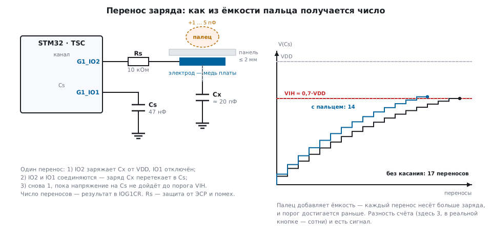
The electrode is a capacitor Cx between the copper and ground, about 20 pF; next to it on the board sits a storage capacitor Cs thousands of times larger. One controller cycle:
- the channel pin charges Cx from the supply, the Cs pin is disconnected;
- both pins are connected — the charge of Cx flows into Cs; the voltage on Cs rises by a small fraction;
- step 1 again — until the voltage on Cs reaches the input threshold VIH.
The number of cycles is the result. Each transfer raises the voltage on Cs by
the fraction Cx / (Cx + Cs) of the remaining way to VDD, so you
need roughly (Cs / Cx) · ln(1 / (1 − 0.7)) transfers with a threshold of 0.7·VDD.
A finger adds a few picofarads to Cx — the fraction grows, the threshold is reached
sooner, and the count goes down:
| Cs | Cx | Transfers | +1 pF | +2 pF | +5 pF | Time at 1.6 µs per transfer |
|---|---|---|---|---|---|---|
| 47 nF | 20 pF | 2830 | −134 | −257 (9 %) | −565 (20 %) | 4.5 ms |
| 10 nF | 20 pF | 603 | −55 | 1 ms | ||
| 100 nF | 20 pF | 6021 | 9.6 ms |
Two things follow from this. Sensitivity grows with Cs — more transfers, more resolution, but a longer measurement. And the signal is a difference (delta) between the reference count "nobody is touching" and the current one; the absolute number depends on the board, the panel and the temperature and means nothing by itself.
45.3 External parts and the panel
| Part | Value | Why |
|---|---|---|
| Cs | 47 nF (2.2…100); PPS, NPO, PET, PEN; not tantalum, X7R only for simple buttons | stability: dielectric absorption and the temperature drift of Cs turn directly into false touches |
| Rs | 10 kΩ (1…10), close to the MCU pin | protection against ESD and noise; the time constant Rs·Cx is 200 ns (Cx 20 pF), with a finger 250 ns; the charge phase is made no shorter than 3–5 such constants: in 800 ns the electrode charges to 96 % |
| a Schottky diode on the electrode | capacitance ≤ 2 pF | extra protection against harsh noise |
| panel | plastic up to 2 mm, glass is better (higher ε); no air gap, adhesive without bubbles | a gap of tenths of a millimetre kills sensitivity more than a millimetre of plastic |
| electrode | width at least four panel thicknesses (1.5 mm → 6 mm or more); the same shape for all buttons | equal Cx — common thresholds |
| gap between buttons | from 2 mm, better 4–5 | mutual influence |
| ground | hatched pour under the traces to the electrodes, not solid | solid ground adds to Cx and kills sensitivity |
| pins | for the TSC only, not shared with other functions; short traces, away from the regulator and PWM | pickup on the electrode is a false finger |
| an LED in the button | bypass with a 10 nF capacitor | otherwise the high-impedance LED circuit is an antenna |
45.4 Registers and one measurement cycle
The control register TSC_CR:
| Field | What it sets |
|---|---|
CTPH, CTPL |
the length of the charge phase and the transfer phase: 1…16 clocks (code + 1) |
PGPSC |
the HCLK divider for the pulse generator: 1…128 (2^code) |
MCV |
the count limit: 255…16383 (2^(8+code) − 1); on overflow, the MCEF flag |
SSE, SSD, SSPSC |
spread spectrum: enable, deviation (7 bits), prescaler |
IODEF |
unused group pins: 0 — pulled to ground, 1 — floating |
AM, SYNCPOL |
wait for an external sync pulse, and its edge |
START, TSCE |
start, enable |
The pins are described by four 32-bit registers (group × 4 + pin
number): IOCCR — which pins are channels, IOSCR — which go to Cs, IOHCR —
the Schmitt hysteresis on the pin (turn it off for TSC pins), IOASCR —
the analog switch (discharge). IOGCSR enables groups (bits 0…7) and
reports which ones have finished (bits 16…23); the result is in IOGxCR, 14 bits.
/* HCLK 80 МГц / 32 = 2,5 МГц; заряд 2 такта + перенос 2 такта = 1,6 мкс
   на перенос, 625 кГц. Предел 8191 переносов — 13 мс: если электрод
   оборван или закорочен, измерение всё равно закончится (флаг MCEF). */
static void tsc_init(void)
{
    RCC->AHB1ENR |= RCC_AHB1ENR_TSCEN;
    TSC->CR = (CYCLES(2u)       << TSC_CR_CTPH_Pos)
            | (CYCLES(2u)       << TSC_CR_CTPL_Pos)
            | (PGPSC_CODE(32u)  << TSC_CR_PGPSC_Pos)
            | (MCV_CODE(8191u)  << TSC_CR_MCV_Pos)
            | TSC_CR_TSCE;                         /* IODEF = 0: свободные выводы — в низкий уровень */
    TSC->IOHCR  &= ~(TSC_IOHCR_G1_IO1 | TSC_IOHCR_G1_IO2);   /* Шмитт выключить на выводах TSC */
    TSC->IOSCR   =  TSC_IOSCR_G1_IO1;              /* IO1 — конденсатор Cs */
    TSC->IOCCR   =  TSC_IOCCR_G1_IO2;              /* IO2 — электрод (канал) */
    TSC->IOGCSR  =  TSC_IOGCSR_G1E;                /* группу 1 — считать */
}

/* Одно измерение: пауза разряда, пуск, ожидание конца, число переносов. 0 — переполнение. */
static uint32_t tsc_measure(void)
{
    delay_us(TSC_DISCHARGE_US);                    /* разряд Cs: выводы прижаты к земле (IODEF = 0) */
    TSC->ICR = TSC_ICR_EOAIC | TSC_ICR_MCEIC;
    TSC->CR |= TSC_CR_START;
    while ((TSC->ISR & TSC_ISR_EOAF) == 0u) { }
    if (TSC->ISR & TSC_ISR_MCEF)
        return 0u;
    return TSC->IOGXCR[0] & TSC_IOGXCR_CNT_Msk;
}
The pause before the start is needed because Cs discharges only between
measurements, while the pins are pulled to ground (IODEF = 0). A function called
right after the previous one gives the discharge a few microseconds, and the leftover charge
shifts the count by an amount that depends on how often it is called. The pause is made
with margin and the same before every measurement: a pin pulled
to ground has tens of ohms, and Cs of 47 nF through 50 Ω discharges with a time
constant of 2.35 µs — after ten of them, 24 µs, less than a hundredth of a
percent of the charge remains; TSC_DISCHARGE_US = 100 covers this four times over.
delay_us is any pause in microseconds, even one on a timer (section 13).
The group pins are switched to the TSC alternate function (the Cs pin as
open-drain), and the measurement itself can be run on the EOAF interrupt
or with DMA — the controller needs no attention from the core while it counts.
Several buttons in one group mean several "banks": in each bank
IOCCR enables one channel per group, and the banks are measured one after
another. Three buttons per group — three measurements.
45.5 From a number to "pressed"
The raw count turns into an event through four mechanisms. They are not in the block but in the program, and without them the button does not work.
Reference and difference. The reference value is the count with the button released;
the difference is delta = ref − count. A touch only lowers the count, so
a negative difference is taken as zero.
Thresholds with hysteresis. The detect threshold is 55…65 % of the difference with a light touch, the release threshold is noticeably lower. For a response of 257 (+2 pF with Cs 47 nF) that is 154 and 90. Between them the button keeps its state — otherwise it bounces at the boundary.
Tracking the environment (ECS). Temperature, humidity and supply slowly
drift the count; the reference must follow them. A first-order filter:
ref += K · (count − ref), K = 1/64 — the reference catches up with a drift of 30 counts
in about a second (216 measurements of 4.5 ms), that is, clearly slower than
any touch. While the button is pressed, tracking is stopped, otherwise the reference
"eats" the finger.
Bounce and time-outs. Confirm the state with two or three measurements in a row; limit the length of a touch (DTO: a finger forgotten on the panel, or a book put on it — after a set time, recalibration); with several buttons allow only one pressed (DXS: a palm covered three — the strongest one counts).
#define DETECT_IN    50u        /* порог срабатывания — 55…65 % от отклика на палец */
#define DETECT_OUT   30u        /* порог отпускания — ниже: гистерезис */
#define ECS_SHIFT    6u         /* K = 1/64 — постоянная времени фильтра ~64 измерения */

static uint32_t ref_x64;        /* опора × 64: целочисленный фильтр без дробей */
static int      pressed;

static int touch_update(uint32_t count)
{
    uint32_t ref = ref_x64 >> ECS_SHIFT;
    uint32_t delta = (ref > count) ? ref - count : 0u;    /* нажатие — только уменьшение */

    if (!pressed && delta > DETECT_IN)  pressed = 1;
    if ( pressed && delta < DETECT_OUT) pressed = 0;
    if (!pressed)                                            /* опора подстраивается лишь в покое */
        ref_x64 += count - ref;
    return pressed;
}
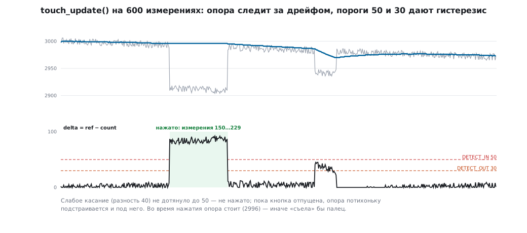
The thresholds 50 and 30 in the listing are for the synthetic run below (touches of −80
and −40); for a panel with a response of 257 you set 154 and 90. Before the loop the reference is set
by the first measurement: ref_x64 = count << ECS_SHIFT. If you start from zero, the reference
catches up with the count for about a second, and all that time the button does not fire.
The button states in a ready-made library are richer: released, proximity (a small difference — a hand is near), pressed, error (a count outside reason — an open or a short). Proximity is the same button with a lower threshold: light up the panel when a hand approaches.
The function above — unchanged — was run on a synthetic count (_verify/touch45/):
600 measurements, a slow reference drift of −30, a strong touch of −80 and a weak one of −40.
45.6 Noise and what to do about it
The weak spot of the method is noise at the transfer frequency and its harmonics (hundreds of kilohertz to tens of megahertz): mains switching supplies, backlight PWM, radio transmitters. The remedies, from simple to complex:
- larger Cs and Rs — slower, but more robust;
- spread spectrum (
SSE, deviationSSD) — the transfer frequency "jitters", and noise at a single frequency no longer coincides with it; the price is time: in a typical panel it adds about 2.6 ms to a measurement; - synchronisation (
AM,SYNCPOL) — measure on a pulse from the noise source, for example in the pause of the backlight PWM: the noise is always in the same phase and therefore becomes part of the reference; - active shield — a trace around the electrode driven by a dedicated group with its own Cs (100 nF) and Rs (1 kΩ) so that the voltage waveform on it repeats the electrode: the parasitic capacitance to ground disappears, the count doubles, and the noise on the traces does not;
- recalibration on noise — if the difference jumps around, keep measuring but disable detection until it settles.
The usual requirement for panel response is no worse than 20 ms to measure all buttons. Three channels of one group are measured one after another, and spread spectrum is added to each: 3 × (4.5 + 2.6) is 21 ms, already over the limit. Channels in different groups are measured at the same time: about 7 ms, with confirmation by two measurements 14 ms.
45.7 Slider, wheel, proximity
A slider is three or more electrodes in a row, each on its own channel; a finger over a joint changes the difference of two neighbours, and the position is obtained by weighting the differences: the "centre of gravity" across the channels. A wheel is the same in a ring. Slider electrodes are made toothed so that neighbours overlap and the difference changes smoothly. For such sensors Cs must be of stable dielectrics only (PPS, NPO, PET), because the position is computed from the absolute values of the differences, not from thresholds.
Proximity is a button with a large electrode and a low threshold: "a hand is near" centimetres before the touch.
45.8 The library and HAL
A ready-made touch sensing library is split into three layers: acquisition (TSC), processing (reference, differences, thresholds, ECS, DTO, DXS, debounce, slider position) and the application. Configuration is constants in one header: the number of channels, buttons, sliders, banks, thresholds, the coefficients K fast/slow, the ECS and DTO delays, debounce counters, the mode of free pins. Thresholds are chosen from a log of differences on the finished panel: the difference on touch is the base value, and 60 % of it is the detect threshold.
HAL describes the block with the TSC_InitTypeDef structure: CTPulseHighLength,
CTPulseLowLength, SpreadSpectrum (+ Deviation, Prescaler),
PulseGeneratorPrescaler, MaxCountValue, IODefaultMode,
SynchroPinPolarity, AcquisitionMode, ChannelIOs, SamplingIOs,
ShieldIOs. The cycle: HAL_TSC_IOConfig (bank), HAL_TSC_IODischarge,
HAL_TSC_Start or HAL_TSC_Start_IT, HAL_TSC_PollForAcquisition,
HAL_TSC_GroupGetStatus, HAL_TSC_GroupGetValue; the callback is
HAL_TSC_ConvCpltCallback.
Discharge before a measurement is mandatory: residual charge on Cs is
an offset of the count (the pause in tsc_measure, 45.4).
45.9 Battery power
The block needs HCLK; in Stop mode it does not count. The scheme for a battery device: sleep, wake up on a timer (section 10.6) every 50–100 ms, measure one "alarm-clock" button with a large electrode (proximity), go back to sleep. A full scan only when it has fired. Cs here must be of stable dielectrics only: between measurements the capacitor sits idle for a long time, and dielectric absorption shows more strongly.
45.10 Pitfalls
The count is always at the limit (MCEF). The electrode is open, the pin is not in
the alternate function, Cs is not connected or is too large for MCV:
220 nF with 20 pF is already beyond 8191.
The count is very small, the button is always "pressed". Cs is small or shorted; solid ground under the electrode; the Cs pin is not open-drain.
The button fires by itself as things warm up. The reference does not track the environment (no ECS) or Cs is X7R/tantalum. Use a reference filter and PPS/NPO.
The button "sticks". Environment tracking was not stopped during the touch and pulled the reference to the finger; there is no release threshold below the detect threshold.
False touches from the backlight or the charger. Noise at the transfer frequency: spread spectrum, synchronisation with the PWM, larger Rs.
It worked on the prototype, it does not work in the enclosure. An air gap under the panel; a thick panel with a small electrode (you need four thicknesses); adhesive with bubbles.
The neighbouring button fires too. A small gap between electrodes, shared traces, no DXS.
The Schmitt trigger on the pin is on. IOHCR — for TSC pins the bits
must be cleared, otherwise the threshold is wrong and the count jumps.
Different buttons — different sensitivity. Different electrode shapes or trace lengths; either make them the same, or give each its own threshold.
45.11 Summary
- The TSC is on F0, F3, L4 (8 groups × 4 pins, up to 24 channels); F1, F4, G4 do not have it.
- The method is charge transfer: the number of transfers to the threshold ≈ (Cs/Cx)·1.2; a finger lowers the count by a few percent; the signal is the difference from the reference.
- External parts: Cs 47 nF of a stable dielectric, Rs 10 kΩ at the pin, a panel without a gap, an electrode no narrower than four panel thicknesses, hatched ground.
- Registers:
CR(clocks, divider, limit, spectrum),IOCCR/IOSCR/IOHCR/IOGCSR, the result inIOGxCR; 2.5 MHz and 2+2 clocks give 1.6 µs per transfer, 4.5 ms per channel. - Processing is mandatory: a filtered reference, a threshold with hysteresis, confirmation, DTO, DXS — all of this is done by the library or by forty lines of your own code.
- Noise is cured with spread spectrum, synchronisation, an active shield and the external parts.
Next: section 46 "Special-purpose timers: HRTIM and LPTIM" — picoseconds for converters and PWM that runs while asleep.