 Embedded HandbookApps
46. Special-purpose timers: HRTIM and LPTIM
Two timers with opposite goals. HRTIM measures out hundreds of picoseconds — that is what you need to hold the output voltage of a switching converter to within fractions of a millivolt. LPTIM runs from 32768 Hz and draws fractions of a microampere — that is what you need to wake a device once a minute for a year on a single battery. All they have in common is the word "timer": neither replaces an ordinary one, and both solve a task where an ordinary one falls short.
Reference chips: G474 (HRTIM version two and LPTIM), F334 (HRTIM version one), L476 (LPTIM). The F103 and F407 have neither.
What it is called in the documentation
Original Meaning high-resolution timer (HRTIM) the timer with high time resolution low-power timer (LPTIM) the timer with low current consumption delay-locked loop (DLL) the delay line: it gives the fractions of a nanosecond prescaler ratio, multiplier the divider and multiplier of the counting frequency duty cycle the fraction of the period the output is on dead time the guard interval: both switches are off shoot-through current the current through both switches of a half-bridge complementary outputs a complementary pair of outputs break / fault input the emergency input burst mode PWM in bursts with a pause between them push-pull mode the two-phase push-pull mode one-shot / continuous a single run / continuous counting autoreload register (ARR) the reload register: sets the period pulse counter counting external pulses glitch filter a filter for short glitches on the input
46.1 Why yet another timer
An ordinary timer at 170 MHz with 100 kHz PWM fits 1700 steps into the period. That seems a lot — but in a 12 → 5 V buck converter one duty step becomes 7 mV at the output, and the duty closest to the required one misses by 2.4 mV. For an LED that does not matter; for a voltage regulator it is already noticeable.
HRTIM multiplies the counting frequency by 32: 5.44 GHz, a step of 184 ps, 54400 steps in the same period. The miss is 0.07 mV.
| Ordinary timer | HRTIM (×32) | |
|---|---|---|
| counting frequency at 170 MHz | 170 MHz | 5.44 GHz |
| step | 5.9 ns | 184 ps |
| steps in a 100 kHz period | 1700 | 54400 |
| duty step at a 12 V output | 7.06 mV | 0.22 mV |
| error in setting 5 V | 2.4 mV | 0.07 mV |
The second reason is not resolution but flexibility: in HRTIM the events "turn the output on" and "turn the output off" are set independently and chosen from a large set (period, four compares, external events, outputs of other timers). Hence phase shift, push-pull circuits and driving four switches with two channels — without a single processor instruction inside the period.
46.2 How HRTIM is built
Inside there is one master counter and six independent timers A…F (version one, F334, has five, A…E). Each has its own period, four compare registers, two outputs, its own dead time and its own binding to the fault inputs. The master sets the common period and synchronises the others.
/* Число таймеров различает версии блока. */
_Static_assert(sizeof(((HRTIM_TypeDef *)0)->sTimerxRegs) / sizeof(HRTIM_Timerx_TypeDef) == TIMERS_IN_HRTIM,
               "число независимых таймеров внутри HRTIM");
Counting frequency. The CK_PSC field is not just a divider: the low codes
multiply the frequency.
| Code | What it does | At 170 MHz | Step | PWM frequency range |
|---|---|---|---|---|
| 0 | ×32 | 5.44 GHz | 184 ps | 83 kHz … 57 MHz |
| 1…4 | ×16 … ×2 | 2.72 … 0.34 GHz | 0.37 … 2.9 ns | lower |
| 5 | as is | 170 MHz | 5.9 ns | 2.6 kHz … 57 MHz (at 3.5 MHz only 48 steps per period) |
| 6, 7 | ÷2, ÷4 | 85, 42.5 MHz | 12, 24 ns | from 649 Hz |
The upper and lower limits come from the same 16 bits of the counter: at ×32 a period of
65535 steps ends at 83 kHz; below that you need a smaller multiplier. From below,
the period must not be shorter than three clocks of the source frequency — that is 0x0060
at ×32, that is, about 57 MHz. This limit is the same for all codes: a smaller
multiplier only makes the step coarser.
Calibration. The fractions of a nanosecond come from the delay line, and its delay depends on temperature and supply. So it is calibrated before work, and then the calibration is repeated periodically:
HRTIM1->sCommonRegs.DLLCR = HRTIM_DLLCR_CAL | HRTIM_DLLCR_CALEN;
while ((HRTIM1->sCommonRegs.ISR & HRTIM_ISR_DLLRDY) == 0u) { }
Without this step the outputs work, but the promised resolution is not there — a typical mistake on the first start.
46.3 🔧 Buck converter: PWM, a pair of switches, fault
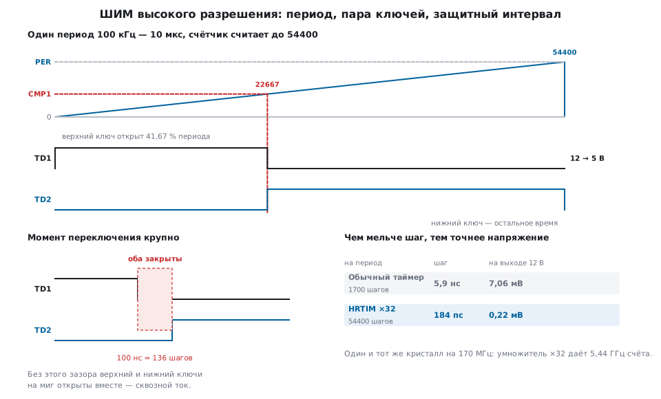
The task: 12 V in, 5 V out, 100 kHz, a synchronous rectifier — a second switch instead of the diode, so you need a complementary pair with dead time.
Period: 5.44 GHz / 100 kHz = 54400. Compare: 54400 × 5/12 = 22667.
#define TIMER_D   3u
static void hrtim_buck_setup(void)
{
    HRTIM_Timerx_TypeDef *td = &HRTIM1->sTimerxRegs[TIMER_D];

    RCC->APB2ENR |= RCC_APB2ENR_HRTIM1EN;

    /* Без готовой линии задержки разрешение не соблюдается. */
    HRTIM1->sCommonRegs.DLLCR = HRTIM_DLLCR_CAL | HRTIM_DLLCR_CALEN;
    while ((HRTIM1->sCommonRegs.ISR & HRTIM_ISR_DLLRDY) == 0u) { }

    td->TIMxCR = (CKPSC_MUL32 << HRTIM_TIMCR_CK_PSC_Pos)
               | HRTIM_TIMCR_CONT                     /* считать непрерывно */
               | HRTIM_TIMCR_PREEN                    /* период и сравнение — через тень */
               | HRTIM_TIMCR_TRSTU;                   /* тень → рабочий в начале каждого периода */
    td->PERxR  = PWM_PER;
    td->CMP1xR = PWM_CMP;
    HRTIM1->sCommonRegs.CR2 |= HRTIM_CR2_TDSWU;       /* первый перенос — программно */

    td->SETx1R = HRTIM_SET1R_PER;                     /* верхний ключ включается в начале периода */
    td->RSTx1R = HRTIM_RST1R_CMP1;                    /* и выключается по сравнению */

    /* Защитный интервал: второй выход получается сам, инверсией с задержкой. */
    td->DTxR   = (DT_STEPS << HRTIM_DTR_DTR_Pos)
               | (DT_STEPS << HRTIM_DTR_DTF_Pos);
    td->OUTxR  = HRTIM_OUTR_DTEN
               | (FAULT_HIGHZ << HRTIM_OUTR_FAULT1_Pos);

    /* Авария: вход FLT1 с фильтром, дальше — замок до сброса. */
    HRTIM1->sCommonRegs.FLTINR1 = HRTIM_FLTINR1_FLT1E
                                | (5u << HRTIM_FLTINR1_FLT1F_Pos)
                                | HRTIM_FLTINR1_FLT1LCK;
    td->FLTxR  = HRTIM_FLTR_FLT1EN | HRTIM_FLTR_FLTLCK;

    HRTIM1->sCommonRegs.OENR = HRTIM_OENR_TD1OEN | HRTIM_OENR_TD2OEN;
    HRTIM1->sMasterRegs.MCR |= HRTIM_MCR_TDCEN;       /* пуск */
}
Changing the voltage on the fly is one write: the shadow register is applied at
the start of the next period, and the waveform will not be torn in the middle of a pulse. The shadow
works only if an update source is enabled: here it is TRSTU —
the start of every period, and the first update is done by the program with the TDSWU bit
in CR2. Without them the active registers keep their reset values.
static void hrtim_set_duty(uint32_t vout_mv)
{
    HRTIM1->sTimerxRegs[TIMER_D].CMP1xR = (uint32_t)(((uint64_t)PWM_PER * vout_mv + VIN_MV / 2u) / VIN_MV);
}
Dead time. When DTEN is on, the second output is no longer
independent: it becomes the inverse of the first, shifted by a set
time. The delays on rising and falling edges are set separately (9
bits each), and the dead-time generator is clocked from fHRTIM × 8 = 1.36 GHz: a step of
0.735 ns, a maximum of 376 ns. A typical 100 ns is 136 steps and exactly one
percent of the period: that much duty is lost, and the
control loop must account for it.
Why the interval: half-bridge switches do not turn off instantly. If the low one turns on before the high one has turned off, a shoot-through current flows through both — tens of amperes straight from the supply rail to ground. That is not "gets a little warm", it is destruction of the switches within microseconds.
Fault. A comparator output or an external signal on the fault input
removes the PWM in hardware, without the core (section 44.7). What to do with the output
is set by the FAULT1 field: hold it active, make it inactive, release it to
the high-impedance state. The FLTLCK and FLT1LCK bits freeze
the configuration until reset — protection that cannot be turned off by accident.
46.4 What else HRTIM can do
Phase shift. Two timers with a common period and the compare shifted by half a period (27200 steps) give two PWM signals in antiphase. The phase step is 0.0066°. That is how two-phase converters are built: the current is split between two inductors, and the output ripple cancels out.
Buck-boost converter. Four switches, two timers: one works as the buck leg, the other as the boost leg. The circuit switches between modes on the fly, depending on whether the input voltage is above or below the output. Both legs have dead time, both listen to the fault input.
Burst mode. At light load a switching converter
is more efficient working in bursts: a few PWM periods, then a pause.
The block does this by itself, with the BMCR, BMPER, BMCMPR registers.
Triggering the ADC. HRTIM issues conversion triggers tied to the right place in the period: the inductor current is measured in the middle of the pulse, where it is not distorted by switching (section 14.5).
External events. Ten inputs, each of which can be routed to reset the counter, toggle an output, or a latch. A comparator, a sensor input, a signal from another timer — all of this changes the pulse shape without the program.
46.5 LPTIM: the timer that works while asleep
The opposite task. The device sleeps in Stop mode; everything clocked by the system frequency stands still. An ordinary timer stands still too. LPTIM does not: it takes its clock from LSE, LSI or straight from an external pin and keeps counting.
| TIM2 | LPTIM1 | |
|---|---|---|
| width | 32 bits | 16 bits |
| frequency | up to 170 MHz | 32768 Hz (LSE) |
| runs in Stop | no | yes |
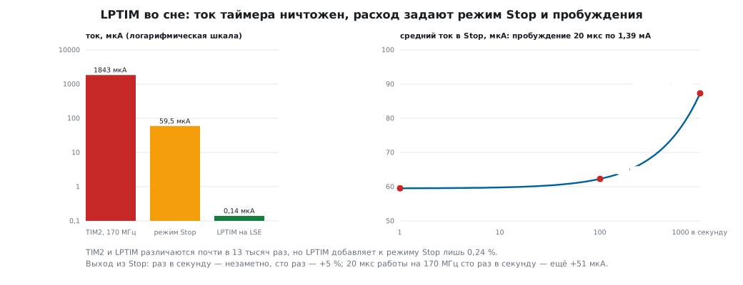
| consumption | 1843 µA at 170 MHz | 0.14 µA on LSE |
| channels | 4 | 1 |
The difference in consumption is almost 13 thousand times. But here comes a sober correction too: against the Stop 1 current of the G4 (about 60 µA at room temperature) the timer adds 0.24 % — that is, it is not the timer that determines battery drain, but the sleep mode and the wakeup rate. The exit from Stop itself — 1.39 mA for 20 µs — does not change the average current once a second, and a hundred times a second it adds 5 %. But after the exit the core runs, and that work is counted the same way: the run-mode current at the frequency the core runs at after wakeup, multiplied by the fraction of time awake. A G431 at 170 MHz draws 25.5 mA: 20 µs of work once a second adds 0.5 µA, a hundred times a second 51 µA, almost doubling the sleep current.
And Stop 1 of the G4 is itself too much for a battery: a year from a 220 mAh coin cell means an average current of no more than 25 µA, and with 59.5 µA of sleep it lasts 154 days. Battery families sleep deeper: on the L476, Stop 2 with the clock on LSE draws 1.67 µA, and the tenth of a microampere of the LPTIM itself is already about 6 % there.
Three uses.
The first is an alarm clock. Wake up once a second, measure, go back to sleep:
#define WAKE_S    1u
static void lptim_wakeup_1s(void)
{
    RCC->APB1ENR1 |= RCC_APB1ENR1_LPTIM1EN;
    RCC->CCIPR = (RCC->CCIPR & ~RCC_CCIPR_LPTIM1SEL_Msk)
               | (LPTIM1SEL_LSE << RCC_CCIPR_LPTIM1SEL_Pos);

    LPTIM1->CFGR = 0u;                       /* делитель 1, такты внутренние */
    LPTIM1->CR   = LPTIM_CR_ENABLE;          /* ARR пишут только у включённого блока */
    LPTIM1->ARR  = LSE_HZ * WAKE_S - 1u;     /* период = ARR + 1 отсчётов */
    while ((LPTIM1->ISR & LPTIM_ISR_ARROK) == 0u) { }   /* дождаться переноса в другой домен */
    LPTIM1->ICR  = LPTIM_ICR_ARROKCF;
    LPTIM1->IER  = LPTIM_IER_ARRMIE;
    LPTIM1->CR  |= LPTIM_CR_CNTSTRT;
    NVIC_EnableIRQ(LPTIM1_IRQn);
}
Limits: 16 bits from LSE give 2 seconds; with a divider of 128, 256 seconds. For longer, count wakeups in a variable or use the RTC (section 12.6).
The second is PWM that does not go out during sleep. A backlight, a buzzer, a heater: the core sleeps, the duty cycle holds.
static void lptim_pwm_in_stop(void)
{
    LPTIM1->CFGR = LPTIM_CFGR_PRELOAD;       /* обновлять ARR и CMP по концу периода */
    LPTIM1->CR   = LPTIM_CR_ENABLE;
    LPTIM1->ARR  = PWM_ARR;
    while ((LPTIM1->ISR & LPTIM_ISR_ARROK) == 0u) { }
    LPTIM1->CMP  = PWM_CMP_Q;
    while ((LPTIM1->ISR & LPTIM_ISR_CMPOK) == 0u) { }
    LPTIM1->ICR  = LPTIM_ICR_ARROKCF | LPTIM_ICR_CMPOKCF;
    LPTIM1->CR  |= LPTIM_CR_CNTSTRT;
}
ARR = 255 from LSE gives 128 Hz and a duty step of 0.39 % — coarse by
ordinary timer standards, but during sleep.
The third is a pulse counter. COUNTMODE switches the block to counting edges
from a pin, and the LSE clock is needed only by the digital filter: it compares
input samples and does not work without an internal clock. If you do not need the filter,
the block can be clocked directly by the input edges (CKSEL = 1, CKFLT = 0) —
then no oscillator runs at all, and bounce is suppressed with an RC network
(section 50.7). A flow meter, a turbine, a reed switch on a door — they count for years.
static void lptim_pulse_counter(void)
{
    RCC->CCIPR = (RCC->CCIPR & ~RCC_CCIPR_LPTIM1SEL_Msk)
               | (LPTIM1SEL_LSE << RCC_CCIPR_LPTIM1SEL_Pos);   /* окно фильтра отсчитывает LSE */
    LPTIM1->CFGR = LPTIM_CFGR_COUNTMODE                        /* фронты входа, CKSEL = 0 */
                 | (3u << LPTIM_CFGR_CKFLT_Pos);               /* фильтр от дребезга: 8 тактов LSE */
    LPTIM1->CR   = LPTIM_CR_ENABLE;
    LPTIM1->ARR  = 0xFFFFu;
    while ((LPTIM1->ISR & LPTIM_ISR_ARROK) == 0u) { }
    LPTIM1->CR  |= LPTIM_CR_CNTSTRT;
}
There is also an encoder mode (ENC) and a time-out mode (TIMOUT), where an external
event restarts the count: handy for catching "the signal has been gone for longer than".
46.6 Two LPTIM rules everyone trips over
The registers live in another clock domain. The core writes ARR and CMP at
the system frequency, but they operate at 32768 Hz. The transfer takes
several cycles of the slow clock and is confirmed by the ARROK and
CMPOK flags. Writing a second time without waiting for the flag loses the value.
And they can be written only while the block is enabled (ENABLE is already set).
The counter cannot be read with a single read. It ticks from a foreign clock, and a read can catch the moment of a transfer — you get a value that never existed. Read until two in a row match:
static uint32_t lptim_read_count(void)
{
    uint32_t a, b;
    do {
        a = LPTIM1->CNT;
        b = LPTIM1->CNT;
    } while (a != b);
    return a & LPTIM_CNT_CNT_Msk;
}
The same care is needed wherever a register is updated independently of the processor — it is a general property, not an LPTIM quirk.
46.7 HAL
| Function | What it does |
|---|---|
HAL_HRTIM_Init, HAL_HRTIM_DLLCalibrationStart |
basic setup and delay line calibration |
HAL_HRTIM_TimeBaseConfig |
multiplier, period, counting mode |
HAL_HRTIM_WaveformTimerConfig, HAL_HRTIM_WaveformOutputConfig |
what sets the waveform: set and reset events, polarity, fault behaviour |
HAL_HRTIM_WaveformCompareConfig |
compare registers |
HAL_HRTIM_TimerEventFilteringConfig, HAL_HRTIM_FaultConfig |
external events and fault inputs |
HAL_HRTIM_WaveformOutputStart, HAL_HRTIM_WaveformCountStart |
enable the outputs, start counting |
HAL_HRTIM_BurstModeConfig |
burst mode |
HAL_LPTIM_Init |
clock source, divider, trigger, filters |
HAL_LPTIM_PWM_Start, HAL_LPTIM_OnePulse_Start, HAL_LPTIM_TimeOut_Start_IT |
output modes |
HAL_LPTIM_Counter_Start_IT, HAL_LPTIM_Encoder_Start |
pulse counter, encoder |
HAL_LPTIM_ReadCounter |
reading the counter |
HRTIM is almost always configured with the project generator: the block has hundreds of fields, and the connected picture is easier to understand graphically than in a register table. But you still have to understand what exactly was generated — otherwise you cannot debug it.
46.8 Pitfalls
HRTIM: the resolution is not what was promised. The delay line calibration
was not done, or DLLRDY was not waited for.
HRTIM: a frequency below 83 kHz cannot be set. At ×32 the period does not fit into 16 bits. A smaller multiplier means a coarser step; that is the price.
HRTIM: the outputs are silent. They are not enabled in OENR, or the TD1/TD2 and
FLT1 pins are not switched to the HRTIM alternate function (the number is from the package pin
table), or counting is not started in MCR, or the block is held in fault — remove its cause first.
HRTIM: the switches get hot, the circuit sometimes blows up. There is no dead time, or it is shorter than the switch turn-off time. Check against the datasheet of the switch and the driver, with margin.
HRTIM: the duty "jumps" when changed on the fly. The shadow registers
(PREEN) are not enabled — the new value was applied in the middle of
a pulse.
HRTIM: the new period and compare are not applied. PREEN is on,
but no update source from the shadow is: neither TRSTU (on period), nor TREPU
(on repetition), nor the software bit in CR2.
F334 versus G4. Version one has five timers instead of six and a different clock source: there it is selected in RCC (the doubled PLL frequency or the bus clock), while on G4 the timer is clocked from the system frequency.
LPTIM: writing to ARR has no effect. The block is not enabled, or ARROK
was not waited for.
LPTIM: the counter shows nonsense. One read instead of two matching ones.
LPTIM: does not wake from Stop. The clock source is the bus frequency, not LSE or LSI: in Stop it stands still.
LPTIM: counts extra pulses. The filter (CKFLT) is not enabled, or
the contact bounces longer than its window. The filter works only from the internal
clock: with CKSEL = 1 there is none, and bounce is suppressed with an RC network.
The battery runs down faster than calculated. It is almost never the timer: look at the wakeup rate, the run time after wakeup and peripherals left enabled.
46.9 Summary
- HRTIM multiplies the counting frequency up to 5.44 GHz: a step of 184 ps, 32 times finer than an ordinary timer; the voltage setting error drops from millivolts to tenths of one.
- Six independent timers (version one has five), each with the output set and reset events assigned separately — hence phase shift, push-pull and bridge circuits.
- Dead time — a step of 0.735 ns, up to 376 ns; without it a half-bridge does not live long.
- The fault input removes the PWM in hardware, and the configuration can be frozen until reset.
- The delay line is calibrated before work and periodically — otherwise there is no resolution.
- LPTIM counts from LSE, LSI or an external pin and works in Stop: an alarm clock, PWM during sleep, a pulse counter.
ARRandCMPare written with the block enabled, and you wait forARROK/CMPOK; the counter is read twice until the values match.- The consumption of LPTIM itself is fractions of a microampere; battery drain is set not by it but by the sleep mode, the wakeup rate and the work after it. Stop 1 on the G4 (59.5 µA) keeps a coin cell going for 154 days; for a year you need the sleep of a family like L4 — Stop 2 with the clock on the L476 draws 1.67 µA.
Next: section 46а "CORDIC: sine, cosine and phase in a few clock cycles" — the G4 coprocessor for trigonometry in motor control.