 Embedded HandbookApps
96. Temperature: NTC thermistor and DS18B20
Temperature is most often measured in one of two ways: with a cheap thermistor through the ADC or with a DS18B20 digital sensor on a single wire. The first is analog: the accuracy depends on the divider, the ADC and how the code is converted to degrees. The second returns a number by itself, but brings a protocol with its own traps. This section covers both on the F103 and F407 with one goal: to get degrees as integers, without floating point.
The 1-Wire bus and its CRC are described in section 83.2, the ADC in section 14, and sensor wiring in general in section 95.
What it is called in the documentation
Original Meaning thermistor, NTC (negative temperature coefficient) a resistor whose resistance falls as temperature rises B value, beta the thermistor's B coefficient Steinhart–Hart equation a three-coefficient formula for the thermistor curve self-heating heating of the sensor by the measuring current ratiometric measurement a measurement where the supply cancels out scratchpad the sensor's working memory, 9 bytes conversion time (tCONV) the time one measurement takes parasite power power taken from the data line strong pull-up the line is held high by a switch ROM code, Skip ROM the sensor's 64-bit address; a command without an address
96.1 Two ways
| NTC thermistor | DS18B20 | |
|---|---|---|
| output | resistance → divider voltage | a number over the 1-Wire bus |
| needs from the STM32 | an ADC input | one pin and a UART or a timer |
| step | depends on temperature: 0.022 °C per code at 25 °C | 0.0625 °C at 12 bits |
| measurement time | microseconds | up to 750 ms at 12 bits |
| range | set by the table: here −40…+125 °C | −55…+125 °C |
| several sensors | one ADC input each | many on one wire |
| weak spot | converting the code to degrees, and self-heating | the protocol, and +85 °C before the first measurement |
96.2 NTC: divider and formula
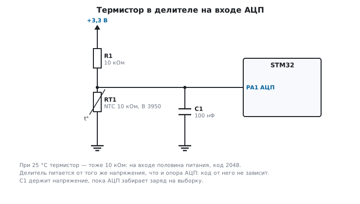
The resistance of an NTC thermistor falls as temperature rises:
R(T) = R25 · e^(B·(1/T − 1/T25)),
where T is in kelvins, R25 is the resistance at 25 °C (here 10 kΩ), and B is the coefficient from the documentation (here 3950). In a divider with a 10 kΩ resistor to the supply and the thermistor to ground, the ADC code equals 4095 · R / (R + 10 kΩ).
Two decisions in this circuit are not accidental:
- The fixed resistor equals R25. Then at 25 °C the input sits at exactly half the scale, code 2048, and that is exactly where the curve is steepest: the highest sensitivity falls at room temperature.
- The divider is powered from the same voltage as the ADC reference. The code is a ratio of resistances, and the supply cancels out (ratiometric measurement, section 81.2).
The 100 nF capacitor at the ADC input holds the voltage while the sampling capacitor takes its charge: for the ADC the divider is a source with an impedance of 5 kΩ (two 10 kΩ in parallel at 25 °C), and without the capacitor it would need a long sampling time (section 14.1).
96.3 Code → degrees as integers
A logarithm is expensive on the F103 with no floating-point unit, and it gives more accuracy than the thermistor itself does. It is simpler to use a table of codes every 5 °C and linear interpolation between the points:
static const uint16_t ntc_code[NTC_N] = {
    3996, 3955, 3900, 3830, 3740, 3629, 3495, 3337, 3156, 2955, 2738, 2510,
    2278, 2048, 1825, 1614, 1419, 1241, 1081,  940,  815,  707,  613,  532,
     462,  401,  350,  305,  267,  234,  206,  181,  160,  142,
};

int16_t ntc_dc(uint16_t code)
{
    if (code > ntc_code[0] || code < ntc_code[NTC_N - 1])
        return INT16_MIN;               /* обрыв, замыкание или вне −40…+125 °C */
    unsigned i = 0;
    while (code < ntc_code[i + 1])
        i++;
    int32_t span = ntc_code[i] - ntc_code[i + 1];
    int32_t part = ntc_code[i] - code;
    return (int16_t)((NTC_T0 + NTC_STEP * (int32_t)i) * 10 + (NTC_STEP * 10 * part + span / 2) / span);
}
The result is in tenths of a degree. A program on the computer went through all
codes from 142 to 3996 and compared the table with the exact formula: the largest
error is 0.203 °C, around −32 °C, where the curve bends most. A code beyond the
ends of the table is neither cold nor heat, but an open or a short circuit: the function
returns INT16_MIN, and you must not display that as a temperature.
How many degrees one code is worth depends on the temperature:
| Temperature | Codes per degree | Degrees per code |
|---|---|---|
| −20 °C | 19.98 | 0.050 |
| 25 °C | 45.49 | 0.022 |
| 100 °C | 7.08 | 0.141 |
The ADC step is not yet the accuracy: the thermistor itself, with its tolerance on resistance and on the B coefficient, has a larger error, and the single-B formula is an approximation. If you need better accuracy, use the manufacturer's table instead of the formula, or the Steinhart–Hart equation with three coefficients; the conversion function does not change, only the table does.
Self-heating. At 25 °C, 165 µA flows through the divider, and the thermistor dissipates 0.272 mW, so it heats itself. By how much: divide the power by the dissipation constant from the thermistor documentation: at 1–2 mW/°C this is 0.14–0.27 °C. If you measure once a second, it is better to power the divider from a port pin and turn it on only for the measurement. But after turn-on the 100 nF capacitor at the input charges through the divider: at 25 °C the time constant is 5 kΩ × 100 nF = 0.5 ms, and for the shortfall to code 2048 to become less than one code you need ln 2048 ≈ 7.6 time constants, 3.8 ms. At −40 °C the source impedance is almost 10 kΩ, and you have to wait 8.1 ms. Measure right away and the code is too low. Besides, a pin carrying 165 µA outputs slightly less than the supply: up to 8 mV, judging by the guarantee "0.4 V at 8 mA". That is 5 codes in the middle of the scale, a tenth of a degree.
96.4 DS18B20: how to ask for the temperature
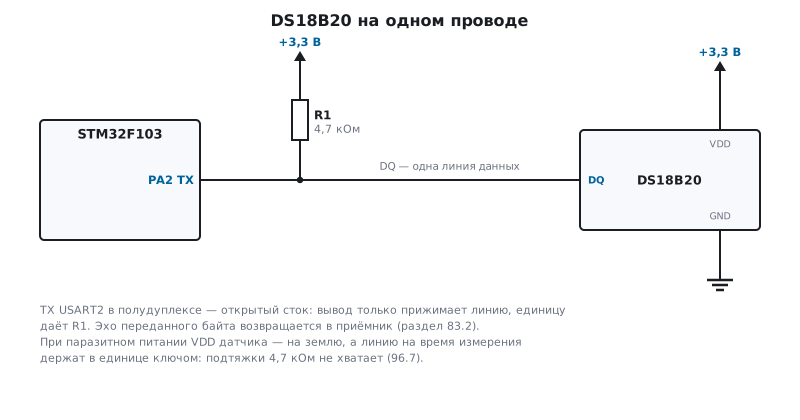
The sensor measures by itself and keeps the result in its 9-byte memory: the temperature (two bytes), the TH and TL thresholds, the configuration byte, reserved bytes and the CRC. A measurement takes two steps: "start" and, once it is done, "give me the memory":
int ds_start(void)
{
    if (!ow_reset())
        return 0;                       /* на шине никого */
    ow_write(DS_SKIP_ROM);
    ow_write(DS_CONVERT);
    return 1;
}

int ds_read(int32_t *mdeg, unsigned bits)
{
    uint8_t pad[9];
    if (!ow_reset())
        return 0;
    ow_write(DS_SKIP_ROM);
    ow_write(DS_READ_PAD);
    for (unsigned i = 0; i < 9; i++)
        pad[i] = ow_read();
    if (crc8_1wire(pad, 9) != 0)
        return 0;                       /* помеха на проводе */
    uint16_t raw = (uint16_t)(pad[0] | (pad[1] << 8));
    if (raw == DS_POWER_ON)
        return 0;                       /* измерения не было: сбой питания или прочли раньше срока */
    *mdeg = ds_mdeg(raw, bits);
    return 1;
}
ow_reset, ow_write and ow_read are the bus functions from section 83.2 (there
1-Wire is done on a UART in half-duplex, one byte per bit), and crc8_1wire comes from there too.
DS_SKIP_ROM addresses the sensor without naming its address, which is allowed only
when it is alone on the line. On the computer the driver worked with a sensor model:
ds_start sends 0xCC and 0x44, ds_read sends 0xCC and 0xBE, reads nine
bytes and returns 25.063 °C.
The measurement time depends on the resolution, and the resolution is set by two bits of the configuration byte:
| Resolution | Step | Configuration byte | Measurement time, max |
|---|---|---|---|
| 9 bits | 0.5 °C | 0x1F | 93.75 ms |
| 10 bits | 0.25 °C | 0x3F | 187.5 ms |
| 11 bits | 0.125 °C | 0x5F | 375 ms |
| 12 bits | 0.0625 °C | 0x7F | 750 ms |
#define DS_CONFIG(bits)   ((uint8_t)((((bits) - 9u) << 5) | 0x1Fu))
#define DS_TCONV_US(bits) (750000u >> (12u - (bits)))
96.5 Format: sixteenths of a degree
The temperature is a signed 16-bit two's complement number, with a unit of 1/16 °C:
| Temperature | Code |
|---|---|
| +125 °C | 0x07D0 |
| +85 °C | 0x0550 |
| +25.0625 °C | 0x0191 |
| +10.125 °C | 0x00A2 |
| +0.5 °C | 0x0008 |
| 0 °C | 0x0000 |
| −0.5 °C | 0xFFF8 |
| −10.125 °C | 0xFF5E |
| −25.0625 °C | 0xFE6F |
| −55 °C | 0xFC90 |
To get thousandths of a degree, multiply by 625 and divide by 10; at lower resolutions the low bits are undefined, and they are cleared:
int32_t ds_mdeg(uint16_t raw, unsigned bits)
{
    int32_t v = (int16_t)(raw & (uint16_t)~((1u << (12u - bits)) - 1u));
    return (v * 625 + (v < 0 ? -5 : 5)) / 10;
}
The cast to int16_t is mandatory: without it 0xFF5E would become +4085.875 °C
instead of −10.125. The code 0x0191 at 9 bits gives 25.000 °C: the three low bits
are discarded.
96.6 +85 °C is not a temperature
Right after power-up, the sensor memory looks like this:
50 05 4B 46 7F FF 0C 10 1C.
The temperature in it is 0x0550, exactly +85 °C, and the CRC of these nine bytes is correct: there is no noise, the sensor honestly returns what is in its memory. You read this if you read before the measurement finished, or if the sensor's supply dipped and it restarted. The CRC check does not catch this error, so the driver separately rejects exactly +85.000 °C.
If the device really does operate around +85 °C, this rule will not do: there you read strictly after the full measurement time, and remeasure on exactly +85.000.
96.7 Several sensors and parasite power
- Several sensors on one wire. Each has its own 64-bit address
(section 83.2). Instead of the command without an address, you send the command that addresses
by ROM, followed by the eight address bytes. "Start" can be sent to all of them at once with
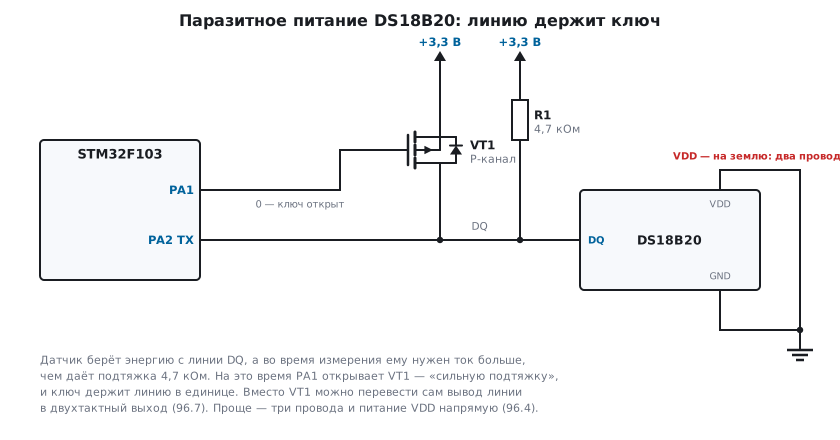
DS_SKIP_ROM: they measure simultaneously, and you then read them one by one. - Parasite power. The sensor can be connected with two wires: the supply pin to ground, and the energy from the data line through the pull-up. During a measurement it needs more current than a 4.7 kΩ pull-up provides, so for the whole measurement the line is held high by a switch, a "strong pull-up". The UART from section 83.2 cannot do this: its TX pin is open-drain. With parasite power you either switch the pin to push-pull output for the duration of the measurement, or fit a separate MOSFET. Simpler is three wires and power to the sensor directly.
96.8 Pitfalls
The thermistor shows −40 or +125 and does not change. The code went past the end of the table: an open circuit (code near 4095) or a short (near zero). Check for codes outside the table and do not pass them off as a temperature.
The thermistor reads "warmer" than the room. Self-heating by the divider current. Power the divider only for the measurement.
The thermistor readings drift with the supply. The divider is not powered from the ADC reference. Power it from the same voltage (section 81.2).
The DS18B20 returns +85 °C. It was read before the measurement finished, or the sensor restarted because of the supply. Wait the full measurement time; 85.000 after a reset is not a temperature.
Frost turns into thousands of degrees. The code was read as unsigned.
Cast it to int16_t.
The DS18B20 does not answer. There is no 4.7 kΩ pull-up, or the sensor is on parasite power without a strong pull-up during the measurement.
Two sensors on the line give garbage. They were addressed without an address, and both answered at once. Read by address.
96.9 Summary
- An NTC in a divider with a resistor equal to R25 gives half the scale at 25 °C and the highest sensitivity there too; the divider is powered from the ADC reference.
- Code to degrees: a table every 5 °C and integer interpolation, with an error of no more than 0.203 °C over the whole range of −40…+125 °C; a code beyond the end of the table is an open or a short circuit.
- The thermistor step is uneven: 0.022 °C per code at 25 °C and 0.141 °C at 100 °C.
- DS18B20: "start" (0xCC, 0x44), wait up to 750 ms, "give me the memory" (0xCC, 0xBE), check the CRC of the nine bytes.
- The temperature is 1/16 °C in two's complement; without the cast to
int16_tfrost becomes heat. - Exactly +85 °C with a correct CRC is the memory before the first measurement, not a temperature.
Next: section 97 "Humidity: DHT22, SHT31 and AHT20" — a single-wire protocol with pulse durations, and two I²C sensors with a CRC check.