 Embedded HandbookApps
97. Humidity: DHT22, SHT31 and AHT20
The three most common humidity sensors and two ways to talk to them. DHT22 has its own single-wire protocol where a bit is encoded by pulse width, and you have to measure it with a timer. SHT31 and AHT20 use the I²C bus and a reply protected by a CRC. All three also measure temperature, and from temperature and humidity you get the dew point — the moment the enclosure fogs up.
Pull-ups and wiring of the I²C bus are covered in section 95. The DHT single-wire protocol is not the 1-Wire of section 83.2: it has no addresses, and bits differ not by the moment of sampling but by pulse width.
Terms used in the documentation
Term Meaning relative humidity (RH) relative humidity dew point the temperature at which moisture condenses single-bus (proprietary) the DHT single-wire protocol — not 1-Wire pulse width the duration of a pulse checksum a check value — the sum of the bytes CRC-8, polynomial 0x31 CRC-8 with polynomial 0x31 single shot, repeatability one measurement on request; repeatability clock stretching the slave holds SCL low sign-magnitude sign and magnitude — not two's complement status byte, busy status byte; "still measuring"
97.1 Three sensors
| DHT22 | SHT31 | AHT20 | |
|---|---|---|---|
| interface | own single-wire | I²C, address 0x44 or 0x45 | I²C, address 0x38 |
| format | humidity and temperature, 16 bits each, in tenths | two 16-bit codes | two 20-bit codes |
| protection | sum of four bytes | CRC-8 on each word | CRC-8 on the whole reply |
| feature | a bit is a pulse width, poll no more often than once per 2 s | 16-bit commands | status byte: "still measuring" |
97.2 DHT22: a bit is a duration
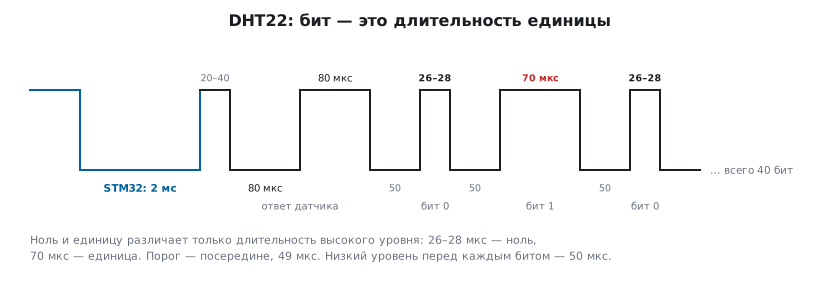
The STM32 pulls the line to ground for 2 ms — "start" (DHT11 needs at least 18 ms) — and releases it. The sensor responds: 80 µs low, 80 µs high, then 40 bits. Each bit is preceded by 50 µs low, and the bit itself is the width of the following high pulse: 26–28 µs is a zero, 70 µs is a one. So you measure the high pulses, and the threshold is in the middle, 49 µs.
DHT11 differs not only in the start: in its frame the bytes are integer and fractional parts
(humidity 2A 00 is 42 %, temperature 17 05 is 23.5 °C), not 16-bit numbers
in tenths. dht_decode below would give 1075.2 % for it — it needs its own parser.
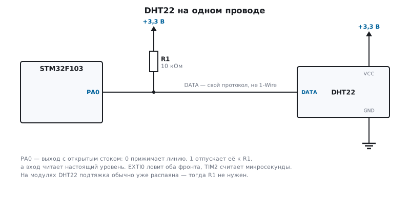
The easiest way is an interrupt on both edges and a timer counting microseconds:
on the rising edge store the time, on the falling edge record the width. TIM2 is clocked at
72 MHz on F103 and 84 MHz on F407 — a prescaler PSC of 71 and 83 gives 1 MHz. Pin
PA0 is an open-drain output: 0 pulls the line low, 1 releases it to the pull-up,
and IDR reads the real level, so you do not need to switch the direction.
void dht_start(void)
{
    pa0_open_drain();
    RCC->APB1ENR |= RCC_APB1ENR_TIM2EN;
    TIM2->PSC = TIM2_PSC;
    TIM2->ARR = 0xFFFFu;
    TIM2->EGR = TIM_EGR_UG;
    TIM2->CR1 = TIM_CR1_CEN;
    n_highs = 0;
    GPIOA->BSRR = GPIO_BSRR_BR0;        /* прижать линию: «начни» */
    uint16_t t0 = (uint16_t)TIM2->CNT;
    while ((uint16_t)(TIM2->CNT - t0) < 2000u) { }  /* 2 мс; DHT11 нужно не меньше 18 */
    EXTI->RTSR |= EXTI_RTSR_TR0;
    EXTI->FTSR |= EXTI_FTSR_TR0;
    EXTI->PR = EXTI_PR_PR0;
    EXTI->IMR |= EXTI_IMR_MR0;
    NVIC_EnableIRQ(EXTI0_IRQn);
    GPIOA->BSRR = GPIO_BSRR_BS0;        /* отпустить: дальше говорит датчик */
}

void EXTI0_IRQHandler(void)
{
    uint16_t now = (uint16_t)TIM2->CNT;
    if (GPIOA->IDR & 1u)
        rise_at = now;                  /* фронт — начало единицы */
    else if (n_highs < DHT_HIGHS)
        dht_high_us[n_highs++] = (uint16_t)(now - rise_at);    /* спад — её длительность */
    EXTI->PR = EXTI_PR_PR0;
}
There will be 42 falling edges: the first high pulse is the released line before the sensor responds, the second is the 80 µs response, and only from the third on come the 40 bits.
97.3 Decoding 40 bits and the sum
int dht_decode(const uint16_t hi_us[40], int16_t *t_dc, uint16_t *rh_dm)
{
    uint8_t b[5] = { 0 };
    for (unsigned i = 0; i < 40; i++)
        b[i / 8] = (uint8_t)((b[i / 8] << 1) | (hi_us[i] > DHT_BIT1_US));
    if ((uint8_t)(b[0] + b[1] + b[2] + b[3]) != b[4])
        return 0;                       /* сумма не сошлась */
    *rh_dm = (uint16_t)(b[0] << 8 | b[1]);
    int16_t t = (int16_t)((b[2] & 0x7F) << 8 | b[3]);
    *t_dc = (b[2] & 0x80) ? (int16_t)-t : t;    /* старший бит — знак, а не дополнительный код */
    return 1;
}
The five bytes of the frame 02 92 01 0D A2: humidity 0x0292 = 658 — 65.8 %,
temperature 0x010D = 269 — 26.9 °C, sum 0x02 + 0x92 + 0x01 + 0x0D = 0xA2.
A program on the PC built frames from pulses with jitter and passed
them to this function: the frame is decoded correctly even with pulses at the edges of tolerance —
36…38 and 58…60 µs, and a frame with a corrupted sum is rejected.
The sign is a separate bit. A negative temperature on the DHT22 is
the top bit plus the magnitude: code 0x8065 is −10.1 °C (the sum of such a frame is
0x79). Read as int16_t, the same code would give −32667, that is
−3266.7 °C. The DS18B20 (section 96) is the opposite, two's complement: one
and the same "wrong format" mistake gives different nonsense on the two sensors.
97.4 SHT31 and AHT20: CRC with polynomial 0x31
Both sensors append a CRC-8 to the data — with polynomial 0x31 and initial value 0xFF, most significant bit first:
uint8_t crc8_31(const uint8_t *p, size_t n)
{
    uint8_t crc = 0xFF;
    while (n--) {
        crc ^= *p++;
        for (int i = 0; i < 8; i++)
            crc = (uint8_t)((crc & 0x80) ? (crc << 1) ^ 0x31 : crc << 1);
    }
    return crc;
}
This is the same polynomial x⁸ + x⁵ + x⁴ + 1 as in 1-Wire (section 83.2): 0x8C there is 0x31 written backwards. But there the bits go least significant first and the computation starts from zero, so the result is different, and someone else's CRC function will not work here. The check value from the documentation: for bytes 0xBE 0xEF it is 0x92; the function gives it.
Addresses and commands:
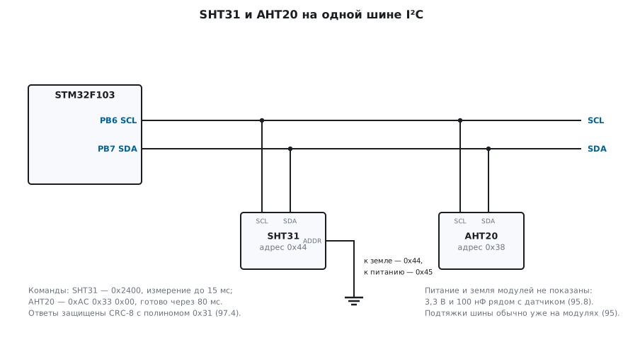
#define SHT31_ADDR     0x44u            /* 0x45, если вывод ADDR — к питанию */
#define SHT31_MEASURE  0x2400u          /* однократно, высокая повторяемость, без растягивания такта; до 15 мс */
#define AHT20_ADDR     0x38u
#define AHT20_TRIGGER  { 0xAC, 0x33, 0x00 }     /* начать измерение; готово через 80 мс */
Bus reads and writes are as in section 17: a command, a pause for the measurement,
a read of 6 bytes from the SHT31 and 7 bytes from the AHT20. Before the first AHT20 measurement,
40 ms after power-up, read the status byte: if bit 3 ("calibrated") is not
set, send 0xBE 0x08 0x00 and wait 10 ms.
97.5 Converting the codes
The SHT31 gives two 16-bit codes, each with its own CRC. Temperature is −45 + 175 · S / 65535 °C, humidity is 100 · S / 65535 %:
int sht31_convert(const uint8_t d[6], int16_t *t_c100, uint16_t *rh_c100)
{
    if (crc8_31(d, 2) != d[2] || crc8_31(d + 3, 2) != d[5])
        return 0;
    uint32_t st = (uint32_t)d[0] << 8 | d[1], srh = (uint32_t)d[3] << 8 | d[4];
    *t_c100 = (int16_t)((int32_t)((17500u * st + 32767u) / 65535u) - 4500);
    *rh_c100 = (uint16_t)((10000u * srh + 32767u) / 65535u);
    return 1;
}
Temperature code 0x6666 gives 25.00 °C, humidity code 0x8000 gives 50.00 %; their CRCs are 0x93 and 0xA2. One flipped bit — and the function rejects the reply.
The AHT20 gives 20-bit codes packed into five bytes after the status byte, and one CRC over all six. Humidity is S / 2²⁰ · 100 %, temperature is S / 2²⁰ · 200 − 50 °C:
int aht20_convert(const uint8_t d[7], int16_t *t_c100, uint16_t *rh_c100)
{
    if (d[0] & 0x80)
        return 0;                       /* ещё измеряет */
    if (crc8_31(d, 6) != d[6])
        return 0;
    uint32_t srh = (uint32_t)d[1] << 12 | (uint32_t)d[2] << 4 | d[3] >> 4;
    uint32_t st = ((uint32_t)d[3] & 0x0F) << 16 | (uint32_t)d[4] << 8 | d[5];
    *rh_c100 = (uint16_t)(((uint64_t)srh * 10000u + (1u << 19)) >> 20);
    *t_c100 = (int16_t)((int32_t)(((uint64_t)st * 20000u + (1u << 19)) >> 20) - 5000);
    return 1;
}
Humidity code 0x80000 is 50.00 %, temperature code 0x60000 is 25.00 °C, the reply CRC is 0x4E. The top bit of the status byte is "still measuring": such a reply is rejected and must be read again later.
97.6 Dew point
Relative humidity by itself tells a designer little. More important is the dew point — the temperature at which this air starts giving up water: if the enclosure or the board is colder, condensation forms on them. The Magnus formula over water:
double dew_point(double t_c, double rh)
{
    const double b = 17.62, c = 243.12;
    double g = log(rh / 100.0) + b * t_c / (c + t_c);
    return c * g / (b - g);
}
At 25 °C and 60 % the dew point is 16.69 °C, at 20 °C and 50 % it is 9.26 °C.
The F407 floating-point unit is single precision, so double there is still
computed in software; for once a second this does not matter, but for frequent computation
float and logf are better.
97.7 Pitfalls
The DHT22 is silent. The start pulse is shorter than needed (DHT11 needs at least 18 ms) or the sensor is polled more often than once per 2 s.
In frost the DHT22 shows thousands of degrees. Sign-magnitude was read as two's complement. The top bit is the sign.
The DHT22 sum sometimes does not match. Other interrupts delay the edge handler, and the widths drift. Give EXTI0 a high priority or capture the edges with a timer.
The SHT31 CRC never matches. The 1-Wire CRC function was used: the polynomial is the same, but the bit order and the initial value are different.
The AHT20 returns the same value. It was read before the measurement finished: the top bit of the status byte is "still measuring".
Humidity next to a hot board reads low. Relative humidity drops with heating: place the sensor away from the regulator and the processor.
97.8 Summary
- DHT22: a bit is the width of the high pulse (26–28 µs is a zero, 70 µs is a one), threshold 49 µs; measured with an interrupt on both edges and a 1 MHz timer.
- 40 bits — humidity, temperature and the sum; temperature is sign-magnitude: 0x8065 is −10.1 °C.
- SHT31 and AHT20 are protected by CRC-8 with polynomial 0x31 and initial value 0xFF: 0xBE 0xEF gives 0x92; 1-Wire has the same polynomial but a different bit order.
- SHT31: −45 + 175 · S / 65535 °C; AHT20 — 20-bit codes, S / 2²⁰ · 200 − 50 °C; check the "still measuring" bit.
- The dew point at 25 °C and 60 % is 16.69 °C: below that the enclosure fogs up.
Next: section 98 "Pressure and altitude: BMP280 and BME280" — calibration coefficients stored in the sensor itself and the compensation formulas.