 Embedded HandbookApps
163. Stability: phase margin, capacitive load, compensation
An amplifier that was calm on the bench rings on the board: a cable, a filter capacitor or an ADC input has been connected to its output. The cause is always the same — an extra delay has appeared in the feedback loop, and the phase margin has run out. This section is about how to calculate that margin, see it on a step and get it back.
Terms used in the documentation
Term Meaning loop gain gain around the whole feedback loop crossover frequency frequency where the loop gain falls to one phase margin phase reserve at crossover before the loop oscillates damping ratio how quickly oscillations of a second-order system die out overshoot how far a step response goes past its final value ringing decaying oscillation after a step second pole an additional pole that adds phase lag capacitive load a capacitance connected to the output isolation resistor a resistor that separates the output from a capacitive load feedback capacitor a capacitor across the feedback resistor input capacitance capacitance at the amplifier input open-loop output impedance output resistance of the amplifier without feedback
163.1 The loop and phase margin
The signal travels around the loop: the amplifier, the feedback network and back to the input.
The product of their gains is the loop gain T. Where |T|
falls to one is the loop crossover frequency. How much phase is left there before
−180° is the phase margin. At zero the loop becomes an oscillator; with a
small margin the circuit does not oscillate, but it rings.
An amplifier with a single crossover frequency already has −90° of phase by itself. A second pole
adds more: for a follower this is the output resistance of the amplifier
together with the load capacitance, fp = 1/(2π · Rout · C). At 50 Ω and
10 nF this is 318 kHz — below the loop crossover frequency, and the phase sags.
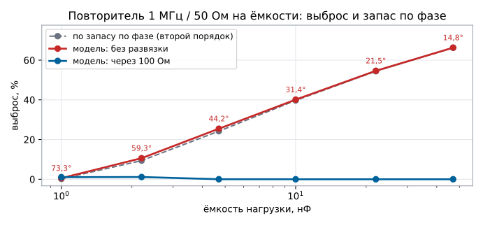
The phase margin converts into overshoot on a step — through a second-order system with the same margin. A follower with a gain-bandwidth product of 1 MHz and an output resistance of 50 Ω:
| Capacitance | Loop crossover | Phase margin | Overshoot from margin | Overshoot in model |
|---|---|---|---|---|
| 1 nF | 958 kHz | 73.3° | 0.2 % | 0.6 % |
| 2.2 nF | 860 kHz | 59.3° | 9.4 % | 10.6 % |
| 4.7 nF | 697 kHz | 44.2° | 24.2 % | 25.5 % |
| 10 nF | 521 kHz | 31.4° | 39.7 % | 40.1 % |
| 22 nF | 367 kHz | 21.5° | 54.4 % | 54.6 % |
| 47 nF | 256 kHz | 14.8° | 66.2 % | 66.3 % |
Two reference points are worth remembering: a 60° margin gives about 10 % overshoot, a 45° margin about 25 %.
163.2 How to measure the loop in a model
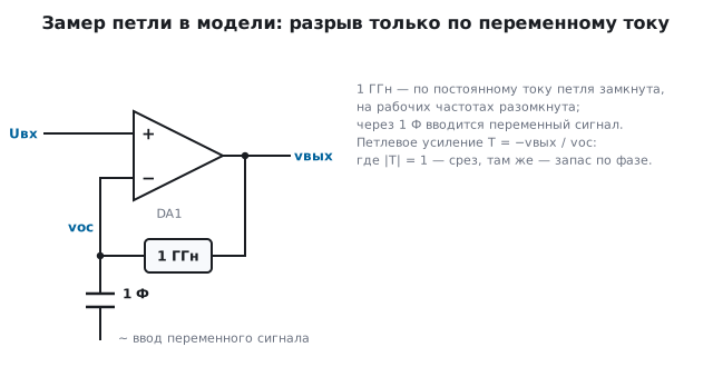
You cannot simply cut the loop: an amplifier without feedback goes into
saturation. The simulation trick is to open it for AC only:
an inductance of 1 GH is placed between the output and the feedback input
(the loop is closed for DC), and the AC signal is injected into the feedback input
through a 1 F capacitor. Then T = −vout / vfb.
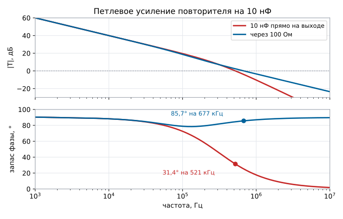
A measurement on the follower with 10 nF gives crossover at 521 kHz and a 31.4° margin — the same numbers as the calculation from the loop formula in 163.1.
163.3 The isolation resistor
A resistor of tens of ohms goes between the amplifier output and the capacitance, and the feedback is taken from the amplifier output, before the resistor. The capacitance no longer forms a pure pole with the output resistance: the resistor adds a zero, and the phase comes back.
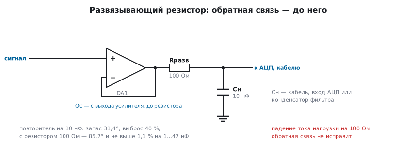
With a 100 Ω resistor the same follower on 10 nF has a margin of 85.7°, and over the whole range from 1 to 47 nF the overshoot is no more than 1.1 % — on the graph in 163.1 this is the bottom line.
The price is that the resistor is in series with the load: the load current makes a voltage drop across it that the feedback no longer corrects. For an ADC input or a cable to a high-impedance instrument this does not matter; for a load drawing a milliampere it is 0.1 V of error. If the error matters, the feedback is split in two: a resistor takes it after the isolation resistor, from the load itself — the DC voltage there is accurate — and a small capacitor feeds it from the amplifier output to its inverting input, so at high frequencies the loop does not see the capacitance.
163.4 Input capacitance and the feedback capacitor
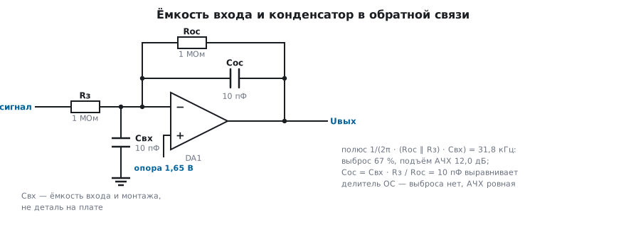
The second pole can also sit at the input. The capacitance of the inverting input
together with the wiring is a few picofarads, but with megohm resistors
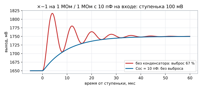
that is enough: for an inverting ×−1 on 1 MΩ / 1 MΩ with 10 pF at the input
the pole 1/(2π · (Rf ∥ Rg) · Cin) = 1/(2π · 500 kΩ · 10 pF) is 31.8 kHz.
Model: 67 % overshoot on a step and a peak in the magnitude response of 12.0 dB at
123 kHz. The cure is a capacitor across Rf, Cf = Cin · Rg / Rf,
here 10 pF: the feedback divider becomes the same at all
frequencies. With it there is no overshoot, and the magnitude response is flat.
The same leads to a rule: high-impedance feedback almost always needs a capacitor. Megohms are used only where you cannot do without them — a photodiode transimpedance amplifier, a piezo sensor.
163.5 Pitfalls
The follower rings after a cable is connected. The cable capacitance together with the amplifier output resistance ate the phase margin — an isolation resistor is needed.
A capacitor was added at the output "for filtering", and it got worse. The same mechanism; the filter goes after the isolation resistor.
Ringing appeared only on the board. Stray capacitance at the inverting input with high-impedance feedback — a capacitor across Rf.
The circuit is stable at ×10 but rings as a follower. The follower is the hardest case: the whole loop without attenuation; the documentation states whether the amplifier is unity-gain stable (×1).
The isolation resistor spoiled the accuracy. The load current drops across it, and the feedback is taken before it.
163.6 Summary
- Phase margin is how much phase is left before −180° at the loop crossover frequency; 60° gives about 10 % overshoot, 45° about 25 %.
- A 1 MHz, 50 Ω follower on 10 nF: second pole at 318 kHz, loop crossover at 521 kHz, 31.4° margin, 40.1 % overshoot in the model.
- A 100 Ω resistor with the feedback taken before it raises the margin to 85.7° and keeps the overshoot at no more than 1.1 % for capacitances of 1…47 nF.
- 10 pF at the input with 1 MΩ / 1 MΩ gives a pole at 31.8 kHz, 67 % overshoot and a 12.0 dB peak; a 10 pF feedback capacitor removes both.
Next: section 164 "Real op-amp parameters".