 Embedded HandbookApps
12. Service blocks: watchdog timers, CRC, RTC
Three blocks that are rarely covered in detail, but without which a serious product does not ship: a watchdog that restarts a hung program, a data integrity check and a clock that keeps running with the power removed.
Terms used in the documentation
Term Meaning independent watchdog the watchdog with its own clock window watchdog the watchdog with a refresh window to refresh / kick / feed to reload the counter, "feed" the watchdog reload value the value the counter is reloaded with reset flag the flag showing the reset cause cyclic redundancy check a checksum computed by polynomial division backup domain the part that runs from the battery prescaler the input divider refresh window the interval in which feeding is allowed early wakeup interrupt (EWI) an early interrupt before the reset reset pulse on NRST a reset pulse on the NRST pin alarm the clock alarm alarm mask an alarm mask: the field is not compared binary-coded decimal (BCD) each decimal digit in four bits write protection key the key that removes write protection configuration mode (CNF) the RTC register configuration mode
12.1 Why a watchdog timer
A program can hang: an endless loop waiting for a flag that never comes, a corrupted pointer, noise on a bus. In the lab you press reset, but a product in the field must restart by itself.
A watchdog timer is a counter that continuously counts down and, on reaching zero, resets the chip. The program must reload it regularly ("feed" it). If it stops feeding, it has hung, and the restart happens by itself.
The STM32 has two such timers, and they solve different tasks.
12.2 IWDG: independent
It is clocked from its own LSI oscillator and works even if the rest of the clock system has stopped. This is exactly what makes it reliable: a failure of the PLL or the crystal does not affect it.
#define IWDG_KEY_RELOAD   0xAAAAu   /* перезагрузить счётчик */
#define IWDG_KEY_ENABLE   0xCCCCu   /* запустить */
#define IWDG_KEY_UNLOCK   0x5555u   /* открыть доступ к настройкам */

void iwdg_start_2s(void)
{
    IWDG->KR = IWDG_KEY_ENABLE;      /* пошёл; заодно включает LSI */
    IWDG->KR = IWDG_KEY_UNLOCK;      /* снять защиту записи */
    IWDG->PR = IWDG_PR_PR_2;         /* 100b -> делитель 64 */
    IWDG->RLR = 1250u;               /* значение перезагрузки */

    while (IWDG->SR) { }             /* дождаться применения настроек — нужен идущий LSI */

    IWDG->KR = IWDG_KEY_RELOAD;
}

void iwdg_feed(void)
{
    IWDG->KR = IWDG_KEY_RELOAD;
}
The order matters. New PR and RLR values reach the counter within a few
LSI cycles, and the flags in SR clear only while the oscillator is running. The key
0xCCCC switches LSI on by itself, so the watchdog is started first: if you wait for
SR before that, and nobody had switched LSI on, the loop never ends.
Until setup is complete the watchdog counts with the values present after reset —
divider 4 and 4095, on the F1 that is 4096 × 4 / 40000 ≈ 0.4 seconds; that is more than enough
to write two registers.
Timeout calculation:
таймаут = (RLR + 1) × предделитель / частота LSI
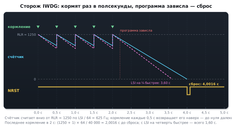
        = (1250 + 1) × 64 / 40000 ≈ 2 секунды
The prescaler is set by three bits: 000 is division by 4, each next step
doubles it, up to 256. The reload counter is 12-bit, maximum 4095. Hence
the maximum timeout: 4096 × 256 / 40000 ≈ 26 seconds.
The LSI frequency depends on the family. On the F1 the nominal is 40 kHz, on the F4 and F7 it is
32 kHz: the same code gives there (1250 + 1) × 64 / 32000 ≈ 2.5 seconds
instead of two, and the limit is 4096 × 256 / 32000 ≈ 32.8 seconds against 26.2.
And you must not count by the nominal: if the oscillator turns out a quarter
faster, the two-second timeout becomes 1.6 seconds — the watchdog must be fed
based on the shortest timeout.
What it looks like over time — the watchdog counter, feeding and the reset after a hang:
⚠️ LSI is inaccurate. Its frequency wanders by tens of percent depending on temperature and the individual chip. You cannot calculate the timeout with no margin: if the calculation gives 2 seconds, feed it at least once every half second. The exact spread limits are in the datasheet, in the electrical characteristics section.
⚠️ A running IWDG cannot be switched off. Not by software, not in any other way — only by a chip reset. This is intentional: faulty code must not be able to disable the watchdog.
12.3 WWDG: window
The second watchdog is more cunning. It complains not only about late feeding, but also about feeding too early: there is a window inside which the counter may be refreshed, and outside it — reset.
Why this way: if the program has fallen into a loop that happens to pass the "feed" call more often than it should, an ordinary watchdog will not notice. The window one will, because the expected rhythm is broken.
The WWDG is clocked from the APB1 bus, so it stops together with it and is suited more to monitoring the timing of the program than to protection against a complete hang. In practice the IWDG is used more often, and the window one is used where it is important to prove the rhythm is kept — for example, in products undergoing functional safety certification.
How to calculate. The counter is 7-bit and is clocked from PCLK1 through a divider of 4096
and a further 2^WDGTB. The reset happens when bit T6 drops, that is, the counter
goes from 0x40 to 0x3F, or when it is fed while the counter is above the window W.
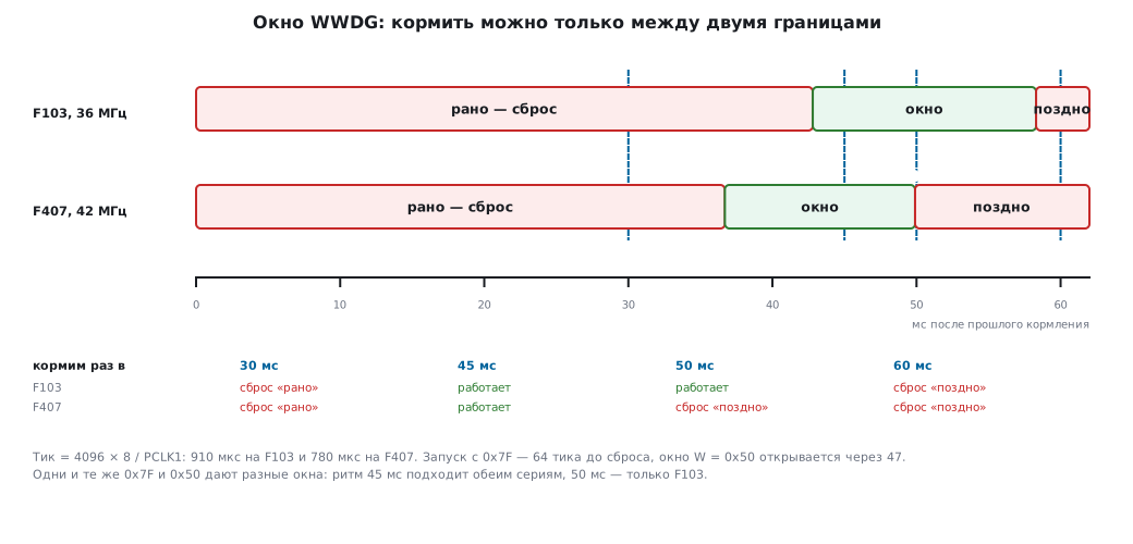
It is started from 0x7F: 64 ticks until reset.
| F103, PCLK1 36 MHz | F407, PCLK1 42 MHz | |
|---|---|---|
tick with WDGTB = 3 (÷8) |
4096 × 8 / 36 MHz = 910 µs | 4096 × 8 / 42 MHz = 780 µs |
| from 0x7F to reset — 64 ticks | 58.3 ms | 49.9 ms |
window W = 0x50 opens after 47 ticks |
42.8 ms | 36.7 ms |
Feed between these limits: on the F103 from 42.8 to 58.3 ms after the previous time, on the F407 from 36.7 to 49.9 ms. A 45 ms rhythm suits both.
#define WWDG_T0 0x7Fu                   /* с чего считать: до сброса 64 тика */
#define WWDG_W  0x50u                   /* кормить можно, когда счётчик ≤ 0x50 */

void wwdg_start(void)
{
    RCC->APB1ENR |= RCC_APB1ENR_WWDGEN;
    WWDG->CFR = WWDG_CFR_WDGTB | WWDG_W;    /* PCLK1 / 4096 / 8, окно 0x50 */
    WWDG->CR  = WWDG_CR_WDGA | WWDG_T0;     /* пуск: до сброса 64 тика */
}

void wwdg_feed(void)                        /* только когда счётчик уже ≤ WWDG_W */
{
    WWDG->CR = WWDG_T0;
}
These two functions were run on a computer against a model of the counter. The divider in the model runs continuously and is not reset by feeding — as in hardware — so the window limits float by one tick.
| Feeding every | F103 | F407 |
|---|---|---|
| 30 ms | "early" reset on the first feed, 30.000 ms | "early" reset, 30.000 ms |
| 45 ms | works | works |
| 50 ms | works | "late" reset, 49.932 ms |
| 60 ms | "late" reset, 58.254 ms | "late" reset, 49.932 ms |
The same 0x7F and 0x50 on two series give different windows: the tick depends on the bus frequency.
⚠️ A counter of 0x40 is already the edge. Starting or feeding with the value 0x40 leaves one tick until reset: the model reset the chip after 0.910 ms. The same with a window
W= 0x40 — feeding is allowed only during the last tick. Start from 0x7F, and take the window noticeably lower.
Early warning. The EWI bit in CFR gives an interrupt when the counter
reaches 0x40 — one tick before the reset. Feeding from it is not a good idea (12.7),
but it is just the place to save a trace of what the program was doing.
12.4 How to tell there was a watchdog reset
After a restart it is useful to know its cause: power was switched on, the button was pressed
or the watchdog fired. The flags are in RCC->CSR:
uint8_t reset_was_watchdog(void)
{
    uint8_t flag = (RCC->CSR & RCC_CSR_IWDGRSTF) ? 1u : 0u;
    RCC->CSR |= RCC_CSR_RMVF;        /* сбросить признаки причин сброса */
    return flag;
}
The flags accumulate: the button, the watchdog and a software reset do not touch them;
only a power-on reset and the RMVF bit clear them. If the flags are not cleared,
after the next button press or software reset you will also see
the old IWDGRSTF and decide that the program hung again.
A practical technique: when a watchdog reset is detected, write it to a log or a backup register (section 10). A product that silently reboots once a day would otherwise never be noticed.
The whole list of causes. An internal reset — from the watchdog, software, on exit
from sleep — also pulls the NRST pin, so the PINRSTF flag is set on almost any
reset. Whoever checks it first will take everything for a button press. Power is checked
first, and PINRSTF last:
/* внутренний сброс тоже дёргает вывод NRST, поэтому PINRSTF стоит почти
 * при любом сбросе — его проверяют последним */
rst_t reset_cause(uint32_t csr)
{
    if (csr & RCC_CSR_PORRSTF)
        return RST_POWER;
#ifdef RCC_CSR_BORRSTF
    if (csr & RCC_CSR_BORRSTF)
        return RST_BROWNOUT;
#endif
    if (csr & RCC_CSR_IWDGRSTF)
        return RST_IWDG;
    if (csr & RCC_CSR_WWDGRSTF)
        return RST_WWDG;
    if (csr & RCC_CSR_SFTRSTF)
        return RST_SOFT;
    if (csr & RCC_CSR_LPWRRSTF)
        return RST_LOWPOWER;
    if (csr & RCC_CSR_PINRSTF)
        return RST_PIN;
    return RST_UNKNOWN;
}
| Event | Flags in RCC->CSR |
Answer |
|---|---|---|
| power was switched on | PORRSTF, PINRSTF (on the F4 also BORRSTF) |
power |
| the reset button was pressed | PINRSTF |
button |
| the IWDG fired | IWDGRSTF, PINRSTF |
IWDG |
| the WWDG fired | WWDGRSTF, PINRSTF |
WWDG |
NVIC_SystemReset() |
SFTRSTF, PINRSTF |
software |
A "button first" order would call four cases out of five a button. The F4 also has
the brown-out flag BORRSTF; at power-on it is set together with PORRSTF,
so it is checked second.
⚠️ Debugging with a watchdog. Stopping at a breakpoint freezes the program, but not the watchdog — after a couple of seconds the board resets right from under the debugger, and this looks extremely mysterious. The cure is the bits in
DBGMCU->CR: they stop the counter while the core is halted.On the F4 the same bits are spread over
DBGMCU->APB1FZandDBGMCU->APB2FZ, and HAL wraps them in the macros__HAL_DBGMCU_FREEZE_IWDG()and similar (section 35.5).
c
DBGMCU->CR |= DBGMCU_CR_DBG_IWDG_STOP | DBGMCU_CR_DBG_WWDG_STOP;
12.5 Hardware CRC
A block that computes a checksum faster than the processor would. It is used for integrity checks: of the firmware before starting, of a packet from a communication line, of data in external memory.
uint32_t crc32_words(const uint32_t *data, uint32_t count)
{
    RCC->AHBENR |= RCC_AHBENR_CRCEN;    /* F1; у F4 — RCC->AHB1ENR |= RCC_AHB1ENR_CRCEN */

    CRC->CR = CRC_CR_RESET;          /* начать новый расчёт */
    for (uint32_t i = 0; i < count; i++) {
        CRC->DR = data[i];           /* записал слово — результат уже готов */
    }
    return CRC->DR;                  /* чтение того же регистра даёт результат */
}
It is one and the same register: a write feeds data, a read takes the accumulated result.
⚠️ On the F1 and F4 the variant is fixed — CRC-32/MPEG-2: polynomial
0x04C11DB7, initial value0xFFFFFFFF, the word goes most significant bit first, with no reflections and no final inversion. It will not matchcrc32from zlib or the Ethernet FCS, even if the bytes are aligned. Their variant can also be obtained on this block: each word is fed through__RBIT, and the result is taken as~__RBIT(CRC->DR). All six CRC parameters and the table of variants are in section 43.1; if the other side checks the sum, agree on the variant in advance.A custom polynomial and width can be set on the F3, F7, G0, G4, L0, L4, H7 and newer families, and among the F0 only on the F071, F072, F078 and F09x; on the other F0 the polynomial is the same and only the initial value and reflections are configurable. If a protocol requires a specific CRC-16 variant, on the F1 it has to be computed in software.
⚠️ Data is fed in words. A byte array must either be padded to a multiple of four, or the byte order taken into account — otherwise the result will not match what the other side computed.
12.6 RTC: the real-time clock
It lives in the backup domain (section 10) and keeps running from the battery when everything else is unpowered. It is usually clocked from the LSE watch crystal at 32 768 Hz — the number is not random: it is 2¹⁵, and halving it fifteen times gives exactly one second.
The difference between generations is substantial:
| STM32F1 | STM32F4 | |
|---|---|---|
| what it counts | a 32-bit seconds counter | a full calendar |
| format | a number of seconds, you work out the date yourself | hours, minutes, date, weekday in BCD |
| alarm | one counter value | two, A and B, with masks |
| extra | — | periodic wakeup, timestamps |
On the F1 you have to convert the seconds counter to a date yourself — usually a ready conversion function from a time library is used. On the F4 the block does it all itself.
Common to both: access to the backup domain must be opened with the DBP bit,
and after writing to the RTC registers you must wait for the operation to finish. Synchronisation
takes cycles of the slow oscillator, that is, tens of microseconds, and without
waiting you will read the old value.
A practical detail: after power is applied the RTC registers may contain garbage if no battery was fitted. A "clock already set" marker is usually kept in a backup register — you write an agreed number there at the first setup, and check for it at startup.
Alarm: on the F1 a number, on the F4 masks
On the F1 the alarm is the same 32-bit number of seconds as the counter itself:
the interrupt comes when CNT becomes equal to ALR. "Wake up in
a minute" means read the counter and write the sum to ALRH:ALRL. The sum handles the wrap
past 2³² by itself: 0xFFFFFFF0 + 32 = 0x00000010, and the alarm
fires on time. Such an overflow is 136 years away, but there is nothing to check here either —
unsigned arithmetic is always right.
Writing ALR on the F1 goes through configuration mode, as for the counter itself: wait for
RTOFF, set CNF, write, clear CNF — only at that moment does the write
go to the backup domain — and wait for RTOFF again (rtc_now reads the
counter, more on it below):
void rtc_alarm_in(uint32_t seconds)
{
    PWR->CR |= PWR_CR_DBP;
    RTC->CRL &= ~RTC_CRL_RSF;               /* после сброса или Stop — дождаться синхронизации */
    while (!(RTC->CRL & RTC_CRL_RSF)) { }
    uint32_t at = f1_alarm_at(rtc_now(), seconds);
    while (!(RTC->CRL & RTC_CRL_RTOFF)) { } /* прошлая запись закончилась */
    RTC->CRL |= RTC_CRL_CNF;                /* режим настройки */
    RTC->ALRH = (uint16_t)(at >> 16);
    RTC->ALRL = (uint16_t)at;
    RTC->CRL &= ~(RTC_CRL_CNF | RTC_CRL_ALRF);  /* выход — запись пошла; флаг сбросить */
    while (!(RTC->CRL & RTC_CRL_RTOFF)) { }
    RTC->CRH |= RTC_CRH_ALRIE;
    EXTI->IMR |= EXTI_IMR_MR17;
    EXTI->RTSR |= EXTI_RTSR_TR17;
    NVIC_EnableIRQ(RTCAlarm_IRQn);
}
RSF is cleared first and only then waited for: after a reset or exit from Stop
it may have stayed set from last time, and waiting without clearing it guarantees
nothing.
The F4 has two alarms, A and B, and they are compared not with a number but with the calendar.
Each field — seconds, minutes, hours, date — can be excluded from the comparison by its own
mask bit: MSK1 … MSK4, bits 7, 15, 23 and 31 of the ALRMAR register. Hence
schedules without any arithmetic:
| Schedule | Do not compare | ALRMAR |
|---|---|---|
| every minute at :30 | date, hours, minutes | 0x80808030 |
| every hour at :00:00 | date, hours | 0x80800000 |
| every day at 07:15:00 | date | 0x80071500 |
To assemble ALRMAR for your own schedule and time, use the "RTC" tab in the calculators
of the app; there is also, for the F1, the numeric alarm with the wrap past 2³² and the seconds
counter as a date.
Field values are in binary-coded decimal: 15 minutes is written as 0x15,
not as 0x0F. The F4 RTC registers are protected against accidental writes: first two
keys into WPR, then disable the alarm and wait for ALRAWF — without this
a write to ALRMAR does not go through:
uint32_t alrmar(uint32_t masks, uint32_t h, uint32_t m, uint32_t s)
{
    return masks | (bcd(h) << 16) | (bcd(m) << 8) | bcd(s);
}

void rtc_alarm_a(uint32_t value)
{
    PWR->CR |= PWR_CR_DBP;                  /* доступ к резервному домену (раздел 10) */
    RTC->WPR = 0xCAu;                       /* снять защиту записи — два ключа подряд */
    RTC->WPR = 0x53u;
    RTC->CR &= ~(RTC_CR_ALRAE | RTC_CR_ALRAIE);
    while (!(RTC->ISR & RTC_ISR_ALRAWF)) { }    /* ALRMAR можно менять */
    RTC->ALRMAR = value;
    RTC->ISR = ~(RTC_ISR_ALRAF | RTC_ISR_INIT) | (RTC->ISR & RTC_ISR_INIT);   /* сбросить флаг, INIT не трогать */
    RTC->CR |= RTC_CR_ALRAE | RTC_CR_ALRAIE;
    RTC->WPR = 0xFFu;                       /* защиту обратно */
    EXTI->IMR |= EXTI_IMR_MR17;             /* будильник — линия EXTI 17 */
    EXTI->RTSR |= EXTI_RTSR_TR17;
    NVIC_EnableIRQ(RTC_Alarm_IRQn);
}
The flags in ISR are cleared by writing zero, and a one leaves them alone — so
one writes "all ones except ALRAF". The INIT bit in the same register is an ordinary one:
a one in it stops the calendar, so its value is preserved.
Common to both — EXTI line 17. The alarm is routed to it, and it is through it that the alarm wakes the chip from Stop (section 10.3): the mask and rising edge are configured the same way as for a pin. In the handler two flags are cleared:
void RTC_Alarm_IRQHandler(void)
{
    if (RTC->ISR & RTC_ISR_ALRAF) {
        RTC->ISR = ~(RTC_ISR_ALRAF | RTC_ISR_INIT) | (RTC->ISR & RTC_ISR_INIT);
        alarms++;
    }
    EXTI->PR = EXTI_PR_PR17;                /* не сбросить — обработчик вызывается снова и снова */
}
If the RTC's own flag is not cleared (ALRAF, on the F1 ALRF), the signal on line 17
stays high, there will be no new edge, and the alarm fires only
once. If the line flag in EXTI->PR is not cleared, the handler is called
endlessly. The WPR keys are not needed in the handler: write protection does not
cover the alarm flag.
The F1 counter is read three times
The 32-bit F1 counter is read as two 16-bit halves, and the low one wraps past 0xFFFF once every 65 536 s — every 18.2 hours. If the wrap fell between the two reads, the result is wrong by more than 18 hours. A model on the computer sets the counter to 0x0000FFFF and lets it tick right after the first read:
| How it was read | Got | Actually | Error |
|---|---|---|---|
| high, then low | 0x00000000 | 0x00010000 | 65 536 s back |
| low, then high | 0x0001FFFF | 0x00010000 | 65 535 s forward |
| high, low and high again | 0x00010000 | 0x00010000 | none |
The cure is to re-read the high half and repeat if it has changed (on the computer a model replaces the registers):
#define CNT_HI() RTC->CNTH
#define CNT_LO() RTC->CNTL
uint32_t rtc_now(void)
{
    uint16_t hi, lo;
    do {
        hi = CNT_HI();
        lo = CNT_LO();
    } while (hi != CNT_HI());
    return ((uint32_t)hi << 16) | lo;
}
Usually this is three reads; six only in the rare case when the counter ticked between them. An error of this kind is dangerous precisely because it is rare: you will not see it on the desk, but a device in the field gets the wrong time a little over once a day.
12.7 Pitfalls
The watchdog fires while debugging. The DBGMCU->CR bits are not set.
The timeout is calculated with no margin. LSI wanders by tens of percent — take a twofold margin.
The program hung while setting up the watchdog. SR is waited for before the key 0xCCCC,
and nobody switched LSI on — the flags will not clear. 0xCCCC first (12.2).
Feeding from an interrupt. It is tempting to hang iwdg_feed on a timer —
and thereby make the whole idea pointless: the hung main program will keep
"being fed" from a working interrupt. Feed from the main loop,
and preferably with a check that all tasks have reported in.
The reset cause flags are not cleared. The flag lives until power is switched off and misleads after the following resets by button or software.
The reset cause is always "button". PINRSTF is checked first, and it is set
on almost any reset (12.4).
The WWDG resets right after start. The counter was started with the value 0x40 or the window was set equal to it — one tick until reset. Start from 0x7F.
The WWDG resets on feeding. It is fed before the counter has dropped
to the window: on the F103 with W = 0x50 — not earlier than 42.8 ms.
WWDG settings do not carry over between series. The tick depends on PCLK1: the same 0x7F and 0x50 give a window of 42.8–58.3 ms on the F103, and 36.7–49.9 ms on the F407.
The CRC is not reset before a new calculation. Forget CRC_CR_RESET and you get
a continuation of the previous sum.
The clock "resets" on reboot. That means RTC initialisation runs unconditionally at every start. It must run once, and the setup marker must be kept in a backup register.
The alarm fires once. The handler does not clear the RTC's own
flag — ALRAF on the F4, ALRF on the F1: the signal on EXTI line 17 stays high,
and there will be no new edge.
The alarm handler is called endlessly. The line flag is not cleared —
EXTI->PR = EXTI_PR_PR17.
Time on the F1 occasionally jumps by 18 hours. The counter was read as two halves without a repeat, and the low one wrapped past 0xFFFF between the reads — an error of 65 536 s. The high half is re-read (12.6).
The F4 alarm will not write. The WPR keys were not given or ALRAWF was not waited for —
the write to ALRMAR does not go through.
12.8 Summary
- The IWDG is clocked from its own oscillator and survives a failure of the main clock; once started, it cannot be switched off until reset.
- Timeout =
(RLR + 1) × prescaler / LSI; the limit is about 26 seconds. LSI is inaccurate — allow a twofold margin. - The WWDG catches not only late but also too-early feeding — rhythm monitoring, not just a sign of life. Tick = 4096 × 2^WDGTB / PCLK1, start from 0x7F — 64 ticks until reset, feed only when the counter has dropped to the window; on the F103 with ÷8 and window 0x50 that is 42.8–58.3 ms.
- The reset cause is analysed starting from power, and
PINRSTFis checked last: internal resets also pull NRST. - Feeding the watchdog from an interrupt makes it pointless.
- The reset cause is read from
RCC->CSR, and the flags must be cleared by hand. - When debugging, the watchdogs are stopped with the
DBGMCU->CRbits, otherwise the board resets at breakpoints. - The hardware CRC on the F1 and F4 can do only CRC-32/MPEG-2; it matches zlib and Ethernet
only through
__RBITon input and~__RBITon output. - The RTC on the F1 is a seconds counter, on the F4 a full calendar; the clock must be initialised once, with the marker kept in a backup register.
- The F1 alarm is a number of seconds in
ALR, written through configuration mode; the F4 has two alarms with field masks in BCD, written after theWPRkeys andALRAWF. Both wake from Stop through EXTI 17, and the handler clears two flags: the alarm's and the line's. - The 32-bit F1 counter is read "high — low — high again", otherwise once in 18 hours the time jumps by 65 536 s.
Next: section 12а "The new-style RTC: subseconds, calibration, wakeup, TAMP" — on the G4: subseconds, rate adjustment in ppm, the wakeup timer and backup registers in the TAMP block.