 Embedded HandbookApps
12а. The new-style RTC: subseconds, calibration, wakeup, TAMP
Section 12.6 covered the F1 clock — a seconds counter — and the F4 calendar with two alarms. But the clock of the F4 and newer series also has what was left off-screen there: subseconds, shifting the clock by a fraction of a second, trimming the crystal frequency in parts per million (ppm) and the wakeup timer. The G4 adds a separate TAMP block: tamper inputs, internal alarm sources and 32 backup registers. Here is all of that on the G474: formulas, calculations with them and register-level code.
Prerequisites: reference manual RM0440 (G4), chapters 35 "RTC" and 36 "TAMP",
the RCC_BDCR register and the PWR section on wakeup; the headers stm32g474xx.h,
stm32g431xx.h and stm32f407xx.h and the HAL library for G4 from the Keil packs.
The calculations were done with a PC model and checked against the RM0440 formulas; the code was built with
armclang for the G474 and G431. QEMU does not model the G4 clock — not checked
on hardware.
Terms used in the documentation
Term Meaning sub second register (SSR) the subsecond register: the synchronous prescaler counter asynchronous, synchronous prescaler (PREDIV_A, PREDIV_S) the two dividers in series shift control (SHIFTR), ADD1S, SUBFS shifting the clock back or forward by a fraction of a second smooth digital calibration (CALR), CALP, CALM inserting or removing pulses to trim the rate wakeup timer (WUT), WUCKSEL the wakeup timer and the choice of its clock alarm sub second mask (MASKSS) how many low bits of SS the alarm compares shadow registers, BYPSHAD shadow copies of the calendar; BYPSHAD reads past them timestamp (TSE, ITSE, TAMPTS) the calendar captured at the moment of an event tamper, internal tamper intrusion detection: an external input or an internal source backup registers (TAMP_BKPxR) registers kept in the backup domain no erase (TAMPxNOER) do not erase the backup registers on tamper
12а.1 What is new compared with the F4
Subseconds, shift, smooth calibration and the wakeup timer already exist
on the F407: its header has the registers SSR, SHIFTR, CALR and WUTR. The G474 has
the same set, but the block has been rearranged:
| F407 | G474 | |
|---|---|---|
| configuration mode and flags | in one ISR (0x0C) |
ICSR (0x0C) — configuration, SR (0x50) — flags |
| clearing a flag | zero in ISR, preserving INIT (section 12.6) |
a one in SCR (0x5C) |
| calibration | coarse CALIBR (0x18) and smooth CALR (0x3C) |
smooth CALR (0x28) only |
| tamper | TAFCR (0x40) inside the RTC |
a separate TAMP block: 3 inputs and 4 internal sources |
| backup registers | RTC_BKP0R…BKP19R: 20 of them, 80 bytes |
TAMP_BKP0R…BKP31R: 32 of them, 128 bytes |
The G431 has 16 backup registers — 64 bytes: RM0440 gives 32 to devices
of categories 3 and 4 and 16 to category 2, and the pack headers confirm this.
F4 code for the backup registers will not build on the G4: there is no RTC->BKP0R there,
there is TAMP->BKP0R.
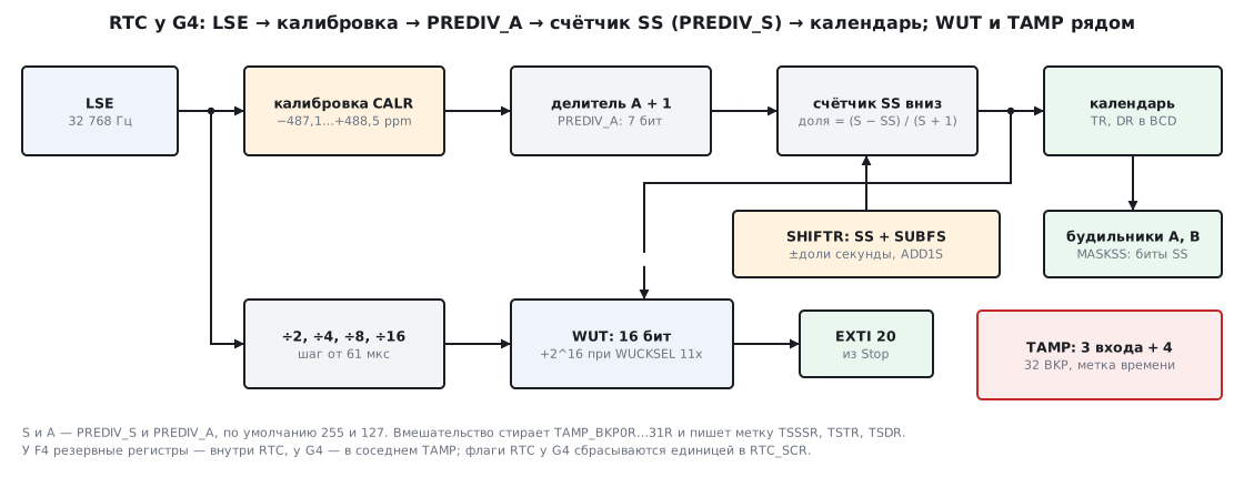
Enabling at register level. On the G4 the RTC has its own bus clock — the RTCAPBEN bit,
and the clock source is selected in RCC_BDCR once: RTCSEL can later be changed
only by a backup domain reset or after an LSE failure:
void rtc_lse_on(void)
{
    RCC->APB1ENR1 |= RCC_APB1ENR1_PWREN | RCC_APB1ENR1_RTCAPBEN;   /* у G4 у RTC свой такт шины */
    PWR->CR1 |= PWR_CR1_DBP;                /* доступ к резервному домену */
    RCC->BDCR |= RCC_BDCR_LSEON;
    while (!(RCC->BDCR & RCC_BDCR_LSERDY)) { }
    RCC->BDCR |= RCC_BDCR_RTCSEL_0 | RCC_BDCR_RTCEN;   /* 01 — LSE; сменить потом — только сбросом домена */
}
The write protection keys in RTC_WPR are the same as on the F4: 0xCA and 0x53. In the examples
below they are written by rtc_unlock, and rtc_lock restores protection by writing 0xFF.
12а.2 Two prescalers and subseconds
A second is made from 32 768 Hz by two prescalers in series (RM0440, 35.3.4):
ck_apre = 32 768 / (PREDIV_A + 1), 1 Hz = ck_apre / (PREDIV_S + 1).
The asynchronous PREDIV_A is 7 bits, the synchronous PREDIV_S is 15 bits; the total
division ratio is from 1 to 2²² = 4 194 304. The synchronous one is the SS counter itself
in the RTC_SSR register: it counts down from PREDIV_S to zero at the ck_apre clock.
Hence the fraction of a second:
fraction = (PREDIV_S − SS) / (PREDIV_S + 1).
With the default prescalers (127 and 255) SS = 191 is 0.25 s, SS = 127 is 0.5 s, SS = 0 is 0.99609 s. The step is 1 / (PREDIV_S + 1), and it can be made finer by moving the division into the synchronous prescaler:
PREDIV_A |
PREDIV_S |
ck_apre | Subsecond step | CALP |
|---|---|---|---|---|
| 127 | 255 | 256 Hz | 3906.25 µs | allowed |
| 31 | 1023 | 1024 Hz | 976.56 µs | allowed |
| 7 | 4095 | 4096 Hz | 244.14 µs | allowed |
| 3 | 8191 | 8192 Hz | 122.07 µs | allowed |
| 0 | 32767 | 32768 Hz | 30.52 µs | not allowed |
The price of a fine step is current: the faster ck_apre, the higher the
consumption of the clock may be, and RM0440 advises keeping PREDIV_A large (the manual
gives no current figures). The second limitation is calibration: with PREDIV_A less than 3
CALP has no effect (12а.3). So 3 and 8191 give the finest step, 122 µs,
with the full calibration range. Two more conditions from RM0440: an alarm on
seconds requires PREDIV_S of at least 3, and trimming to the 50 or 60 Hz mains
(REFCKON) requires the default prescalers.
The prescalers are written in configuration mode, and RM0440 requires PRER to be written in two
separate accesses (HAL for G4 writes it in one):
void rtc_prescalers(uint32_t a, uint32_t s)
{
    rtc_unlock();
    RTC->ICSR |= RTC_ICSR_INIT;             /* календарь стоит */
    while (!(RTC->ICSR & RTC_ICSR_INITF)) { }
    RTC->PRER = s;                          /* RM0440: две раздельные записи */
    RTC->PRER = s | (a << RTC_PRER_PREDIV_A_Pos);
    RTC->ICSR &= ~RTC_ICSR_INIT;            /* пошёл через 4 такта RTCCLK */
    rtc_lock();
}
INITF rises after about 2 RTCCLK cycles — 61.0 µs, and after INIT is cleared
the calendar starts after 4 cycles — 122.1 µs.
Shifting by a fraction of a second
If the clock has to be brought into line with exact time — from GPS, a time server, another
device — there is no need to stop the calendar. A write to RTC_SHIFTR
adds SUBFS to the SS counter, and since it counts down, the clock falls behind by
SUBFS / (PREDIV_S + 1) s. With the ADD1S bit a whole second is added to this,
and the clock moves forward by 1 − SUBFS / (PREDIV_S + 1) s:
| Needed | PREDIV_S |
SHIFTR |
Result |
|---|---|---|---|
| back by 0.1 s | 255 | 0x0000001A | −0.101562 s |
| back by 0.1 s | 8191 | 0x00000333 | −0.099976 s |
| forward by 0.25 s | 255 | 0x800000C0 | +0.250000 s |
| forward by 0.25 s | 8191 | 0x80001800 | +0.250000 s |
A model of the counter on the PC — SS goes down, the shift adds SUBFS to it — after
three seconds of running gives the same difference as the formula. The accuracy of the shift is
the subsecond step: with 255 a shift back by 0.1 s is not exact, the error is 1.56 ms.
int rtc_shift(uint32_t add1s, uint32_t subfs)
{
    if (RTC->SSR & 0x8000u)                 /* SS[15] = 1 — новый сдвиг переполнит SS */
        return -1;
    rtc_unlock();
    while (RTC->ICSR & RTC_ICSR_SHPF) { }
    RTC->SHIFTR = (add1s ? RTC_SHIFTR_ADD1S : 0u) | subfs;
    rtc_lock();
    return 0;
}
After a shift SS may be greater than PREDIV_S, and then, according to RM0440, the correct time
is one second less than in TR. The fraction formula then simply gives
a negative number — compute it as signed:
int32_t rtc_ms(uint32_t ss, uint32_t prediv_s)
{
    return ((int32_t)prediv_s - (int32_t)ss) * 1000 / ((int32_t)prediv_s + 1);
}
12а.3 Smooth calibration: ppm instead of a trimmer capacitor
A watch crystal rarely gives exactly 32 768 Hz. An error of +20 ppm is 1.728 s
a day and 51.8 s in 30 days, of −35 ppm it is 3.024 s a day and 90.7 s a month.
The RTC_CALR register corrects this without trimming the crystal: in a cycle of 2²⁰
pulses — 32 s — it removes CALM pulses (0…511), and the CALP bit
adds 512 (RM0440, 35.3.13):
FCAL = F × [1 + (CALP × 512 − CALM) / (2²⁰ + CALM − CALP × 512)].
The range is from −487.1 to +488.5 ppm, the step is 0.9537 ppm. Selection: CALM −
512 × CALP ≈ 2²⁰ × the error. For +20 ppm this is 20.97 — CALM = 21; for −35 ppm
it is −36.70 — set CALP and CALM = 512 − 37 = 475. A PC model tries
all 1024 combinations and chooses the best:
| Crystal | Cycle | CALR |
Residual | Drift per day |
|---|---|---|---|---|
| +20 ppm | 32 s | 0x0015 | −0.027 ppm | 0.002 s |
| +20 ppm | 16 s | 0x2014 | +0.926 ppm | 0.080 s |
| +20 ppm | 8 s | 0x4014 | +0.926 ppm | 0.080 s |
| −35 ppm | 32 s | 0x81DB | +0.286 ppm | 0.025 s |
| −35 ppm | 16 s | 0xA1DC | −0.668 ppm | 0.058 s |
| −35 ppm | 8 s | 0xC1DC | −0.668 ppm | 0.058 s |
A short cycle (CALW16, CALW8) is needed to check the result faster,
but it coarsens the step: the low bit of CALM sticks at zero with 16 s, the two
low bits with 8 s. The rate is checked on the CALIB output on RTC_OUT1 (PC13):
with the default prescalers this is 512 Hz with COSEL = 0 or 1 Hz with
COSEL = 1. If you measure exactly one cycle,
the measurement error is half a clock per window: 0.477 ppm over 32 s, 0.954 ppm over 16 s,
1.907 ppm over 8 s.
The removed pulses are spread over the cycle: according to RM0440, the CALM[0] bit removes
a pulse at cal_cnt = 0x80000, CALM[1] at 0x40000 and 0xC0000 and so
on up to CALM[8] — 256 pulses of the form 0xXX800. A PC model lays them out
by these rules: for any CALM and any cycle start, the lag behind
uniform is no more than 1.89 pulses. So the clock is calibrated over
short intervals too, not only once every 32 s. A simple count of pulses
per cycle differs from the RM formula by no more than 0.24 ppm — less than one step.
CALR can be changed on the fly, but only when RECALPF = 0: until the previous
value has been accepted, the register is locked. The new value takes effect within three
ck_apre cycles — 11.72 ms at 256 Hz:
void rtc_calibrate(uint32_t calr)
{
    rtc_unlock();
    while (RTC->ICSR & RTC_ICSR_RECALPF) { }    /* прошлая запись ещё не принята */
    RTC->CALR = calr;
    rtc_lock();
}
12а.4 The wakeup timer and an alarm with subseconds
The alarm from section 12.6 is tied to the calendar, and for "wake up in
N" there is a separate 16-bit timer WUT: it counts down from the value of
RTC_WUTR, every WUT + 1 cycles it raises WUTF and reloads itself.
The clock is chosen by WUCKSEL (RM0440, 35.3.7):
WUCKSEL |
Clock | Step | Period |
|---|---|---|---|
| 000 | RTCCLK / 16 | 488.28 µs | from 0.488 ms to 32 s |
| 001 | RTCCLK / 8 | 244.14 µs | from 0.244 ms to 16 s |
| 010 | RTCCLK / 4 | 122.07 µs | from 0.122 ms to 8 s |
| 011 | RTCCLK / 2 | 61.04 µs | from 0.122 ms to 4 s |
| 10x | ck_spre, 1 Hz | 1 s | from 1 to 65 536 s — 18.2 h |
| 11x | ck_spre plus 2¹⁶ | 1 s | from 65 537 to 131 072 s — 36.4 h |
With RTCCLK / 2 the value WUT = 0 is forbidden, so the minimum is two cycles. With 11x 2¹⁶ is added to the counter: the timer becomes 17-bit. The choice by period is the finest step into which the period fits:
| Period | WUCKSEL |
WUT |
Result |
|---|---|---|---|
| 1 ms | 011 | 15 (0x000F) | 0.977 ms, −2.344 % |
| 100 ms | 011 | 1637 (0x0665) | 99.976 ms, −0.024 % |
| 1 s | 011 | 16383 (0x3FFF) | exactly 1 s |
| 10 min | 100 | 599 (0x0257) | exactly 600 s |
| 24 h | 110 | 20863 (0x517F) | exactly 86 400 s |
A second can also be taken from ck_spre with WUT = 0 — the same clock that drives the calendar. A millisecond cannot be exact: a 32 768 Hz crystal has no whole number of cycles in 1 ms.
void rtc_wakeup(uint32_t wucksel, uint32_t wut)
{
    rtc_unlock();
    RTC->CR &= ~(RTC_CR_WUTE | RTC_CR_WUTIE);
    while (!(RTC->ICSR & RTC_ICSR_WUTWF)) { }   /* WUTR и WUCKSEL можно менять */
    RTC->WUTR = wut;
    RTC->CR = (RTC->CR & ~RTC_CR_WUCKSEL) | wucksel;
    RTC->SCR = RTC_SCR_CWUTF;
    RTC->CR |= RTC_CR_WUTIE | RTC_CR_WUTE;
    rtc_lock();
    EXTI->IMR1 |= EXTI_IMR1_IM20;           /* из Stop будит линия EXTI 20 */
    EXTI->RTSR1 |= EXTI_RTSR1_RT20;
    NVIC_EnableIRQ(RTC_WKUP_IRQn);
}

void RTC_WKUP_IRQHandler(void)
{
    if (RTC->SR & RTC_SR_WUTF) {
        RTC->SCR = RTC_SCR_CWUTF;           /* единица в SCR — без ключей и без INIT */
        wakeups++;
    }
    EXTI->PR1 = EXTI_PR1_PIF20;
}
The timer wakes from Stop through EXTI line 20 on the rising edge (RM0440,
6.3.10), the alarm through line 17. The first WUTF comes not after WUT + 1
cycles, but between WUT and WUT + 1 after WUTE: for 10 minutes between 599 and 600 s,
and with ck_spre and WUT = 0 at any moment of the first second.
Alarm with subseconds
Next to RTC_ALRMAR from section 12.6 the G4 has RTC_ALRMASSR: the SS
value and MASKSS — how many of its low bits to compare. If all fields of
ALRMAR are masked, the mask alone gives a periodic alarm.
A PC model with PREDIV_S = 255:
MASKSS |
Compared | Fires |
|---|---|---|
| 0 | nothing, fires on the change of second | once every 1 s |
| 1 | SS[0] | once every 7.812 ms |
| 6 | SS[5:0] | once every 0.25 s |
| 7 | SS[6:0] | once every 0.5 s |
| 8 | SS[7:0] | once every 1 s |
| 15 | all 15 bits | once every 1 s |
An alarm "every day at 07:15:00.500" is ALRMAR = 0x80071500 from
section 12.6 and ALRMASSR = 0x0F00007F: SS = 127 is the middle of the second.
Writing is as on the F4, after ALRAWF, only the flag is cleared by a one
in SCR:
void rtc_alarm_a_ss(uint32_t alrmar, uint32_t maskss, uint32_t ss)
{
    rtc_unlock();
    RTC->CR &= ~(RTC_CR_ALRAE | RTC_CR_ALRAIE);
    while (!(RTC->ICSR & RTC_ICSR_ALRAWF)) { }
    RTC->ALRMAR = alrmar;
    RTC->ALRMASSR = (maskss << RTC_ALRMASSR_MASKSS_Pos) | ss;
    RTC->SCR = RTC_SCR_CALRAF;
    RTC->CR |= RTC_CR_ALRAE | RTC_CR_ALRAIE;
    rtc_lock();
}
12а.5 Reading the calendar: shadow registers and BYPSHAD
RTC_SSR, RTC_TR and RTC_DR are by default read from shadow copies:
the calendar is copied there all the time and raises RSF. The rules of
RM0440 (35.3.9):
- the APB bus must be no slower than 7 × RTCCLK — 229 376 Hz with LSE;
otherwise the RM requires
BYPSHAD= 1; - reading
SSRorTRfreezes the higher copies untilDRis read — read in the orderSSR,TR,DR, and then the three values are consistent; - in Stop and Standby no copying takes place; after exit the copies are updated
not at once but within 4 RTCCLK cycles — 122.1 µs. So after wakeup
RSFis cleared and waited for again:
void rtc_resync(void)
{
    rtc_unlock();
    RTC->ICSR &= ~RTC_ICSR_RSF;
    rtc_lock();
    while (!(RTC->ICSR & RTC_ICSR_RSF)) { }
}
With BYPSHAD = 1 there is no need to wait for RSF — the values come straight from the counters,
but nobody promises consistency either: a clock tick may come between the reads.
A PC model sets the clock to 12:00:00 with SS = 0 — the last cycle of the second —
and lets it tick right after the first read:
| How it was read | Shown | Actually | Error |
|---|---|---|---|
TR, then SSR |
12:00:00.000 | 12:00:01.000 | −1 s |
SSR, then TR |
12:00:01.996 | 12:00:01.000 | +0.996 s |
SSR, TR, DR and SSR again |
12:00:01.000 | 12:00:01.000 | none |
The cure is the same as for the F1 counter in section 12.6: re-read the lowest register and repeat if it has changed. RM0440 advises exactly this — compare two reads of the lowest calendar register. In the rare case of a tick between the reads this is eight accesses instead of four:
void rtc_read(rtc_now_t *t)
{
    do {
        t->ss = RTC->SSR;
        t->tr = RTC->TR;
        t->dr = RTC->DR;
    } while (t->ss != RTC->SSR);
}
12а.6 TAMP: tamper, timestamp, backup registers
The G474 has 32 backup registers TAMP_BKP0R…BKP31R — from 0x4000 2500
to 0x4000 257C. Neither a system reset nor exit from Standby resets them,
and they are powered from VBAT. Writing requires DBP, like everything in the backup
domain (section 10.5):
void bkp_write(uint32_t i, uint32_t v)
{
    (&TAMP->BKP0R)[i] = v;                  /* нужен DBP; пока стоит флаг вмешательства — не запишется */
}
armclang turns it into a single write to address 0x4000 2500 + 4 × i:
bkp_write: MOVW  r2,#0x2500
           MOVT  r2,#0x4000
           STR   r1,[r2,r0,LSL #2]
           BX    lr
Tamper erases them. By default any TAMP event clears all
backup registers, and they are held at zero while at least one tamper flag
is set. Not erasing can be chosen per input: TAMPxNOER or TAMPxMSK
in TAMP_CR2 — in the header these bits are called TAMP1NOERASE and TAMP1MF.
The registers are also erased when Flash read protection is lowered from level 1 to 0.
There are seven tamper sources. Three external inputs — TAMP_IN1…TAMP_IN3;
four internal: LSE failure, HSE failure, calendar overflow (31 December
of year 99, 23:59:59 — after that the calendar stops) and ST factory read-out.
After a backup domain reset TAMP_CR1 = 0xFFFF 0000 — the bits
ITAMP3E…ITAMP6E are already set.
An external input works in two ways:
- on an edge (
TAMPFLT= 0) — the pull-up is off; RM0440 advises reading the pin level right after enabling: if the active level is already present, the event comes immediately; - on a level with a filter — the input is precharged before each sample
(1…8 RTCCLK cycles,
TAMPPRCH), sampled at a rate from 1 to 128 Hz (TAMPFREQ), the event comes after 2, 4 or 8 consecutive samples (TAMPFLT). The delay is from 2 samples at 128 Hz, 0.0156 s, to 8 samples at 1 Hz — 8 s.
The detector works even with VDD removed, so the input must be reliably
pulled to the inactive level — otherwise noise will erase the registers. Example:
when opened, the case lid shorts TAMP_IN1 (PC13) to ground, 4 samples at 16 Hz —
0.25 s:
void tamp_in1_setup(void)
{
    TAMP->FLTCR = (2u << TAMP_FLTCR_TAMPFLT_Pos) | (4u << TAMP_FLTCR_TAMPFREQ_Pos);
    TAMP->CR2 &= ~(TAMP_CR2_TAMP1NOERASE | TAMP_CR2_TAMP1MF | TAMP_CR2_TAMP1TRG);  /* низкий уровень — вскрытие */
    TAMP->IER |= TAMP_IER_TAMP1IE;
    TAMP->CR1 |= TAMP_CR1_TAMP1E;
    rtc_unlock();
    RTC->CR |= RTC_CR_TAMPTS;               /* метка времени на вмешательство, даже при TSE = 0 */
    rtc_lock();
    EXTI->IMR1 |= EXTI_IMR1_IM19;           /* вмешательство и метка — линия EXTI 19 */
    EXTI->RTSR1 |= EXTI_RTSR1_RT19;
    NVIC_EnableIRQ(RTC_TAMP_LSECSS_IRQn);
}
A timestamp is the calendar written into RTC_TSSSR, RTC_TSTR
and RTC_TSDR at the moment of an event. There are three events: an edge on RTC_TS (bit TSE),
switching to the battery (ITSE) and tamper (TAMPTS). TSF rises
after 2 ck_apre cycles — 7.81 ms at 256 Hz; a second event while
TSF is set raises TSOVF, and the registers keep the first. There is no year in the stamp:
RTC_TSDR has only the weekday, month and day. And most importantly — clearing TSF
clears the stamp, so read first, then clear:
void RTC_TAMP_LSECSS_IRQHandler(void)
{
    if (TAMP->SR & TAMP_SR_TAMP1F) {
        if (RTC->SR & RTC_SR_TSF) {         /* сначала прочитать: сброс TSF обнуляет метку */
            ts_ss = RTC->TSSSR;
            ts_time = RTC->TSTR;
            ts_date = RTC->TSDR;
            RTC->SCR = RTC_SCR_CTSF;
        }
        TAMP->SCR = TAMP_SCR_CTAMP1F;       /* пока флаг стоит, резервные регистры держатся в нуле */
        tampers++;
    }
    EXTI->PR1 = EXTI_PR1_PIF19;
}
PC13 carries RTC_OUT1, RTC_TS and TAMP_IN1 at once, and these functions
work in all sleep modes and from the battery.
12а.7 Pitfalls
The RTC registers do not respond. On the G4 the clock has its own bus clock:
RTCAPBEN in RCC_APB1ENR1 is not set.
The clock source will not change. RTCSEL is selected once; changing it is
possible only by a backup domain reset (BDRST), and that erases the clock too.
CALP has no effect. PREDIV_A is less than 3 — then RM0440 treats CALP
as zero. The finest step with full calibration is prescalers 3 and 8191.
The write to CALR was lost. RECALPF was set: the register is locked until
the previous value is accepted.
An odd CALM does not work. CALW16 (or CALW8) is on: the low bits
stick at zero, the step is 1.907 ppm (or 3.815 ppm).
The seconds alarm is silent. PREDIV_S is less than 3, and MSK1 = 0.
After wakeup the time is old. In Stop the shadow copies are not updated:
clear RSF and wait for it.
The time occasionally jumps by a second. BYPSHAD = 1, and SSR and TR were read
without a repeat — a tick fell between the reads.
The first wakeup is early. The first WUTF comes between WUT and WUT + 1
cycles; with ck_spre and WUT = 0 at any moment of the first second.
WUTR will not write. WUTE was not cleared or WUTWF was not waited for.
The shift did not work. SHPF was set (the previous shift is in progress), SS[15] = 1 or
REFCKON is on — the shift is incompatible with mains trimming.
The flag is cleared as on the F4. A zero in RTC_SR does nothing — on the G4 the flags
are cleared by a one in RTC_SCR.
A backup register will not write. No DBP — or a tamper flag is set:
until it is cleared, the registers are held at zero.
The backup registers erased themselves. A tamper input fired (it is floating, or edge mode was enabled while the active level was present), an internal source, or read protection was lowered from level 1 to 0.
The timestamp is empty. TSF was cleared before TSTR
and TSDR were read — clearing it zeroes them.
F4 backup register code does not build. On the G4 they are in TAMP, not
in RTC: TAMP->BKP0R.
12а.8 Summary
- Second = 32 768 / ((PREDIV_A + 1) × (PREDIV_S + 1)); fraction = (PREDIV_S − SS) / (PREDIV_S + 1); step from 3906.25 µs (127 and 255) to 30.52 µs (0 and 32767); with full calibration down to 122.07 µs (3 and 8191).
SHIFTRmoves the clock by a fraction of a second without stopping: back by SUBFS / (PREDIV_S + 1), withADD1Sforward by 1 − SUBFS / (PREDIV_S + 1).- Smooth calibration: from −487.1 to +488.5 ppm in steps of 0.9537 ppm over a 32 s cycle;
+20 ppm —
CALR= 0x0015, −35 ppm — 0x81DB, residual under 0.3 ppm against 1.728 and 3.024 s a day without calibration. - Wakeup timer: from 0.122 ms to 36.4 h; 10 min — ck_spre and WUT = 599,
a day —
WUCKSEL110 and WUT = 20863; wakes from Stop through EXTI 20. MASKSSadds subseconds to the alarm and gives periods shorter than a second: 0.25 s withMASKSS= 6 andPREDIV_S= 255.- The calendar is read in the order
SSR,TR,DR; after Stop wait forRSF; withBYPSHAD= 1 re-readSSR— otherwise an error of up to a second. - TAMP on the G474: 3 inputs, 4 internal sources, 32 backup registers
(16 on the G431, 20 inside the RTC on the F407); tamper erases them and writes
a timestamp without the year; RTC and TAMP flags are cleared by a one in
SCR.
Full sources
rtc12a.c — RTC and TAMP of the STM32G474 at register level.
/* 12а: RTC и TAMP у STM32G474 по регистрам — LSE, делители, гладкая калибровка, сдвиг на доли
 * секунды, таймер пробуждения, будильник с субсекундами, чтение календаря, резервные регистры
 * TAMP, вход вмешательства с меткой времени. Собирается armclang: -DSTM32G474xx (и -DSTM32G431xx —
 * у него резервных регистров 16). Числа — RM0440, главы 35 и 36; проверка — _verify/rtc12a_check.py. */
#include <stdint.h>
#include <stddef.h>

#define WUCKSEL_DIV2    3u                  /* 011: RTCCLK / 2, шаг 61 мкс */
#define WUCKSEL_1HZ     4u                  /* 10x: ck_spre, обычно 1 Гц */
#define WUCKSEL_1HZ_17  6u                  /* 11x: ck_spre, к WUT добавляется 2^16 */
#define CALR_FAST_20PPM 21u                 /* кварц спешит на 20 ppm: замаскировать 21 импульс из 2^20 */
#define CALR_SLOW_35PPM (RTC_CALR_CALP | 475u)  /* отстаёт на 35 ppm: +512 − 475 = +37 импульсов */

_Static_assert(RTC_BASE == 0x40002800u && TAMP_BASE == 0x40002400u, "RTC и TAMP — соседние блоки на APB1");
_Static_assert(offsetof(RTC_TypeDef, SSR) == 0x08u && offsetof(RTC_TypeDef, ICSR) == 0x0Cu
               && offsetof(RTC_TypeDef, PRER) == 0x10u && offsetof(RTC_TypeDef, WUTR) == 0x14u
               && offsetof(RTC_TypeDef, CR) == 0x18u && offsetof(RTC_TypeDef, WPR) == 0x24u
               && offsetof(RTC_TypeDef, CALR) == 0x28u && offsetof(RTC_TypeDef, SHIFTR) == 0x2Cu
               && offsetof(RTC_TypeDef, TSSSR) == 0x38u && offsetof(RTC_TypeDef, ALRMASSR) == 0x44u
               && offsetof(RTC_TypeDef, SR) == 0x50u && offsetof(RTC_TypeDef, SCR) == 0x5Cu,
               "смещения регистров RTC — по таблице 336 RM0440");
_Static_assert(offsetof(TAMP_TypeDef, BKP0R) == 0x100u && RTC_TAMP_NB == 3u && RTC_TAMP_INT_NB == 4u,
               "резервные регистры с 0x100; три внешних входа и четыре внутренних источника");
#if defined(STM32G474xx)
_Static_assert(RTC_BACKUP_NB == 32u && offsetof(TAMP_TypeDef, BKP31R) == 0x17Cu, "у G474 — 32 регистра");
#elif defined(STM32G431xx)
_Static_assert(RTC_BACKUP_NB == 16u && offsetof(TAMP_TypeDef, BKP15R) == 0x13Cu, "у G431 — 16 регистров");
#endif
_Static_assert(RTC_PRER_PREDIV_A_Pos == 16u && RTC_PRER_PREDIV_A_Msk == (0x7Fu << 16)
               && RTC_PRER_PREDIV_S_Msk == 0x7FFFu, "PREDIV_A — 7 бит с 16-го, PREDIV_S — 15 бит");
_Static_assert(RTC_SSR_SS_Msk == 0xFFFFu && RTC_ALRMASSR_SS_Msk == 0x7FFFu && RTC_ALRMASSR_MASKSS_Pos == 24u,
               "SS — 16 бит (15-й — переполнение после сдвига), в будильнике — 15, MASKSS с 24-го бита");
_Static_assert(RTC_CALR_CALP == (1u << 15) && RTC_CALR_CALW8 == (1u << 14) && RTC_CALR_CALW16 == (1u << 13)
               && RTC_CALR_CALM_Msk == 0x1FFu, "CALP, CALW8, CALW16 — биты 15, 14, 13; CALM — 9 бит");
_Static_assert(CALR_FAST_20PPM == 0x0015u && CALR_SLOW_35PPM == 0x81DBu, "CALR для +20 и −35 ppm");
_Static_assert(RTC_SHIFTR_ADD1S == (1u << 31) && RTC_SHIFTR_SUBFS_Msk == 0x7FFFu, "ADD1S — бит 31, SUBFS — 15 бит");
_Static_assert(RTC_CR_WUCKSEL_Msk == 7u && RTC_WUTR_WUT_Msk == 0xFFFFu && RTC_CR_WUTE == (1u << 10)
               && RTC_CR_WUTIE == (1u << 14) && RTC_CR_BYPSHAD == (1u << 5),
               "WUCKSEL — 3 бита, WUT — 16, WUTE — бит 10, WUTIE — 14, BYPSHAD — 5");
_Static_assert(RTC_ICSR_WUTWF == (1u << 2) && RTC_ICSR_SHPF == (1u << 3) && RTC_ICSR_RSF == (1u << 5)
               && RTC_ICSR_INITF == (1u << 6) && RTC_ICSR_INIT == (1u << 7) && RTC_ICSR_RECALPF == (1u << 16),
               "флаги ICSR");
_Static_assert(RTC_SR_WUTF == (1u << 2) && RTC_SCR_CWUTF == RTC_SR_WUTF && RTC_SCR_CTSF == RTC_SR_TSF,
               "флаг в SR и бит его сброса в SCR — на одном месте");
_Static_assert(TAMP_FLTCR_TAMPFREQ_Pos == 0u && TAMP_FLTCR_TAMPFLT_Pos == 3u && TAMP_FLTCR_TAMPPRCH_Pos == 5u
               && TAMP_FLTCR_TAMPPUDIS == (1u << 7), "поля TAMP_FLTCR");
_Static_assert(TAMP_CR2_TAMP1NOERASE == 1u && TAMP_CR2_TAMP1MF == (1u << 16) && TAMP_CR2_TAMP1TRG == (1u << 24),
               "TAMP1NOER и TAMP1MSK из RM в заголовке называются TAMP1NOERASE и TAMP1MF");
_Static_assert(RCC_BDCR_RTCSEL_0 == (1u << 8) && RCC_BDCR_RTCEN == (1u << 15) && RCC_APB1ENR1_RTCAPBEN == (1u << 10)
               && PWR_CR1_DBP == (1u << 8), "RTCSEL = 01 — LSE; RTCEN; такт шины RTC; DBP");
_Static_assert(EXTI_IMR1_IM20 == (1u << 20) && RTC_WKUP_IRQn == 3 && RTC_TAMP_LSECSS_IRQn == 2,
               "таймер пробуждения — линия EXTI 20");

volatile uint32_t wakeups, tampers;
volatile uint32_t ts_time, ts_date, ts_ss;

static void rtc_unlock(void)
{
    RTC->WPR = 0xCAu;                       /* ключи те же, что у F4 */
    RTC->WPR = 0x53u;
}

static void rtc_lock(void)
{
    RTC->WPR = 0xFFu;
}

void rtc_lse_on(void)
{
    RCC->APB1ENR1 |= RCC_APB1ENR1_PWREN | RCC_APB1ENR1_RTCAPBEN;   /* у G4 у RTC свой такт шины */
    PWR->CR1 |= PWR_CR1_DBP;                /* доступ к резервному домену */
    RCC->BDCR |= RCC_BDCR_LSEON;
    while (!(RCC->BDCR & RCC_BDCR_LSERDY)) { }
    RCC->BDCR |= RCC_BDCR_RTCSEL_0 | RCC_BDCR_RTCEN;   /* 01 — LSE; сменить потом — только сбросом домена */
}

/* 1 Гц = 32768 / ((a + 1) × (s + 1)); шаг долей секунды — 1 / (s + 1) */
void rtc_prescalers(uint32_t a, uint32_t s)
{
    rtc_unlock();
    RTC->ICSR |= RTC_ICSR_INIT;             /* календарь стоит */
    while (!(RTC->ICSR & RTC_ICSR_INITF)) { }
    RTC->PRER = s;                          /* RM0440: две раздельные записи */
    RTC->PRER = s | (a << RTC_PRER_PREDIV_A_Pos);
    RTC->ICSR &= ~RTC_ICSR_INIT;            /* пошёл через 4 такта RTCCLK */
    rtc_lock();
}

void rtc_calibrate(uint32_t calr)
{
    rtc_unlock();
    while (RTC->ICSR & RTC_ICSR_RECALPF) { }    /* прошлая запись ещё не принята */
    RTC->CALR = calr;
    rtc_lock();
}

/* назад на subfs / (PREDIV_S + 1) с; с add1s — вперёд на 1 − subfs / (PREDIV_S + 1) */
int rtc_shift(uint32_t add1s, uint32_t subfs)
{
    if (RTC->SSR & 0x8000u)                 /* SS[15] = 1 — новый сдвиг переполнит SS */
        return -1;
    rtc_unlock();
    while (RTC->ICSR & RTC_ICSR_SHPF) { }
    RTC->SHIFTR = (add1s ? RTC_SHIFTR_ADD1S : 0u) | subfs;
    rtc_lock();
    return 0;
}

void rtc_wakeup(uint32_t wucksel, uint32_t wut)
{
    rtc_unlock();
    RTC->CR &= ~(RTC_CR_WUTE | RTC_CR_WUTIE);
    while (!(RTC->ICSR & RTC_ICSR_WUTWF)) { }   /* WUTR и WUCKSEL можно менять */
    RTC->WUTR = wut;
    RTC->CR = (RTC->CR & ~RTC_CR_WUCKSEL) | wucksel;
    RTC->SCR = RTC_SCR_CWUTF;
    RTC->CR |= RTC_CR_WUTIE | RTC_CR_WUTE;
    rtc_lock();
    EXTI->IMR1 |= EXTI_IMR1_IM20;           /* из Stop будит линия EXTI 20 */
    EXTI->RTSR1 |= EXTI_RTSR1_RT20;
    NVIC_EnableIRQ(RTC_WKUP_IRQn);
}

void RTC_WKUP_IRQHandler(void)
{
    if (RTC->SR & RTC_SR_WUTF) {
        RTC->SCR = RTC_SCR_CWUTF;           /* единица в SCR — без ключей и без INIT */
        wakeups++;
    }
    EXTI->PR1 = EXTI_PR1_PIF20;
}

/* будильник A: календарь как в разделе 12 плюс доли секунды — сравниваются SS[maskss−1:0] */
void rtc_alarm_a_ss(uint32_t alrmar, uint32_t maskss, uint32_t ss)
{
    rtc_unlock();
    RTC->CR &= ~(RTC_CR_ALRAE | RTC_CR_ALRAIE);
    while (!(RTC->ICSR & RTC_ICSR_ALRAWF)) { }
    RTC->ALRMAR = alrmar;
    RTC->ALRMASSR = (maskss << RTC_ALRMASSR_MASKSS_Pos) | ss;
    RTC->SCR = RTC_SCR_CALRAF;
    RTC->CR |= RTC_CR_ALRAE | RTC_CR_ALRAIE;
    rtc_lock();
}

typedef struct {
    uint32_t ss, tr, dr;
} rtc_now_t;

/* BYPSHAD = 1: SSR прочитан дважды одинаковым — между чтениями календарь не менялся */
void rtc_read(rtc_now_t *t)
{
    do {
        t->ss = RTC->SSR;
        t->tr = RTC->TR;
        t->dr = RTC->DR;
    } while (t->ss != RTC->SSR);
}

/* BYPSHAD = 0, после выхода из Stop: теневые регистры ещё старые */
void rtc_resync(void)
{
    rtc_unlock();
    RTC->ICSR &= ~RTC_ICSR_RSF;
    rtc_lock();
    while (!(RTC->ICSR & RTC_ICSR_RSF)) { }
}

/* доля секунды в миллисекундах; после сдвига SS бывает больше PREDIV_S — доля отрицательная */
int32_t rtc_ms(uint32_t ss, uint32_t prediv_s)
{
    return ((int32_t)prediv_s - (int32_t)ss) * 1000 / ((int32_t)prediv_s + 1);
}

void bkp_write(uint32_t i, uint32_t v)
{
    (&TAMP->BKP0R)[i] = v;                  /* нужен DBP; пока стоит флаг вмешательства — не запишется */
}

uint32_t bkp_read(uint32_t i)
{
    return (&TAMP->BKP0R)[i];
}

/* TAMP_IN1 (PC13): крышка замыкает вход на землю; 4 выборки подряд при 16 Гц — 0,25 с;
 * резервные регистры стираются, метка времени пишется */
void tamp_in1_setup(void)
{
    TAMP->FLTCR = (2u << TAMP_FLTCR_TAMPFLT_Pos) | (4u << TAMP_FLTCR_TAMPFREQ_Pos);
    TAMP->CR2 &= ~(TAMP_CR2_TAMP1NOERASE | TAMP_CR2_TAMP1MF | TAMP_CR2_TAMP1TRG);  /* низкий уровень — вскрытие */
    TAMP->IER |= TAMP_IER_TAMP1IE;
    TAMP->CR1 |= TAMP_CR1_TAMP1E;
    rtc_unlock();
    RTC->CR |= RTC_CR_TAMPTS;               /* метка времени на вмешательство, даже при TSE = 0 */
    rtc_lock();
    EXTI->IMR1 |= EXTI_IMR1_IM19;           /* вмешательство и метка — линия EXTI 19 */
    EXTI->RTSR1 |= EXTI_RTSR1_RT19;
    NVIC_EnableIRQ(RTC_TAMP_LSECSS_IRQn);
}

void RTC_TAMP_LSECSS_IRQHandler(void)
{
    if (TAMP->SR & TAMP_SR_TAMP1F) {
        if (RTC->SR & RTC_SR_TSF) {         /* сначала прочитать: сброс TSF обнуляет метку */
            ts_ss = RTC->TSSSR;
            ts_time = RTC->TSTR;
            ts_date = RTC->TSDR;
            RTC->SCR = RTC_SCR_CTSF;
        }
        TAMP->SCR = TAMP_SCR_CTAMP1F;       /* пока флаг стоит, резервные регистры держатся в нуле */
        tampers++;
    }
    EXTI->PR1 = EXTI_PR1_PIF19;
}
Next: section 12б "Firmware self-test: RAM, Flash, clocks and the core during operation" — a RAM march, image CRC against a reference, checking the frequency, the core registers and the stack.