 Embedded HandbookApps
51. Semiconductors: diodes, Zener diodes, bipolar transistors
A resistor does what Ohm's law tells it. Semiconductors behave differently — and that is exactly why rectifiers, regulators and switches are made from them. This section is about three parts that no board with a microcontroller can do without: the diode, which passes current in one direction; the Zener diode, which holds a voltage; the transistor, which lets a pin with its eight milliamps control a relay, a lamp or a motor.
All numbers are based on the datasheet parameters of specific common parts: a 1 A rectifier diode, a 5.6 V Zener diode and a 500 mA transistor.
Terms used in the documentation
Term Meaning p-n junction boundary between p-type and n-type semiconductor forward / reverse bias voltage applied in the conducting / blocking direction forward voltage drop (Vf) voltage across a conducting diode reverse breakdown sudden conduction at a high reverse voltage peak repetitive reverse voltage (VRRM) maximum allowed reverse voltage average rectified current maximum average forward current Schottky diode diode with a low forward drop flyback / freewheeling diode diode that absorbs the inductive kick of a coil Zener diode, Zener voltage (Vz) diode that holds a voltage in breakdown, and that voltage bipolar junction transistor (BJT) current-controlled transistor base, collector, emitter the three terminals of a BJT DC current gain (hFE, β) ratio of collector current to base current saturation, VCE(sat) fully-on state, and the voltage left across the transistor forced beta collector-to-base current ratio chosen by the designer for a switch cutoff / active / saturation region off / amplifying / fully-on mode
51.1 The diode: a valve with a toll
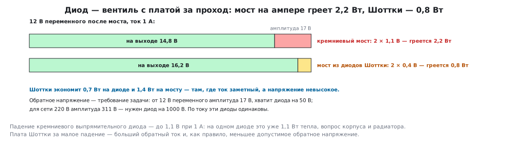
A diode passes current from anode to cathode and does not pass it back. But "passes" is not free: voltage drops across a conducting diode; for a silicon rectifier diode it is up to 1.1 V at 1 A. That means 1.1 W of heat in one diode at a current of one ampere — already a question of package and heatsink, not a trifle.
Three parameters for choosing a rectifier diode:
| Parameter | What it means | For a 1 A diode |
|---|---|---|
| average forward current | how much can flow continuously | 1 A |
| forward drop at this current | how much is lost as heat | up to 1.1 V |
| allowed reverse voltage | what the diode withstands when off | 50 … 1000 V |
The reverse voltage figure is not "the more, the better" but a requirement of the task: in a bridge from 12 V AC the amplitude is 17 V, and a 50 V diode is enough with margin; for 220 V mains the amplitude is 311 V, and you need a 1000 V diode. In current these diodes are the same.
A bridge means two diodes in the path. Rectifying 12 V AC, you get not 17 V but 17 − 2 × 1.1 = 14.8 V, and the bridge dissipates 2.2 W at 1 A.
The Schottky diode is the same valve with a drop of about 0.4 V instead of 1.1: at one ampere it saves 0.7 W, and in a bridge 1.4 W. The price is a higher reverse current and, as a rule, a lower allowed reverse voltage. Where the current is significant and the voltage is low — Schottky; in mains rectifiers — an ordinary silicon one.
51.2 The flyback diode: a mandatory part on any coil
A relay, a solenoid, a motor — these are inductances. An inductance does not let the current change instantly: when the switch opens, it raises the voltage as high as needed for the current to keep flowing.
A 12 V, 30 mA relay coil with an inductance of about 100 mH stores
45 µJ. Not much — but if the switch cuts the current within a microsecond, the voltage
U = L · di/dt rushes towards thousands of volts (in reality breakdown will limit it,
but not below hundreds). A microcontroller pin or a transistor will not
survive that.
The flyback diode is placed in parallel with the coil, cathode to plus. In normal
operation it is off; when the switch opens, the coil current closes through it, and
the voltage on the switch does not exceed the supply plus the diode drop —
13.1 V. The current decays through the diode and the resistance of the coil itself
(12 V / 30 mA = 400 Ω) in about 0.6 ms: t = (L/R) · ln(1 + I·R/Ud) =
0.25 ms · ln(1 + 12 / 1.1) ≈ 0.62 ms. The relay releases more slowly, the contacts
separate more slowly and burn more. If this matters, a Zener diode is placed in series
with the diode: the voltage on the switch rises to the supply plus
the Zener voltage, but the current decays several times faster.
⚠️ The diode is always needed, even if "the relay is small" and "the switch is powerful". The symptom of its absence: the device works for weeks, and then inexplicably resets, or the transistor burns out.
51.3 The Zener diode
A Zener diode is a diode that is connected in reverse and operated in breakdown: the voltage across it hardly depends on the current. A 5.6 V Zener diode rated at 500 mW withstands up to 89 mA.
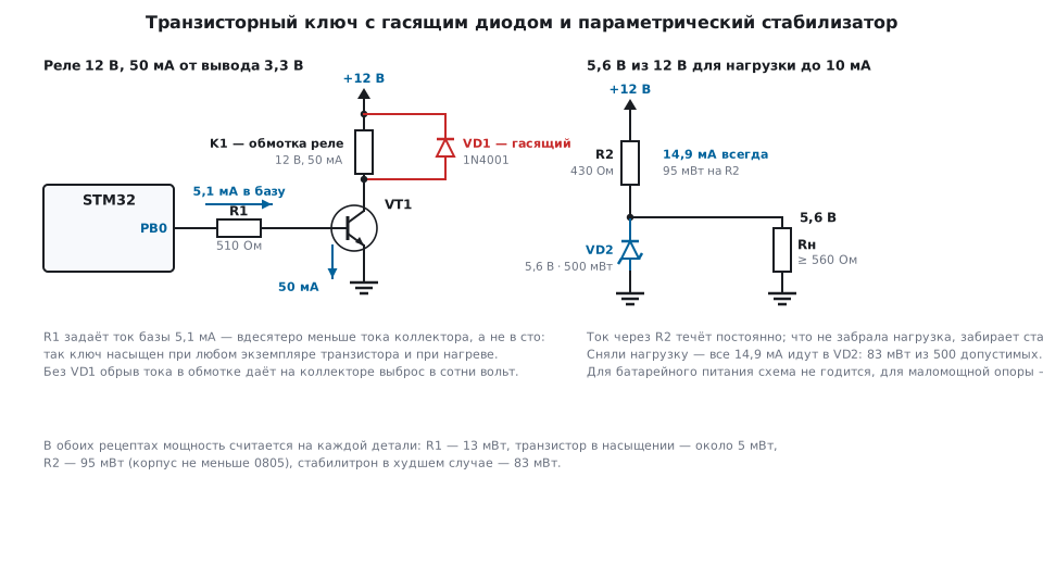
A shunt regulator is a series resistor and a Zener diode. The task: 5.6 V for a load of up to 10 mA from 12 V.
- The current through the resistor must cover the load and leave the Zener diode
a minimum to hold the voltage — take 5 mA:
R = (12 − 5.6) / 15 mA = 427 Ω; from the series, 430 Ω, current 14.9 mA. - The worst case for the Zener diode is when the load is disconnected: all 14.9 mA go into it, that is 83 mW out of the allowed 500. There is margin. But "12 V" from a battery or an unregulated supply goes up to 14.4 V: then the current is 20.5 mA, the Zener diode dissipates 115 mW, and the resistor 180 mW — you need a 1206 package.
- The resistor dissipates 95 mW — a package no smaller than 0805.
The properties that decide where the circuit is appropriate: the 14.9 mA current flows all the time, regardless of the load; the useful load gets only two thirds. For a comparator reference voltage or input protection — yes; for powering anything from a battery — no, you need a regulator there (section 55).
The second use is as a clamp for transients, but with low-voltage Zener diodes there is a caveat: their knee is soft. For a common 3.3 V Zener diode in a SOT-23 package, the datasheet gives a voltage at 5 mA from 3.14 to 3.47 V, and a differential resistance of up to 95 Ω at 5 mA and up to 600 Ω at 1 mA; for a 12 V Zener diode it is 25 and 150 Ω. Current already flows below the rated voltage — it loads the signal and distorts ADC readings — and every 10 mA of transient above 5 mA adds up to 0.95 V to the voltage, so the pin gets more than its 3.6 V. An input is better protected by a series resistor together with the pin's built-in diodes (62.3), and an external clamp is chosen for a voltage above the supply (62.9).
51.4 The transistor: control a large current with a small one
A bipolar transistor has three terminals: base, collector, emitter. A small base current opens a large collector current; the ratio is the current gain hFE. For a common 500 mA transistor it is from 100 to 600 at 100 mA and falls to 40 at the maximum current.
Two modes in which it is used:
- Switch — the transistor is either off or fully on (saturated). This is how relays, lamps and motors are controlled. Little heating, a simple mode, the current gain hardly matters.
- Amplifier — the operating point is in the middle, the output follows the input with gain. It always heats up and needs a bias calculation; in a digital circuit it is almost never found — that work is done by an operational amplifier (section 56).
51.5 🔧 A transistor switch
The task: a 12 V, 50 mA relay from a 3.3 V pin.
Base current. Per the datasheet, with hFE ≥ 100, 0.5 mA would be enough. But then the transistor will be on the edge — working as an amplifier, not a switch, and with another part or when heated it will stop turning fully on. In switch mode the base current is set by a forced gain of 10…20:
Iб = Iк / 10 = 50 мА / 10 = 5 мА
Rб = (3,3 В − 0,7 В) / 5 мА = 520 Ом  →  510 Ом, ток базы 5,1 мА
The 0.7 V subtracted is the drop across the base-emitter junction: it behaves like a diode. Without a base resistor this junction is almost a short circuit, and the current is limited only by the pin.
Checking the pin. 5.1 mA is within a comfortable 8 mA. But for a load of 100 mA the base would need 10 mA — the pin can deliver that only at its limit, and here you already need a field-effect transistor (section 52) or a compound circuit.
Losses. The saturation voltage grows with current. At 50 mA and a base current of 5 mA it is about 0.1 V (the model of section 170 gives 0.064 V): a few milliwatts, and less than one percent of the voltage fails to reach a 12 V load. At the maximum 500 mA and a base current of 50 mA the datasheet gives up to 0.7 V — 350 mW. At hundreds of milliamps a bipolar switch already heats up noticeably — this is the main reason why field-effect transistors are used for such currents.
Flyback diode — in parallel with the coil, as in section 51.2. Without it the very first turn-off of the relay will kill the transistor.
51.6 For comparison: the same transistor as an amplifier
To see how a switch differs from an amplifier, look at the same transistor with a 1 kΩ collector resistor from 12 V and the operating point in the middle: 6 mA through the collector, 6 V across the transistor. The voltage gain comes out at about 230 — impressive. But:
- 36 mW are dissipated constantly, just to hold the operating point — more than in a switch at ten times the current;
- the gain depends on current, temperature and the individual part;
- you need a bias circuit that stabilizes the operating point.
That is why, in circuits around a microcontroller, a discrete transistor appears almost exclusively as a switch, and amplification is left to operational amplifiers, which have all of this already solved inside.
51.7 Pitfalls
The relay does not switch on, or switches on "half-way". The base current was calculated from the datasheet hFE, not from the forced gain. Recalculate for Ic/10.
The transistor burned out when the relay was switched off. There is no flyback diode.
The microcontroller resets when the relay clicks. The same thing: the coil transient goes out along the supply and ground.
The transistor is hot. It is not saturated (base current too low) — or it is saturated, but the current is too large for a bipolar part: at hundreds of milliamps saturation reaches 0.7 V. Use a field-effect transistor.
The Zener diode heats up and "drifts". The load was disconnected and all the current went into the Zener diode; or the resistor was calculated without considering this case.
The voltage after the Zener diode is below the rated value. The current through it is less than the minimum — the load took it all. Reduce the resistor.
The rectifier gives less than expected. Two drops in the bridge, not one: minus 2.2 V.
The Schottky diode "leaks". Its reverse current is noticeably larger than that of a silicon diode, and it grows with temperature; in high-impedance circuits this shows.
There is no base resistor "because the pin is low-current". The pin is low-current until it is shorted into a junction with a drop of 0.7 V.
51.8 Summary
- A diode passes current in one direction, losing up to 1.1 V across itself: at 1 A that is 1.1 W, in a bridge twice as much; a Schottky diode saves 0.7 V.
- The reverse voltage of a diode is chosen by the task: 50 V for 12 V AC, 1000 V for mains.
- Every coil gets a flyback diode; otherwise there is a transient of hundreds of volts.
- A Zener diode holds a voltage at the cost of a constant current through the series resistor; calculate the worst case — no load.
- Bipolar switch: base current by a forced gain of 10…20, the base resistor is mandatory; losses are saturation voltage × current: about 0.1 V at 50 mA, up to 0.7 V at 500 mA.
- A 3.3 V Zener diode is a poor input clamp: the knee is soft, and current flows below the rated voltage.
- A microcontroller pin comfortably supplies up to 8 mA into a base — that is up to 50…80 mA in the load; beyond that, a field-effect transistor.
- An amplifier on a discrete transistor heats up and drifts; that work is given to operational amplifiers.
Next: section 52 "Switching loads: switches, relays, MOSFETs, drivers" — how to switch amperes rather than milliamps.