 Embedded HandbookApps
52. Switching loads: switches, relays, MOSFETs, drivers
A microcontroller pin delivers eight milliamps. A motor, a heater, an LED strip, a pump need amps. Between them sits a switch — and which switch you pick decides whether the device runs for years or burns out on the third power-up.
This section is about the choice: a bipolar transistor, a MOSFET, a relay or a ready-made module; why the gate of a MOSFET is a capacitor and why that makes a driver necessary; how much heat each option produces.
Terms used in the documentation
Term Meaning MOSFET, power MOSFET field-effect transistor with an insulated gate gate, drain, source the three terminals of a MOSFET gate threshold voltage (Vgs(th)) the gate voltage at which the channel starts to conduct logic level MOSFET a MOSFET specified for logic-level gate drive on-resistance (Rds(on)) resistance of the fully open channel gate charge (Qg), input capacitance (Ciss) charge needed to switch the gate, input capacitance gate driver a chip that charges and discharges the gate conduction / switching losses losses while on / losses during transitions low-side / high-side switch switch between load and ground / between supply and load bootstrap voltage boost for driving the high-side switch body diode the diode built into a MOSFET solid-state relay (SSR) a relay with no moving parts contact rating, cycles contact limits, mechanical lifetime inrush current current surge at switch-on
52.1 Three ways and their cost
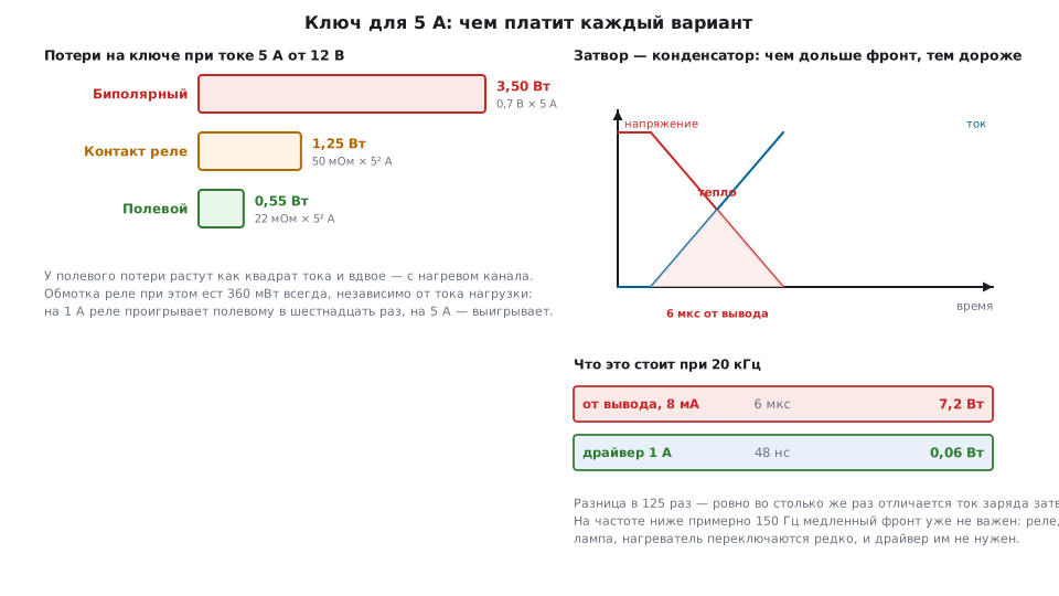
A 5 A load from 12 V is an everyday task (a motor, a strip, a heating element). Here is what each option loses:
| Switch | Losses | From |
|---|---|---|
| bipolar transistor | 3.50 W | 0.7 V × 5 A |
| relay contact | 1.25 W | 50 mΩ × 5² A |
| MOSFET | 0.55 W | 22 mΩ × 5² A |
The bipolar transistor loses by a factor of 6.4: its voltage drop barely depends on current, and at amps that is watts straight away. The MOSFET drops only 110 mV.
But the MOSFET's losses grow as the square of the current: 10 A already gives 2.2 W, four times as much. On top of that, the channel resistance grows with temperature — by 100 °C roughly twice, and 0.55 W turns into 1.1 W. Both effects must go into the heatsink calculation.
The relay stands apart: the contact loses little, but the coil eats 360 mW all the time, regardless of the load current. At a 1 A load the MOSFET loses 22 mW — the relay coil alone eats sixteen times more; at 5 A the relay loses 1.25 + 0.36 = 1.61 W against 0.55 W — almost three times the MOSFET. The relay wins only against the bipolar switch (3.5 W) — and where isolation is needed (52.6).
52.2 The gate is a capacitor
A MOSFET is controlled by voltage, not current: the gate draws no steady current. But the gate is a capacitor, and every switching event means charging and discharging it. The gate charge of a common transistor is 48 nC, which at 5 V corresponds to a capacitance of 9600 pF.
Hence the key number: how long the switching takes.
| Current source | Switching time |
|---|---|
| microcontroller pin, 8 mA | 6 µs |
| 0.5 A driver | 96 ns |
| 1 A driver | 48 ns |
A difference of 125 times. A driver is needed not because it is "more powerful", but because it delivers a large current for a short time.
The average current is tiny: with 20 kHz PWM the gate takes 0.96 mA, and the drive power is 4.8 mW. All the difficulty is in the peak, not the average.
52.3 Why a slow edge kills the transistor
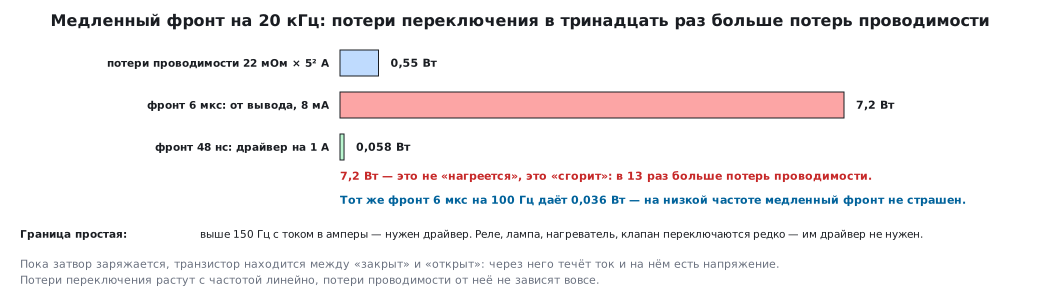
While the gate is charging, the transistor sits between "off" and "on": current flows through it and there is voltage across it at the same time. That is heat, and it is released on every transition.
At 12 V, 5 A and 20 kHz PWM:
| Drive | Edge | Switching losses |
|---|---|---|
| from a pin, 8 mA | 6 µs | 7.2 W |
| 1 A driver | 48 ns | 0.06 W |
7.2 W is not "it will get warm", it is "it will burn": thirteen times more than the conduction losses. A transistor that calmly carries 5 A continuously will be destroyed within seconds if you try to switch the same 5 A directly from a pin.
⚠️ Rule. A slow edge is acceptable only at low frequency. With the same 6 µs at 100 Hz the switching losses are 0.036 W, and when switching once a second they are negligible. The boundary is roughly this: above 150 Hz with currents of amps — you need a driver. A relay, a lamp, a heater, a valve switch rarely — they need no driver.
52.4 Gate circuitry
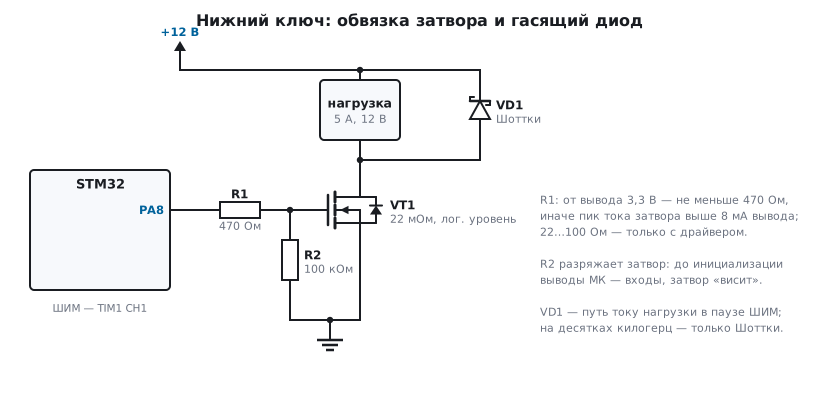
The gate resistor limits the current surge and damps ringing on the edge:
| Value | Peak current from 3.3 V |
|---|---|
| 22 Ω | 150 mA |
| 100 Ω | 33 mA |
| 470 Ω | 7 mA |
A microcontroller pin delivers 8 mA — so driving directly you can use only 470 Ω or more, and then the gate time constant is 4.5 µs. Small values (22…100 Ω) make sense only with a driver.
A gate-to-source pull-down is mandatory. Before initialization the microcontroller pins are inputs, the gate "floats" and can pick up charge from interference: the transistor will partly open at the worst possible moment. A 100 kΩ resistor wastes 33 µA in the on state and discharges the gate in 960 µs — that is enough.
Threshold. The threshold voltage Vgs(th) in the transistor datasheet does not mean
"turns on", it means "barely starts to conduct": it is specified at a drain current of
fractions of a milliamp. For amps of load you look at another line — the channel
resistance at a given gate voltage. The transistor in the example has a threshold
of up to 2.0 V, and its 22 mΩ is promised at 5 V; at 3.3 V the channel is noticeably worse, and
by how much the datasheet often does not say. For driving directly from a 3.3 V pin
you take a transistor whose channel resistance is specified at 2.5 or
2.7 V. An ordinary MOSFET is specified at 10 V on the
gate: from 3.3 V it is almost off, the channel is several or tens of times worse,
and instead of 0.55 W you get 2.75 or 11 W. This is the most common and the most
expensive beginner's mistake.
52.5 Low-side and high-side switches
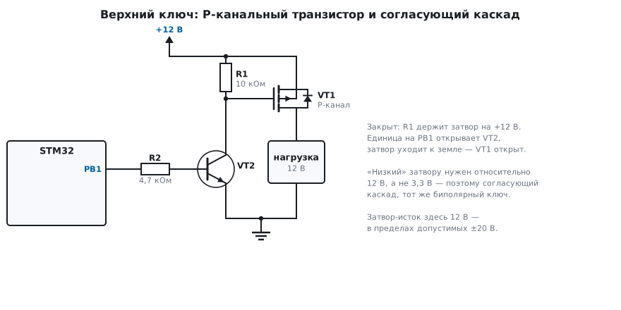
A low-side switch is a transistor between the load and ground. The source is at ground, so the gate-source voltage equals the pin voltage: simple, and it works. The downside is that the load is always under voltage; its "minus" side is what gets switched.
A high-side switch is a transistor between the supply and the load. The same N-channel transistor will not turn on here: its source "hangs" on the load and rises almost to the supply, so relative to the source the gate sees zero or a negative voltage. To turn it on, the gate needs 17 V — above the load supply.
There are three solutions:
- A P-channel transistor — turns on with a low level on the gate, but "low" for it means relative to 12 V, not 3.3; you need a level-shifting stage (the same bipolar switch).
- A bootstrap driver — a capacitor is recharged from the driver's supply while the low-side switch is on, and lifts the high-side gate above the supply; most half-bridge drivers work this way. Hence a limitation: the duty cycle cannot stay at 100 % for long — without recharging, the capacitor discharges through the driver current and leakage, and the high-side switch turns off by itself. For a load that is switched on and held, you take a driver with a built-in charge pump, a ready-made high-side switch chip or a P-channel transistor.
- A ready-made high-side switch chip — with built-in protection against overcurrent and overtemperature, driven directly by a logic level.
For bridge circuits (a motor in both directions, the converters from section 46.3) a high-side switch is unavoidable, and a half-bridge driver is used there.
52.6 Relays: when they are appropriate
| Property | Value | What follows |
|---|---|---|
| coil | 360 mW continuously | not for battery power |
| contact | tens of mΩ | loses 1.25 W at 5 A |
| operate time | ~10 ms | a hundred thousand times slower than a MOSFET |
| lifetime | ~100000 cycles | once a minute — 69 days; once a day — 273 years |
| isolation | galvanic | the main advantage |
A relay is chosen for isolation and the versatility of its contact: it switches DC, AC, signals and power equally well, does not depend on polarity and has no leakage when open. The price is slowness, wear and the click.
A relay must not go where switching is frequent: its lifetime will run out. The calculation is simple — 100000 cycles divided by the switching rate.
Saving on holding: a relay pulls in at full current but holds at a third — reducing the current after pull-in (PWM on the coil) saves up to 240 mW out of 360. The same is done with a "capacitor in parallel with a resistor" circuit: at the start the capacitor passes the full current, after that the resistor limits it.
A flyback diode is mandatory — section 51.2.
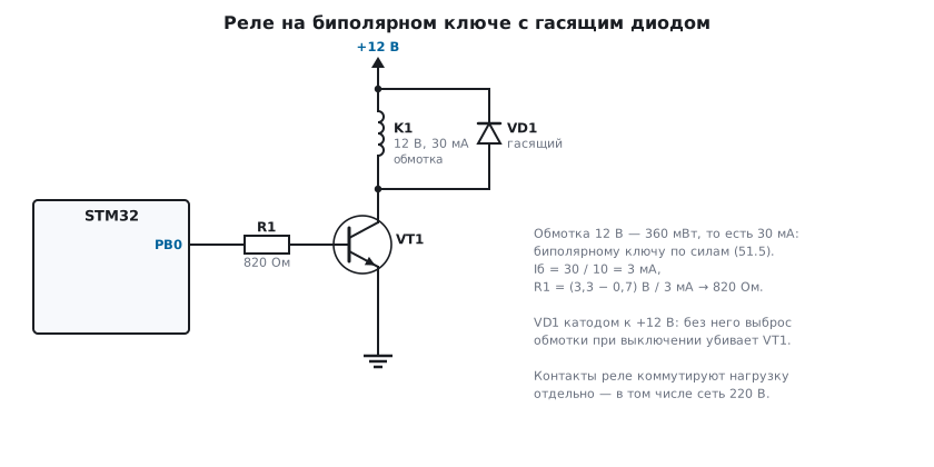
A solid-state relay is an optocoupler plus a triac or MOSFETs: isolation is there, mechanics are not, and the lifetime is not limited by cycles. It costs more, has leakage when off and a voltage drop when on. And what is inside matters. A triac SSR is for AC only: a triac turns off only when the current passes through zero, and on DC, once on, it will never turn off. A "zero-crossing" relay switches the load on only at the start of a half-cycle: it is unsuitable for PWM; it is controlled in whole half-cycles. For DC you take a MOSFET-based relay.
52.7 What to choose
| Load | Switch |
|---|---|
| LED, up to 8–10 mA | directly from the pin (sections 49.3, 49.7) |
| up to 100 mA, infrequent switching | bipolar switch (section 51.5) |
| amps, low frequency | logic-level MOSFET, 470 Ω resistor |
| amps, PWM above 150 Hz | MOSFET + gate driver |
| 220 V mains | relay or solid-state relay, always with isolation |
| motor in both directions | bridge with half-bridge drivers |
| galvanic isolation required | relay, solid-state relay or optocoupler + switch |
A separate note on inrush current: a cold incandescent lamp has a resistance ten times lower than when hot, a motor at start-up draws a multiple of its running current, a capacitive load is almost a short circuit for an instant. A switch is chosen for the inrush current, not the running current.
An inductive load under PWM — a motor, a solenoid, a valve — needs a diode across the load, and at tens of kilohertz only a Schottky or a fast-recovery one. An ordinary rectifier diode recovers in microseconds (in the model of section 169.4 — 3 µs): on every turn-on of the switch reverse current flows through it, and the switch heats up "for no reason". The body diode of the low-side transistor sits across the switch, not the load, and does not do this job.
52.8 Pitfalls
The MOSFET heats up although the current is small. An ordinary one was used instead of a logic-level transistor: with 3.3 V on the gate it is only partly on.
The transistor burned out on the very first PWM. Switching losses: a slow edge from a pin at high frequency.
The load turns on by itself at power-up. No gate pull-down: before initialization the pin is an input.
The motor runs, but the transistor is red-hot. Inrush current, switching losses or a slow diode across the motor (52.7); check the edge with an oscilloscope and calculate I²R at the real current.
A high-side N-channel switch does not turn on. That is expected — you need a bootstrap driver or a P-channel one.
A high-side switch on a half-bridge driver turns off by itself at 100 % duty. The bootstrap capacitor is recharged only while the low-side switch is on; leave a gap in every period or take a driver with a charge pump.
The relay "chatters" when switching on. The supply sags from the coil's inrush current — power the coil separately from the logic.
The microcontroller resets when switching. A spike from the inductance, a ground shared with the power circuit, no decoupling — route power and logic separately (section 49.8).
The relay stopped switching after half a year. Contact lifetime: count the number of operations per day.
The MOSFET "won't turn off". The gate discharges through too large a resistor, or the drain-gate capacitance pulls the gate back up on a fast edge — you need a driver with active pull-down.
52.9 Summary
- At 5 A a bipolar switch loses 3.5 W, a relay contact 1.25 W, a MOSFET 0.55 W; MOSFET losses grow as the square of the current and double with temperature.
- The gate is a 48 nC capacitor: from a pin it charges in 6 µs, from a 1 A driver in 48 ns.
- A slow edge at 20 kHz costs 7.2 W against 0.06 W with a driver; the "no driver" boundary is about 150 Hz.
- A gate resistor driven from a pin — no less than 470 Ω; a gate-to-source pull-down is mandatory.
- An ordinary MOSFET with 3.3 V on the gate is almost off: take one
whose channel resistance is specified at 2.5–2.7 V; the threshold
Vgs(th)is no good for choosing. - A high-side N-channel switch needs a voltage above the load supply — a bootstrap driver (cannot hold 100 % duty), one with a charge pump, or a P-channel transistor.
- A relay gives isolation and a versatile contact at the cost of 360 mW, 10 ms and a lifetime of 100000 cycles.
- A switch is chosen for the inrush current, not the running current.
Next: section 53 "Power supplies" — where the thing we have been switching all along comes from.