 Embedded HandbookApps
53. Power supplies
A microcontroller needs 3.3 volts — smooth, with no dips and no noise. Everything between the wall socket (or a battery) and its supply pin is the power supply. This section covers what it is built from, how much heat each option produces, why a 470 µF capacitor is sometimes useless and why the length of the trace to the decoupling capacitor matters more than its value.
Terms used in the documentation
Term Meaning rectifier, bridge rectifier converts AC to pulsating DC; a four-diode bridge smoothing / bulk capacitor the large capacitor after the rectifier ripple the residual AC on a DC rail linear regulator a regulator that burns the excess voltage as heat low-dropout regulator (LDO) a linear regulator that needs little headroom switching regulator, buck / boost a converter that moves energy in portions; step-down / step-up efficiency output power divided by input power dropout voltage the minimum input-output difference quiescent current (Iq) the regulator's own current consumption thermal resistance (°C/W) temperature rise per watt dissipated decoupling / bypass capacitor a small capacitor right at the supply pin inrush current current surge at switch-on isolated / non-isolated with / without galvanic isolation self-discharge the battery losing charge on its own
53.1 What a power supply consists of
The classic chain from the mains: transformer → rectifier → smoothing capacitor → regulator → decoupling on the board. Each link solves its own task, and something is lost at each one.
A switch-mode supply is built differently — the conversion runs at a high frequency there — but the end of the chain is the same: a regulator and decoupling.
53.2 Rectifier and smoothing capacitor
From a 12 V AC transformer, after the bridge you are left with 14.8 V at the peak: minus two diode drops (section 51.1), because the current flows through two diodes at once.
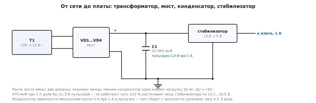
Next comes the capacitor. Between the peaks it feeds the load on its own —
with a 50 Hz mains and full-wave rectification that is 10 ms.
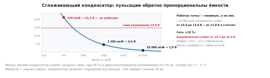
Hence the ripple: ΔU = I · t / C.
| Capacitance | Ripple at 1 A |
|---|---|
| 470 µF | 21.3 V |
| 2200 µF | 4.5 V |
| 10000 µF | 1.0 V |
470 µF at an ampere simply does not work: the calculated ripple is larger than the voltage itself. The capacitance is proportional to the current and inversely proportional to the allowed ripple: at 100 mA 1000 µF is enough, and to cut the ripple in half you need twice the capacitance.
⚠️ Calculate from the minimum, not the peak. With 10000 µF the voltage swings from 14.8 to 13.8 V. It is 13.8 V that is the operating point for the regulator, and it is from this value that its losses are calculated.
A simulation of the same rectifier gives 14.7 and 13.9 V: the formula I · t / C is
an upper-bound estimate; the capacitor starts recharging before the
full 10 ms have passed.
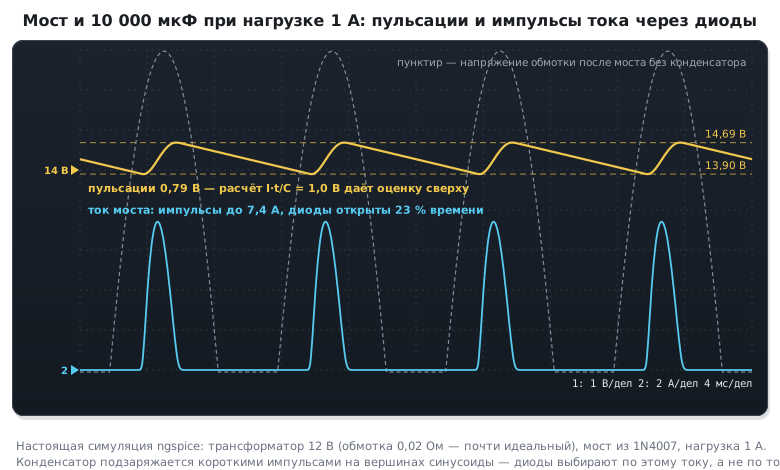
The current through the diodes is much larger than the load current. The capacitor charges in short pulses — a diode is on for roughly a fifth of the time, so with 1 A in the load the bridge carries pulses of about 5 A. The average current stays 1 A, but the heating is done by the RMS value of the pulses — about 2.2 A (5 × √0.2). That is why a bridge is chosen with a 2–3× margin on average current, and you check that the pulses fit within the repetitive peak current from the datasheet. For the same reason a transformer for 1 A of DC needs about 22 VA, not 12.
The mains is not constant. With a ±10 % deviation the rectified voltage swings from 13.1 to 16.5 V — a spread of 3.4 V that the regulator has to handle at both ends.
53.3 The linear regulator: simple and hot
A linear regulator is a controlled resistance: it turns the excess voltage into heat. The input current equals the output current.
A 13.8 → 5 V regulator at 1 A:
- dissipates 8.8 W;
- its efficiency is 36 %;
- 1.8 times more goes into heat than into the load.
Without a heatsink the package has a thermal resistance of about 60 °C/W — that is a 526 °C temperature rise, i.e. instant destruction. To keep the die below 125 °C at 40 °C ambient, the whole thermal path from the die to the air must be no worse than 9.7 °C/W. From it you subtract "junction to case" (3…5 °C/W for a TO-220 package, per the device datasheet) and "case to heatsink" (pad and paste, about 1 °C/W). That leaves 3.7…5.7 °C/W for the heatsink itself — that is already a large finned part. A 9.7 °C/W heatsink would bring the die to 178 °C.
The same device looks completely different under other conditions:
| Task | Losses | Heatsink |
|---|---|---|
| 13.8 → 5 V, 1 A | 8.8 W | mandatory, a serious one |
| 13.8 → 5 V, 50 mA | 0.44 W | not needed |
| 5 → 3.3 V, 100 mA | 170 mW | not needed |
The last row is the most common use on a microcontroller board: a small difference, a small current, an efficiency of 66 %, but no noise at all and three parts around it. That is exactly where the linear regulator is good.
Two parameters people forget: the dropout voltage (an ordinary one needs 2 V, a low-dropout one 0.2 V; with battery power this is decisive) and the quiescent current, which flows always, even with no load — for a sleeping device it can turn out to be the main consumer.
53.4 The switching converter: more complex and cooler
A switching converter does not burn the excess but moves energy in portions through an inductor (section 46.3). At 90 % efficiency the same 5 V / 1 A supply loses 0.56 W instead of 8.8 — 15.8 times less. The temperature rise without a heatsink is 33 °C; no heatsink is needed at all.
One more difference that is often missed: the current drawn from the source. The linear one draws exactly the load current — 1.00 A. The switching one, at the same input voltage, draws 0.40 A, 2.5 times less: it converts the voltage rather than burning the difference. For battery power or a low-current source this is the decisive argument.
The price is noise. The converter runs at hundreds of kilohertz and makes noise exactly there: both on the supply and over the air. The cure is an output filter: a 10 µH inductor and a 22 µF capacitor give a cut-off of about 11 kHz and an attenuation of roughly 2170 times at 500 kHz. But right at the cut-off frequency an LC filter has a resonant peak: with ceramics it is almost lossless, and noise around 11 kHz gets amplified. It is damped with a series resistance (an electrolytic with noticeable ESR in parallel with the ceramic, or a resistor of a fraction of an ohm), and the filter is placed after the point from which the converter takes its feedback. Plus careful layout: the converter's power loop as short as possible.
What to choose. A large difference or a noticeable current — switching. A small difference, a small current and a clean supply matters (ADC, analog circuits) — linear. Often both are used: the switching one makes 5 V from 12, the linear one clean 3.3 V from 5.
53.5 Decoupling: why 100 nF at every pin
A microcontroller does not draw current evenly: every switching event inside
causes a surge. Say 50 mA in 5 ns with an allowed dip of 50 mV —
then by the formula C = I·t/ΔU you need only 5 nF. People fit 100 nF, a margin
of twenty times. Why?
Because the issue is not capacitance but trace inductance. A trace
gives about 1 nH per millimetre; ten millimetres from the capacitor to the
pin is 10 nH and a dip of U = L·di/dt = 0.1 V on the same surge,
twice the allowed value. Every extra millimetre is a 10 mV dip.
Hence rules that look like ritual but have a calculation behind them:
- a 100 nF capacitor at every supply pin, physically close — millimetres, not centimetres;
- a via to ground right at the capacitor;
- one shared 4.7…10 µF capacitor for the whole chip — it handles slow surges, and the 100 nF ones handle fast ones;
- separate decoupling for the analog supply, often with an inductor or a ferrite bead.
53.6 Battery power
The capacity of a typical lithium coin cell is 220 mAh. How long that lasts:
| Average current | Lasts for |
|---|---|
| 10 µA | 917 days (two and a half years) |
| 60 µA | 153 days |
| 1 mA | 9 days |
The difference between the first and the last row is a hundred times, and it is determined not by the electronics but by how much the device sleeps (section 10, section 46.5). The average current is calculated over a cycle: sleep plus rare wake-ups.
The coin cell delivers these 220 mAh only at a low current. The CubeMX power
consumption calculator sets 225 mAh for a CR2032 at a continuous current of up to 3 mA and
a pulse of up to 15 mA. Pulses — a radio transmission, a Flash write, an LED —
drop the cell voltage across its internal resistance, and the more so
the closer the end of discharge, down to the reset threshold (section 61.2). That is why
the pulse is taken from a low-leakage capacitor in parallel with the battery, and the battery
then recharges it at a leisurely pace: a 20 mA pulse lasting 5 ms with a dip of
0.2 V needs C = I · t / ΔU = 500 µF.
There is also a floor: self-discharge of about 1 % a year is 251 nA. Going noticeably below this value is pointless; the battery will discharge by itself anyway.
What matters for battery power: a regulator with a low quiescent current, a low dropout (otherwise half the capacity goes into heat) and no dividers that draw current all the time (section 50.2).
53.7 Safety
A separate word on transformerless supplies — a dropping capacitor straight from the mains. They are cheap and compact, so they show up in household appliances. And they have no galvanic isolation: the whole circuit, including the microcontroller pins and any accessible contact, is at mains potential.
Practical consequences:
- you must not connect a debugger or an oscilloscope with an ordinary probe — you would connect the mains to the ground of the computer and the instrument. Such circuits are debugged by powering them from the mains through an isolation transformer, or with a differential probe and an isolated debugger (section 54);
- any connector accessible from outside must be isolated (optocoupler, transformer, radio link);
- the enclosure — double-insulated only.
For learning and most industrial tasks such a supply is not worth using: a ready-made isolated module costs little and removes a whole class of problems.
53.8 Pitfalls
The device resets under load. The supply sags: a small smoothing capacitor, thin traces or a supply shared with the power section.
The regulator is red-hot. Calculate (Vin − Vout) × I. Most likely
you need a switching converter or a heatsink.
The regulator outputs less than its rating. Not enough input-output headroom: with 5 V at the input an ordinary 5 V regulator will not deliver; you need a low-dropout one.
Ripple on the ADC output. Noise from the switching converter, a supply shared with the analog section, no decoupling.
The bridge heats up although the load is small. The capacitor charges in pulses five times the load current; the RMS current of the bridge is more than twice the average.
The coin cell died in a week instead of a year. Average current: a divider, a pull-up, an indicator LED, the regulator's quiescent current, too little sleep.
The board works until you connect the debugger. A sign of a supply without isolation — stop and check before something burns.
The microcontroller misbehaves unpredictably. Decoupling: the 100 nF is far from the pin or missing altogether.
53.9 Summary
- After the bridge, 12 V AC leaves 14.8 V at the peak; calculate from the ripple minimum, not the peak.
- Ripple is
ΔU = I·t/C, where t = 10 ms: for 1 V at 1 A you need 10000 µF; 470 µF is useless at that current. - The bridge carries pulses five times the load current: the average current is 1 A, the RMS about 2.2 A; the transformer must be rated 22 VA for 1 A of DC.
- A linear regulator with an 8.8 V difference and 1 A dissipates 8.8 W (36 % efficiency) and needs a thermal path of 9.7 °C/W — the heatsink itself gets 3.7…5.7 °C/W; at 5 → 3.3 V and 100 mA it is 170 mW and no heatsink at all.
- A switching converter loses 0.56 W instead of 8.8 and draws 0.40 A from the source instead of 1.00, but makes noise at the conversion frequency.
- Decoupling: 100 nF right at every supply pin — what matters is the trace inductance (1 nH/mm), not the value.
- A 220 mAh battery: 917 days at 10 µA, 9 days at 1 mA; the floor is set by the 251 nA self-discharge.
- A transformerless supply has no isolation — you must connect neither a debugger nor an oscilloscope to it.
Next: section 54 "Galvanic isolation" — how to break the electrical connection while keeping the signal path.