 Embedded HandbookApps
54. Galvanic isolation
Isolation means the signal gets through but no current flows. Between the two parts of the circuit there is no electrical connection at all: they are coupled by light, by a magnetic field or by an electric field across a barrier.
You need it in three cases: when there is a dangerous voltage on the other side and a person must be protected; when the other side has its own ground and the two must not be connected; when expensive equipment has to be protected from whatever happens to a cheap sensor. This section covers what to isolate with, how to calculate the surrounding circuit and why isolation is never complete.
Terms used in the documentation
Term Meaning galvanic isolation no conductive path between two circuits optocoupler, optoisolator an LED and a photodetector in one package current transfer ratio (CTR) output current divided by LED current digital isolator a chip passing logic signals across a capacitive or magnetic barrier isolated DC/DC converter a power converter with a transformer barrier ground loop current flowing through a signal line between two grounds working / test voltage continuous rating / short factory test rating basic / reinforced insulation single-level / double-level protection creepage / clearance distance along the surface / distance through air common-mode transient immunity (CMTI) tolerance to fast jumps of one side's potential barrier capacitance the parasitic capacitance between the two sides
54.1 Why break the circuit
Safety. If the mains is on the other side, isolation is the only thing standing between it and a person. The requirements here are not recommendations.
Different grounds. A sensor a hundred metres away, a drive in the next cabinet, a bus between buildings — each has its own ground, and the potential difference between them can be tens of volts, and in a fault, hundreds. Connect them with a wire and you get current in the signal line: that is a ground loop. It spoils measurements and sometimes the equipment.
Damage containment. An industrial 24 V input to which anything at all gets connected; a line that leaves the enclosure; a circuit with inductance and large currents. Isolation turns "the whole board burned" into "an optocoupler worth twenty roubles burned".
54.2 The optocoupler: an LED and a photodetector in one package
Inside there is an LED and a phototransistor separated by a transparent insulator. Current through the LED causes current in the transistor; electrically the two sides are not connected.
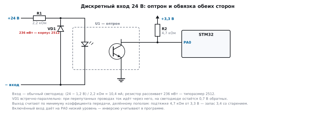
The input is calculated like an ordinary LED (section 49.3), with a drop of about 1.2 V; when driven from a microcontroller pin you also subtract the 0.4 V that drops across the pin itself:
| Source | Resistor | Current | Power in the resistor |
|---|---|---|---|
| 3.3 V pin | 220 Ω | 7.7 mA | 13 mW |
| 24 V industrial input | 2.2 kΩ | 10.4 mA | 236 mW |
The second row is a typical trap: at 24 V the resistor dissipates 236 mW, almost a quarter of a watt, and when the supply rises to 30 V it is already 377 mW. Sizes 0603 rated 100 mW and 0805 rated 125 mW will burn here, a 1206 rated 250 mW works at 24 V at its limit and is overloaded at 30 V (section 49.6). You need a 2512 rated 1 W — or a lower current: with 5.6 kΩ that is 4.1 mA and 93 mW at 24 V, 148 mW at 30 V, but then the optocoupler output must be recalculated for that current. The limits must be checked too: when the supply sags to 18 V the current drops to 7.6 mA, when it rises to 30 V it grows to 13.1 mA — both values are acceptable.
Reverse polarity. An optocoupler LED withstands only a few volts in reverse, and the first thing an industrial input gets is swapped wires — 24 V the wrong way round is far beyond that limit. That is why an ordinary diode is placed anti-parallel to the LED: on reverse polarity the current flows through it, (24 − 0.7) / 2.2 kΩ = 10.6 mA, and the LED sees only 0.7 V in the reverse direction. For an AC input you take an optocoupler with two anti-parallel LEDs.
The output is described by the current transfer ratio — the ratio of the transistor current to the LED current. And here is the main point:
⚠️ The current transfer ratio ranges from 50 to 600 % — twelve times between units of the same batch. And it drops roughly by half over the service life. The circuit is calculated from the minimum, further divided by two.
For our example: with 7.7 mA at the input the minimum output is 3.86 mA. A 4.7 kΩ pull-up from 5 V needs only 1064 µA, i.e. a margin of 3.6; allowing for ageing — 1.8. Enough, though with nothing to spare. If the output is read by a microcontroller powered from 3.3 V, the pull-up goes to its supply: to 5 V only on a 5 V tolerant pin (section 62.1). From 3.3 V the pull-up takes 0.70 mA, the margin is 5.5, with ageing 2.8.
And if you calculated from the typical ratio of 200 %, the margin would look sevenfold — and after a few years the device would start failing for no visible reason.
54.3 Speed: the optocoupler's main limitation
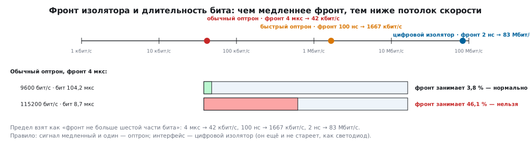
An ordinary transistor-output optocoupler has an edge of about 4 µs — but that is how the datasheet specifies it, with a 100 Ω load. With the 4.7 kΩ pull-up from 54.2 the turn-off edge is several times longer: the phototransistor capacitance recharges through the pull-up. So the numbers below are a ceiling, not the working speed; for speed you take a smaller pull-up, as far as the current allowed by the transfer ratio permits, and look at the edge with an oscilloscope. What the 4 µs itself means:
| Speed | Bit duration | The edge takes |
|---|---|---|
| 9600 bit/s | 104 µs | 3.8 % — fine |
| 115200 bit/s | 8.7 µs | 46 % — not allowed |
The limiting frequency for such an optocoupler is about 42 kHz. For a slow interface, a button, an "alarm" signal that is enough; for UART at 115200, SPI or CAN it is not.
| Device | Edge | Limit |
|---|---|---|
| ordinary optocoupler | 4 µs | 42 kbit/s |
| fast optocoupler | 100 ns | 1667 kbit/s |
| digital isolator | 2 ns | 83 Mbit/s |
A digital isolator passes the signal not by light but across a capacitive or magnetic barrier. It is orders of magnitude faster, does not age the way an LED does, needs no transfer ratio calculation (logic level at the input, logic level at the output) and often contains several channels in one package, including channels in opposite directions. It has two drawbacks. It costs more than an optocoupler. And it needs a supply on both sides of the barrier: an optocoupler LED on the input side is fed by the signal current itself, while an ordinary isolator there needs its own source (54.4). That is why 24 V digital inputs are usually built with optocouplers, and interfaces with isolators.
The rule of thumb: a slow single signal — an optocoupler; an interface — a digital isolator.
54.4 Isolated power
An isolator passes the signal but not energy. So the far side must have its own supply — otherwise there is no isolation.
The options: a separate source (if one is already there), power from the line itself (that is how current loops work), or an isolated converter — a small module with a transformer inside.
The budget for an isolated RS-485 port:
| Consumer | Current |
|---|---|
| transceiver | 30 mA |
| digital isolator | 7 mA |
| line bias resistors | 10 mA |
| indicator LED | 5 mA |
| total | 52 mA |
A 1 W module gives 200 mA at 5 V — a margin of 3.8 times. From the main supply it will draw no less than 65 mA: it is loaded to a quarter, and the 80 % efficiency of such a module applies at full load; at a quarter it is lower. And the output of an unregulated module at light load rises above 5 V — check it against what the transceiver allows.
A caveat right here: isolated converters are the same switching supplies, and they are noisy (section 53.4). On sensitive boards they are filtered and laid out carefully.
54.5 How many volts the isolation withstands
Datasheets show two different numbers, and confusing them is expensive:
- test voltage (for example, 2500 V) — the device withstands it for one minute during the factory test;
- working voltage (for example, 250 V) — what can be applied continuously over the whole life of the product.
The ratio is roughly tenfold, and it is not a "just in case" margin but two different quantities: one is about short-term withstand, the other about lifetime.
Clearances on the board are as important as the device itself. For a 250 V mains basic insulation requires about 4 mm along the surface, reinforced insulation 8 mm. A DIP optocoupler package gives about 7 mm — just barely, and you must not route a trace under it: it would reduce the whole gap to the distance between the trace and a pin. Where space is short, a slot is milled under the package — the creepage path then runs along its walls and gets longer.
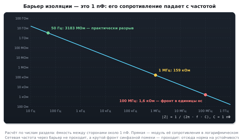
Isolation is not absolute. There is always capacitance between the sides — about 1 pF. At 50 Hz that is 3183 MΩ, practically an open circuit. But at a megahertz it is already hundreds of kilohms: fast noise passes through the barrier as if nothing were there. That is why isolators are specified for common-mode transient immunity: how fast the potential of one side may "jump" relative to the other without distorting the signal.
And the main path for noise through the barrier is often not the signal isolator at all, but the isolated power converter (54.4): the capacitance between the windings of its transformer is tens of picofarads. 50 pF at a megahertz is 3.2 kΩ, fifty times less than for a 1 pF barrier, and the common-mode current of its own switching flows through it. For sensitive circuits you choose a converter with a low barrier capacitance.
54.6 What gets isolated in practice
| What | With what |
|---|---|
| 24 V digital input | optocoupler + 2.2 kΩ 2512 resistor |
| digital output to a relay | optocoupler or isolated driver |
| RS-485, CAN | digital isolator + isolated converter |
| USB to a computer | USB isolator or isolation at protocol level |
| current measurement in a power circuit | isolated amplifier or Hall sensor |
| triac control on the mains | zero-crossing opto-triac |
| debug port in a mains-powered product | not isolated — simply not connected |
The last row is more serious than it looks: if the supply has no isolation (section 53.7), connecting a debugger connects the mains to the computer's ground.
54.7 Pitfalls
The optocoupler stopped switching after a year or two. The transfer ratio dropped over time, and the calculation used the typical value. Calculate from the minimum and divide by two.
The resistor on the 24 V input chars. A quarter of a watt in a package rated 100 mW.
UART through an optocoupler works at 9600 and fails at 115200. A 4 µs edge. Use a fast optocoupler or a digital isolator.
The signal was isolated, but the grounds are still connected. Through the supply, through the cable shield, through the enclosure mounting. Isolation works only if all paths are broken.
The isolated side has no power. Forgot that an isolator passes signal, not energy.
Noise passes through the isolation. Barrier capacitance: at high frequency it conducts. Look at the common-mode transient immunity and do not run power circuits next to the barrier.
A trace under the optocoupler package. Formally the gap is provided by the package, in fact it is set by the distance to the trace.
The signal got inverted. With an optocoupler that has a pull-up on its output, a lit LED gives a low level. This is normal, but the firmware has to account for it.
54.8 Summary
- Isolation is needed for safety, for different grounds and for damage containment; it breaks the current but passes the signal.
- The optocoupler input is calculated like an LED; a 2.2 kΩ resistor dissipates 236 mW at 24 V and 377 mW at 30 V — that calls for size 2512.
- The transfer ratio varies twelvefold and halves over the service life: calculate from the minimum with an ageing allowance.
- An ordinary optocoupler is limited to about 42 kbit/s; for interfaces use a digital isolator (up to tens of Mbit/s).
- An isolator does not pass energy: the far side needs its own source; the budget of an isolated RS-485 port is about 52 mA.
- Test voltage and working voltage are different quantities, differing roughly tenfold.
- Clearances on the board matter no less than the device: 8 mm for reinforced insulation at 250 V, no traces under the package.
- Barrier capacitance is about 1 pF: at high frequency the isolation conducts.
Next: section 55 "Linear regulators" — a detailed look at the most common power chip on the board.