 Embedded HandbookApps
50а. Circuits in frequency: magnitude response, phase response and the Bode plot
Section 50 looked at the RC circuit in time, and in frequency only through the cutoff formula and the "20 dB per decade" rule. Here is the same circuit in full: how amplitude and phase change with frequency, why they are drawn in decibels on a logarithmic axis, what happens when there are two stages, how an RC in front of the ADC helps and how it does not help, how a filter on an op-amp behaves, and how to measure a frequency response with the microcontroller itself — the DAC outputs a sine, the ADC measures the response.
References: reference manual RM0090 Rev 19 (fields TSEL1 in DAC_CR and EXTSEL in ADC_CR2) and datasheet DS8626 Rev 9 for the F405/407 (DAC output buffer, ADC sampling capacitance) — both from the Keil pack. Every circuit is computed three times: with a formula, with ngspice 39 (image stm-lab:1, op-amp — the macromodel of section 164) and with a measurement model on a PC that runs the same C code as the firmware.
Terms used in the documentation
Term Meaning frequency response how a circuit responds to sines of different frequencies magnitude response gain versus frequency phase response phase shift versus frequency Bode plot magnitude and phase plotted on a logarithmic frequency axis cutoff (corner) frequency frequency where the response bends down roll-off, dB/decade rate of fall of the response above cutoff aliasing high frequencies appearing as low ones after sampling anti-aliasing filter filter in front of the ADC that prevents aliasing frequency sweep stepping a test sine through a range of frequencies zero-order hold holding each sample as a step (the DAC staircase)
50а.1 What magnitude and phase responses show
A sine is applied to the input of a linear circuit. At the output there is a sine of the same frequency, but of a different amplitude and shifted in time. The ratio of the amplitudes is the magnitude response, the shift in degrees of the period is the phase response. Both depend only on frequency, so it is convenient to write them as one complex number. For the RC circuit of section 50:
H(f) = 1 / (1 + j · f / fc),   fc = 1 / (2 · π · R · C)
|H| — во сколько раз ослаблена амплитуда, arg H — сдвиг фазы
Amplitude is expressed in decibels: 20 · lg(K). This is more convenient for two reasons:
circuits connected one after another multiply their gains, while decibels
simply add up; and one graph fits both 1 and 0.0001.
Reference points worth remembering:
| Ratio | Decibels |
|---|---|
| 0.707 (square root of one half) | −3.01 |
| 0.5 | −6.02 |
| 0.1 | −20 |
| 0.01 | −40 |
| 2 | +6.02 |
| 10 | +20 |
Frequency is plotted on a logarithmic axis: a decade is a step of 10 times, an octave of 2 times. A roll-off of 20 dB per decade is the same as 6.02 dB per octave.
50а.2 Bode plot of an RC circuit
Take R = 10 kΩ and C = 10 nF: the cutoff is 1591.5 Hz. The formula and ngspice give the same result:
| Frequency | Magnitude, dB | Phase |
|---|---|---|
| 0.1 of cutoff | −0.043 | −5.71° |
| 0.5 of cutoff | −0.969 | −26.57° |
| cutoff | −3.010 | −45.00° |
| 2 × cutoff | −6.990 | −63.43° |
| 10 × cutoff | −20.04 | −84.29° |
| 100 × cutoff | −40.00 | −89.43° |
ngspice finds the −3.01 dB point exactly at 1591.5 Hz, the phase at cutoff is −45.00°, and at ten times the cutoff −20.04 dB and −84.29°.
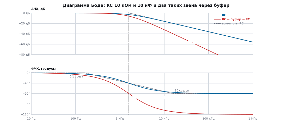
The curve hardly needs to be computed — it is replaced by straight lines (asymptotes):
- Magnitude — zero decibels up to the cutoff, then a straight line down by 20 dB per decade. The lines are most wrong at the cutoff itself — by 3.01 dB; at half the cutoff and at twice the cutoff — by 0.97 dB.
- Phase — 0° up to a tenth of the cutoff, −90° after ten times the cutoff, and between them a straight line through −45° at the cutoff. The largest error is 5.71°, at the ends of the segment.
At low frequency the phase is simply a delay. At 50 Hz the circuit shifts the signal by −1.80°, that is by 99.97 µs, and the RC time constant is 100 µs: below the cutoff an RC circuit lags by τ without distorting the waveform.
50а.3 Second order: two stages in a row
Put two identical RC stages in a row. If there is a buffer between them
(an op-amp voltage follower), the transfer functions simply multiply: H². The roll-off
becomes 40 dB per decade (ngspice: −40.09 dB at ten times the cutoff,
−80.00 dB at a hundred times), the phase at cutoff is −90° and goes further towards −180°. But
the bandwidth also narrows: −3 dB is now not at 1591.5 but at 1024.3 Hz —
at 0.6436 of the single-stage cutoff, and at the cutoff itself it is already −6.02 dB.
Without a buffer the second stage loads the first, and the result is a different circuit:
H(x) = 1 / (1 − x² + 3 · j · x), x = f / fc
Its Q factor is 1/3, and the bandwidth is narrower still: −3 dB at 0.3742 of the cutoff, 595.6 Hz (ngspice gives the same 595.6 Hz). At the cutoff it is −9.54 dB instead of −6.02 with a buffer, phase −90°. Far from the cutoff there is no difference — the same −40 dB per decade (−80.00 dB at a hundred times the cutoff) and the phase towards −180° (−178.28° at the same point).
Two RCs in a row are the simplest second-order filter, but also the most sluggish: its knee is gentle. A sharp knee at the same order is given by the Sallen–Key circuit from section 178, which also explains how to choose the Q factor.
50а.4 RC in front of the ADC and aliasing
An ADC that takes samples at a rate fs cannot tell frequency f from
|f − k · fs|. At fs = 10 kHz a 9 kHz interference looks in the samples like
an honest 1 kHz signal, and it can no longer be filtered out in software. So
everything above fs/2 must be suppressed before the ADC.
How much our RC circuit with a 1.59 kHz cutoff gives:
| Interference | RC | Two RCs through a buffer |
|---|---|---|
| 5 kHz (half of fs) | −10.36 dB, 3.30 times | −20.72 dB |
| 9 kHz (seen as 1 kHz) | −15.18 dB, 5.74 times | −30.36 dB |
ngspice confirms all four numbers. But for full-amplitude interference to fall below half an LSB of a 12-bit ADC, you need 78.3 dB. Conclusion: a single RC at the ADC input is not an anti-aliasing filter. Its job is to hold charge for the sampling capacitor (on the F407 it is 4 pF per DS8626, in detail — 50.6 and 180) and to remove part of the broadband noise. Aliasing is prevented differently: raise fs to several times the signal bandwidth and filter digitally, or use a high-order filter (178.5).
50а.5 A filter on an op-amp: gain and cutoff at once
An inverting amplifier with a capacitor in parallel with the feedback
resistor: R1 = 10 kΩ, R2 = 100 kΩ, C = 1 nF. Gain −R2/R1 = −10
(+20 dB), cutoff 1 / (2π · R2 · C) — the same 1591.5 Hz. The supply is
single 3.3 V, the reference is the midpoint 1.65 V (section 162).
| Frequency | Ideal op-amp | Op-amp with 1 MHz bandwidth (ngspice) |
|---|---|---|
| 10 Hz | 20.00 dB, 179.6° | 20.00 dB, 179.6° |
| 1591.5 Hz | 16.99 dB, 135.0° | 16.92 dB, 134.5° |
| 100 kHz | −15.96 dB, 90.9° | −16.10 dB, 85.2° |
| 1 MHz | −35.96 dB, 90.1° | −36.03 dB, 37.3° |
The phase here is counted including the inversion: 180° at low frequency, towards 90° above the cutoff. The −3 dB level from 20 dB is 16.99 dB; a real op-amp reaches it at 1566 Hz, 1.6 % below the calculated value: the amplifier itself has a finite bandwidth (the gain-bandwidth product is 1 MHz in the model), and at frequencies where the excess gain is small it adds its own pole. This is clearly visible in the phase: at 1 MHz the ideal holds 90°, while the model is already at 37° — the filter becomes second-order. The rule is simple: the op-amp bandwidth must be much greater than the product of gain and cutoff (here 10 · 1.59 kHz), otherwise the cutoff and the roll-off will shift. On phase margin — section 163.
50а.6 Measuring the frequency response with the microcontroller itself
You do not need a generator and an oscilloscope: the F407 has a DAC and an ADC. The DAC outputs a sine
from a table of M points, the circuit passes it, the ADC samples the output.
Both are started by one event — the TIM2 update: in RM0090 this is TSEL1 =
100 in DAC_CR and EXTSEL = 0110 in ADC_CR2. The timer sets the sampling
rate fs, and the sine frequency is fs / M.
void bode_trigger_setup(uint32_t arr)
{
    TIM2->ARR = arr;                                            /* fs = 84 МГц / (ARR + 1) */
    TIM2->CR2 = TIM_CR2_MMS_1;
    DAC->CR = DAC_CR_TSEL1_2 | DAC_CR_TEN1 | DAC_CR_DMAEN1 | DAC_CR_EN1;
    ADC1->CR2 = ADC_CR2_EXTEN_0 | ADC_CR2_EXTSEL_1 | ADC_CR2_EXTSEL_2 | ADC_CR2_DMA | ADC_CR2_DDS | ADC_CR2_ADON;
    TIM2->CR1 = TIM_CR1_CEN;
}
The APB1 bus timers count from 84 MHz with a 168 MHz core (section 13). DMA streams for the table and the samples are as in section 9. After waiting eight periods for settling, take 16 whole periods and correlate them with reference sine and cosine of the same phase as the DAC table:
    for (int k = 0; k < n; k++) {
        float x = (float)adc[k] - mean;
        i += x * s_tab[k % m];
        q += x * c_tab[k % m];
    }
    float amp = 2.0f * sqrtf(i * i + q * q) / (float)n;
    float ph = atan2f(q, i) * 57.295780f;
    if (zoh) {
        const float x = 3.14159265f / (float)m;
        amp /= sinf(x) / x;                    /* ступенька ослабляет первую гармонику: sinc */
        ph += 180.0f / (float)m;               /* и запаздывает на полшага */
    }
The DC component (the midpoint 2048) is subtracted, and what remains is the amplitude and
phase of the first harmonic. The zoh correction is needed because the DAC outputs not a
sine but steps: at M = 32 they attenuate the first harmonic by a factor of 0.99839
(−0.0140 dB) and shift it by half a step — 5.625°. Without the correction, the phase response
at 32 points and frequencies from 1 kHz is wrong by 5.3–5.9°.
The PC model compiles the same file with gcc and feeds it samples from an exact model of the circuit (DAC staircase, RC, sampling at the trigger instant, 12 bits). The result:
- Always 32 points per period — good at high frequencies, bad at low ones. At 100 Hz the sampling rate is 3.2 kHz, the 312 µs step is three times longer than τ = 100 µs, the circuit almost settles on every step, and the half-step correction stops working: phase −6.14° against −3.60° by the formula.
- As many points as needed to keep fs no lower than 100 kHz (up to 1024 per period) — from 100 Hz to 10 kHz the error is no more than 0.03 dB and 0.3° for both circuits, the single RC and the two through a buffer. ADC noise of 1 LSB shifts the measurement by no more than 0.012 dB and 0.3°, and the error stays within the same limits: correlation over 16 periods averages it out.
Numbers to check on the board: the DAC table 448…3648 lies inside 0x0E0…0xF1C, where the DAC buffer per DS8626 gives the full swing; the datasheet allows updating the DAC up to 1 million times per second for small steps, and our fs is no higher than 320 kHz (but at the upper frequencies the table steps are large — hundreds of codes, and buffer settling on them is not verified here); the buffer load must be no less than 5 kΩ, and the input of the RC circuit is never less than R = 10 kΩ. At 1591.5 Hz with M = 32 the timer divider comes out at 1649, and the frequency is 1591.87 Hz — compute the formula for that one, not for the requested one. Memory at M = 1024: reference sine and cosine — 8 KB, DAC table — 2 KB, 16 periods of samples — 32 KB.
50а.7 Pitfalls
Two stages of 1.59 kHz each, but the cutoff is at 1 kHz. −3 dB of the cascade is not the cutoff of each stage: through a buffer 1024 Hz, without a buffer 596 Hz. Calculate the overall magnitude response, not the stages separately.
A second RC stage without a buffer is a different circuit. At the cutoff −9.54 dB instead of −6.02: the second stage loads the first. Either a buffer between the stages, or calculate the cascade as one circuit.
The RC at the ADC input is taken for aliasing protection. At 9 kHz with fs = 10 kHz it attenuates the interference only 5.74 times, while 78 dB are needed. The interference lands in the signal band for good.
The phase is measured through the DAC without the staircase correction. At 32 points — an extra 5.6° of lag that is not in the circuit.
A sweep with 32 points at low frequencies. When the DAC step is longer than the circuit's time constant, the "sine plus half a step" model breaks down; the phase drifts by degrees. Keep fs well above the cutoff by increasing the number of points.
Correlation over a non-integer number of periods. The reference sine and cosine stop being orthogonal, and the amplitude and phase drift depending on where the record is cut. The number of samples must be exactly M × the number of periods.
Expecting an op-amp filter to roll off forever. At frequencies where the op-amp bandwidth runs out, its own pole is added: at 1 MHz the phase is 37° instead of 90°, and the cutoff has moved down by 1.6 %.
50а.8 Summary
- Decibels: 0.707 — −3.01; 0.5 — −6.02; 0.1 — −20; a first-order circuit rolls off at 20 dB per decade (6.02 per octave).
- RC of 10 kΩ and 10 nF: cutoff 1591.5 Hz, with −3.01 dB and −45° there; the asymptotes are wrong by no more than 3.01 dB and 5.71°; below the cutoff the circuit is a delay of τ = 100 µs.
- Two stages through a buffer: 40 dB per decade, −3 dB at 1024.3 Hz; without a buffer 595.6 Hz and −9.54 dB at the cutoff.
- A single RC is powerless against aliasing: 5.74 times at 9 kHz when 78.3 dB are needed.
- An op-amp filter with a gain of 10 and an op-amp bandwidth of 1 MHz: cutoff 1566 Hz instead of 1591.5, at 1 MHz the phase is 37° instead of 90°.
- The frequency response is measured with a DAC → circuit → ADC chain from one timer; with the staircase correction and fs no lower than 100 kHz the error is up to 0.03 dB and 0.3°.
Full source code
bode50b.c — magnitude and phase response of a circuit, measured with the microcontroller's DAC and ADC.
/* bode50b.c — раздел 50а: АЧХ и ФЧХ цепи, снятые самим микроконтроллером.
 *
 * ЦАП выдаёт синус по таблице из m точек, АЦП берёт отсчёт с выхода цепи по тому же
 * запуску таймера. После целого числа периодов свёртка с опорными sin и cos даёт амплитуду
 * и фазу первой гармоники. Файл собирается двумя способами:
 *   - armclang для STM32F407 (-DSTM32F407xx -include stm32f4xx.h): математика + запуск от TIM2;
 *   - gcc на ПК (bode_host.c включает этот файл): та же математика на отсчётах модели цепи.
 */
#include <stdint.h>
#include <math.h>

#define BODE_MMAX 1024     /* точек синуса на период — не больше */
#define BODE_MID 2048      /* середина шкалы 12 бит */
#define BODE_AMP 1600      /* амплитуда, коды: 448…3648 — внутри 0x0E0…0xF1C, где буфер ЦАП линеен */

static float s_tab[BODE_MMAX], c_tab[BODE_MMAX];

/* Таблица для ЦАП на m точек и опорные синус и косинус той же фазы. */
void bode_tables(uint16_t *dac, int m)
{
    for (int k = 0; k < m; k++) {
        float w = 6.2831853f * (float)k / (float)m;
        s_tab[k] = sinf(w);
        c_tab[k] = cosf(w);
        dac[k] = (uint16_t)lrintf(BODE_MID + BODE_AMP * s_tab[k]);
    }
}

typedef struct { float gain_db, phase_deg; } bode_point;

/* n отсчётов АЦП — целое число периодов по m точек. zoh = 1: поправка на ступеньку ЦАП. */
bode_point bode_measure(const uint16_t *adc, int n, int m, int zoh)
{
    float mean = 0.0f, i = 0.0f, q = 0.0f;
    for (int k = 0; k < n; k++)
        mean += adc[k];
    mean /= (float)n;
    for (int k = 0; k < n; k++) {
        float x = (float)adc[k] - mean;
        i += x * s_tab[k % m];
        q += x * c_tab[k % m];
    }
    float amp = 2.0f * sqrtf(i * i + q * q) / (float)n;
    float ph = atan2f(q, i) * 57.295780f;
    if (zoh) {
        const float x = 3.14159265f / (float)m;
        amp /= sinf(x) / x;                    /* ступенька ослабляет первую гармонику: sinc */
        ph += 180.0f / (float)m;               /* и запаздывает на полшага */
    }
    bode_point p = { 20.0f * log10f(amp / BODE_AMP), ph };
    return p;
}

#ifdef STM32F407xx
/* Один запуск на двоих: TIM2 TRGO по обновлению, ЦАП (TSEL1 = 100) и АЦП (EXTSEL = 0110)
 * берут его оба. Потоки DMA для таблицы и отсчётов — как в разделе 9, здесь не показаны. */
_Static_assert(DAC_CR_TSEL1_2 == (4UL << DAC_CR_TSEL1_Pos), "TSEL1 = 100 — TIM2 TRGO (RM0090, DAC_CR)");
_Static_assert((ADC_CR2_EXTSEL_1 | ADC_CR2_EXTSEL_2) == (6UL << ADC_CR2_EXTSEL_Pos), "EXTSEL = 0110 — TIM2 TRGO (RM0090, ADC_CR2)");
_Static_assert(TIM_CR2_MMS_1 == (2UL << TIM_CR2_MMS_Pos), "MMS = 010 — TRGO по обновлению");

void bode_trigger_setup(uint32_t arr)
{
    TIM2->ARR = arr;                                            /* fs = 84 МГц / (ARR + 1) */
    TIM2->CR2 = TIM_CR2_MMS_1;
    DAC->CR = DAC_CR_TSEL1_2 | DAC_CR_TEN1 | DAC_CR_DMAEN1 | DAC_CR_EN1;
    ADC1->CR2 = ADC_CR2_EXTEN_0 | ADC_CR2_EXTSEL_1 | ADC_CR2_EXTSEL_2 | ADC_CR2_DMA | ADC_CR2_DDS | ADC_CR2_ADON;
    TIM2->CR1 = TIM_CR1_CEN;
}
#endif
Next: section 51 "Semiconductors: diodes, Zener diodes, bipolar transistors" — parts for which non-linearity is not a nuisance but a working tool.