 Embedded HandbookApps
50. I-V curves, voltage divider, RC circuits
Ohm's law describes a resistor. But a board also has parts whose resistance is not constant, and circuits where it matters not only how much but also when. Three things from this section appear in every circuit around a microcontroller: the current-voltage characteristic explains why an LED cannot be switched on without a resistor; the voltage divider shows how to measure 12 V with an input rated for 3.3; the RC circuit shows how to smooth, filter and delay.
Terms used in the documentation
Term Meaning I-V curve, characteristic graph of current versus voltage linear / non-linear element whose current is / is not proportional to voltage operating point the current and voltage at which an element works static / dynamic resistance U/I at a point / the slope dU/dI at that point voltage divider two resistors that scale a voltage down output impedance, source impedance internal resistance seen at the output of a source loading effect how a load changes the source's voltage time constant (τ) product R · C that sets the speed of an RC circuit step response output after a sudden input change cutoff frequency, −3 dB point frequency where the filter starts to attenuate low-pass / high-pass filter filter that passes low / high frequencies ripple residual variation on top of a DC level settling time time for the output to reach its final value contact bounce, debounce repeated make-and-break of a contact, and its suppression
50.1 I-V curves: why the resistor is the exception, not the rule
The current-voltage characteristic is a graph of current versus voltage. For a resistor it is a straight line through zero: twice the voltage, twice the current. Such a part is called linear, and Ohm's law works for it in its pure form.
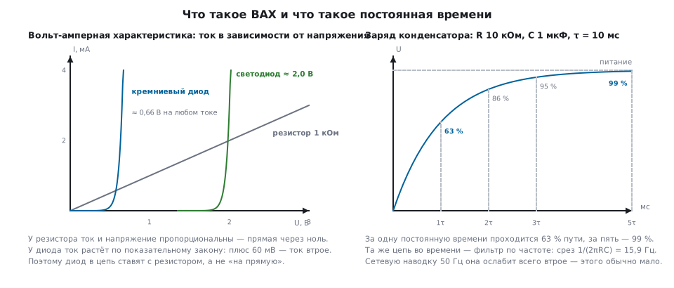
A diode is quite different. Its current grows exponentially: at 0.60 V 1.00 mA flows through a silicon diode, at 0.66 V already 3.62 mA. Plus sixty millivolts — three times the current. One decade of current takes about 107 mV, which is why reference books write "a drop of about 0.7 V": at any reasonable current it is almost the same.
Two practical consequences follow.
A diode or an LED is only switched on with a current limiter. If you apply a voltage slightly above the operating one to an LED, the current grows many times over and the part burns out. The resistor in the circuit (section 49.3) turns the task "set the voltage exactly" into the task "set the current approximately" — and that is achievable.
"Diode resistance" without an operating point is meaningless. At
0.66 V and 3.62 mA the static resistance U/I is 183 Ω, while
the differential one dU/dI is 12.9 Ω, fourteen times less. The first
answers the question "how much current at this voltage", the second "how
the current changes for a small change of voltage". In circuits with Zener diodes
and in regulators it is the second that matters.
50.2 The voltage divider
Two resistors between a voltage and ground; the signal is taken from the middle:
Uвых = Uвх · R2 / (R1 + R2)
A task that comes up all the time: measure a 12 V battery voltage with an ADC input whose full scale is 3.3 V. A 27 kΩ / 10 kΩ divider turns 12 V into 3.24 V — almost the whole scale. But 12 V is the nominal value: a lead-acid battery on charge sits at 14.4 V and more, and the same divider then gives 3.89 V — above the scale and above the supply. The ADC hits 4095, and an overshoot will open the input protection diode (section 62). So the divider is calculated for the highest voltage: 36 kΩ / 10 kΩ turn 15 V into 3.26 V, and 12 V into 2.61 V. The calculations below are for the 27/10 divider.
Current flows through the divider all the time: 12 V / 37 kΩ = 324 µA, that is 3.9 mW wasted. For a mains-powered device this is nothing; for a battery one it is sometimes more than a sleeping microcontroller consumes (section 46.5). The cure is either larger values or a switch that connects the divider only for the duration of the measurement.
A divider is not a voltage source. As soon as a load is connected to the output, it sits in parallel with the lower leg and the voltage drops:
| Load | At the output |
|---|---|
| none | 3.24 V |
| 1 MΩ | 3.22 V |
| 100 kΩ | 3.02 V |
| 10 kΩ | 1.88 V |
A load equal to the lower leg drops the output almost by half. For the sag to stay under one percent, the load must be larger than 723 kΩ — 72 times the lower leg.
The output impedance of the divider is R1 in parallel with R2, here 7.3 kΩ. This is the value that matters for the ADC: the input charges its internal capacitor through the source impedance, and the larger it is, the longer the sampling time has to be (section 14.2). Seven kilohms is acceptable with a sufficient sampling time; a hundred kilohms already needs attention.
50.3 The RC circuit in time
A resistor and a capacitor are the most common pair on a board. Their product
is called the time constant: τ = R · C. For 10 kΩ and 1 µF it is
10 ms.
A capacitor charges not linearly but exponentially:
| Elapsed | Charged to |
|---|---|
| τ | 63.2 % |
| 2τ | 86.5 % |
| 3τ | 95.0 % |
| 5τ | 99.3 % |
Hence the rule "five time constants and you can consider it charged": here that is 50 ms. The inverse problem is solved with a logarithm: the voltage reaches half in 6.93 ms — not half of 5τ, but noticeably sooner.
The same calculation is needed for start-up circuits, reset delays and the settling time of a reference voltage.
50.4 The RC circuit in frequency
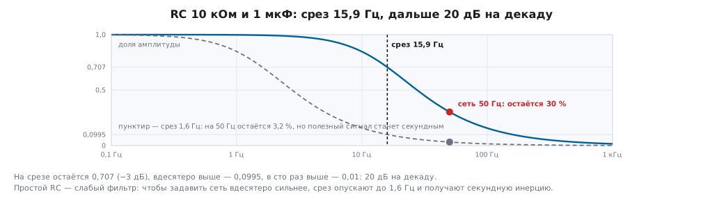
The same circuit is a low-pass filter. The cutoff frequency:
f = 1 / (2 · π · R · C)
For 10 kΩ and 1 µF it is 15.9 Hz; for 1 kΩ and 100 pF, 1.59 MHz.
At the cutoff frequency 0.707 of the amplitude remains (the familiar −3 dB); beyond it the attenuation goes at 20 dB per decade: ten times above the cutoff the amplitude is 0.0995, a hundred times above it is 0.01.
⚠️ A simple RC is a weak filter. 50 Hz mains interference through a filter with a 15.9 Hz cutoff is attenuated to 30 % — only threefold. To suppress it ten times more, you would have to lower the cutoff to 1.6 Hz, and that already means a lag of about a second. When you need it both fast and clean, use a filter of second or third order, or suppress the interference by averaging in software (for example, over a whole number of mains periods).
If you swap the resistor and the capacitor, you get a high-pass filter: the DC component does not pass, fast changes do. This is how AC coupling is done and how edges are caught.
50.5 🔧 PWM plus RC instead of a DAC
A classic trick: a PWM pin through an RC circuit gives an analog voltage proportional to the duty cycle (section 13.5). The average comes out exact, but a sawtooth remains on top of it.
With 1 kHz PWM through a 10 kΩ / 1 µF circuit (the period is a tenth of the time constant) and a duty cycle of 50 %:
- the average is exactly 1.650 V, as set;
- the ripple is 82.5 mV peak-to-peak, that is 2.5 % of full scale.
For LED brightness control this is invisible. For the reference voltage of a comparator or an ADC input it is not: 82 mV is a hundred steps of a 12-bit ADC.
The ripple can be reduced in two ways, and both cost something:
| What to do | Ripple | Price |
|---|---|---|
| before: τ = 10 ms | 82.5 mV | response 50 ms |
| τ = 100 ms | 8.2 mV | response 500 ms |
| raise the PWM frequency | proportionally | lower resolution (section 13.3) |
The rule: the ripple is proportional to the ratio of the PWM period to the time constant. Increasing τ, you pay in settling time — by exactly the same factor; raising the PWM frequency, you lose no time but pay in resolution: PWM at 10 kHz with the same 10 ms circuit gives the same 8.2 mV as τ = 100 ms, and still settles in 50 ms. If you need it clean, fast and at full resolution — you need a DAC (section 15).
50.6 A capacitor in front of the ADC
The second common case: a capacitor right at the ADC input. It is needed not so much for filtering as to supply the charge at the moment of sampling. The internal sample-and-hold capacitor has a capacitance of the order of a few picofarads; an external 100 nF is 20000 times larger.
When the input is connected, the charge is redistributed and the voltage sags by 50 parts per million — 165 µV at 3.3 V. The step of a 12-bit ADC is 806 µV, so the sag is five times smaller than one step and does not affect the result. Without the external capacitor all that charge would have to be drawn through the source impedance, and the sampling time would grow many times over.
But this holds only while the external capacitor manages to recharge through the source impedance between samples: for the divider from 50.2 the time constant is 7.3 kΩ × 100 nF = 0.73 ms. If samples are frequent and the sampling capacitor is discharged before each of them (the ADC scans channels, and the neighboring one sits near zero), the input draws an average current — sampling capacitance × voltage × sample rate. At 5 pF, 3.3 V and a million samples per second this is 16.5 µA, and across 7.3 kΩ the voltage sags by roughly 120 mV — a hundred and fifty steps. The input will not see fast changes of the signal behind such a circuit either. The external capacitor helps with infrequent measurements of a slow signal; for frequent ones you need a voltage follower (section 56.1).
50.7 Contact bounce
A mechanical contact does not close just once: it bounces several times, producing a burst of pulses hundreds of microseconds long. The microcontroller will see a dozen presses instead of one (section 7.6).
The hardware solution is an RC circuit at the input. If the capacitor sits right on the button (as in the schematic in section 8.5), it smooths only the rise of the voltage — the release and the bounces — but not the fall: the contact discharges it instantly, and any short touch or glitch is counted as a press at once. That is why a resistor is placed between the button and the capacitor. With a 10 kΩ resistor and a 100 nF capacitor, a press discharges the capacitor with a time constant of 1 ms, and the voltage takes 1204 µs to reach the low threshold of the input Schmitt trigger (about 0.3 of the supply). A release charges it through the pull-up and the same resistor, 20 kΩ, — 2408 µs to the high threshold (about 0.7 of the supply). Bounces of a hundred or two microseconds do not get through such a circuit, and a delay of a couple of milliseconds does not affect human perception.
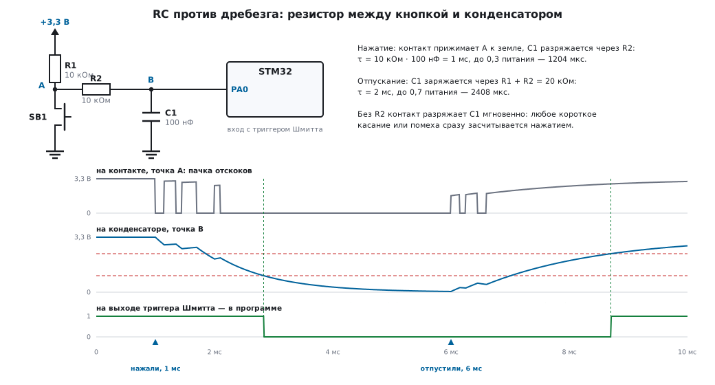
The software solution — a 20 ms delay before the state is confirmed — covers the same circuit with an eightfold margin even on release and needs no parts. People usually start with it, and use an RC where the input has to be clean in hardware: for example, when waking from sleep or at the input of a pulse counter (section 46.5).
50.8 Pitfalls
The voltage measured through a divider is lower than calculated. The load is comparable to the lower leg, or the ADC does not have time to take the charge: the output impedance of the divider is too high for the chosen sampling time.
Readings "drift" when switching ADC channels. A neighboring channel with a high source impedance did not manage to discharge the sampling capacitor. Increase the sampling time or put a capacitor on the input.
The divider drains the battery. 324 µA flow around the clock. Disconnect the divider with a switch.
The LED burned out "by itself". It was switched on without a resistor, or the voltage turned out slightly higher — with an exponential characteristic that is enough.
The filter does not suppress the interference. A single RC attenuates 50 Hz threefold, no more. Calculate with the formula, not "by eye".
The signal lags after an RC filter. This is not a defect but the price of filtering: the time constant works in both directions. In a control loop the lag eats the stability margin (section 47.2).
PWM through RC is "noisy" on the ADC. Ripple of 2.5 % of full scale. A larger time constant or a higher PWM frequency.
The button sometimes triggers twice. Bounce: there is neither an RC nor a software delay, or the capacitor sits right on the button, without a resistor.
50.9 Summary
- Linearity is a property of the resistor, not of parts in general; in a diode the current grows exponentially, and 60 mV change it threefold.
- Static and differential resistance are different quantities; in a diode they differ fourteen times.
- A divider is calculated with a formula but behaves as a source with an output impedance of R1 ∥ R2; a load comparable to a leg drops the output by half.
- The time constant
τ = RC: 63 % in τ, 99 % in 5τ; the inverse problem is solved with a logarithm. - In frequency the same circuit is a filter with cutoff
1/(2πRC)and a slope of 20 dB per decade; a single RC suppresses mains interference only threefold. - PWM through RC gives an exact average and a ripple of 2.5 % with a period of a tenth of the time constant. The ripple is proportional to the ratio of the period to τ: raising τ slows the response by the same factor, and raising the PWM frequency costs resolution.
- A capacitor at the ADC input is needed to supply charge at the moment of sampling.
- Bounce is suppressed by an RC with a resistor between the button and the capacitor (time constant 1 ms for a press and 2 ms for a release) or by a software delay of 20 ms.
Next: section 50а "Circuits in frequency: magnitude response, phase response and the Bode plot" — the same RC circuit across the whole frequency range: decibels, phase, second order, the filter in front of the ADC, and a frequency response measured by the microcontroller itself.