 Embedded HandbookApps
49. Voltage, current, power: Ohm's law and first calculations
A microcontroller does not work in a vacuum: around it there are resistors, LEDs, switches, regulators and connectors. An embedded programmer does not have to design power electronics, but must understand why an LED glows dimly, where the 4.7 kΩ in the schematic came from, and what happens if you hang eight LEDs on a pin instead of one.
Part VIII is about that electronics. It starts with three quantities from which everything else is built.
Terms used in the documentation
Term Meaning current, voltage, power the three basic electrical quantities direct / alternating current (DC / AC) current of constant / changing direction resistance, resistor opposition to current, and the part that provides it tolerance allowed spread of the nominal value power rating, derating allowed power, and its reduction as temperature rises forward voltage (Vf) voltage drop across a conducting diode pull-up / pull-down resistor resistor that ties a line to the supply / to ground E-series (E12, E24, E96) standard series of nominal values package, footprint component body, and its land pattern on the board trace, track copper conductor on a printed circuit board voltage drop voltage lost across an element sink / source current current flowing into / out of a pin
49.1 Three quantities
Current is the movement of charge through a cross-section of a conductor, measured in
amperes: I = Q / t. Voltage is the potential difference between two
points, in volts; it is what makes the charge move. Power
is the rate at which energy is transferred, in watts.
The water analogy is shaky, but it helps: voltage is the difference in height, current is liters per second, resistance is how narrow the pipe is, power is the work that the flow does.
The practical scale for embedded systems:
| Quantity | Typical use | Where you meet it |
|---|---|---|
| 3.3 V | logic supply | almost the whole board |
| 5 V | USB supply, sensors | regulator input |
| 1.8 V, 1.2 V | core, memory | inside the chip |
| 8 mA | pin current | LED, signal |
| 20 mA | pin limit | absolute maximum |
| 100 mA | all pins together | chip limit |
| 10…50 mA | current of the chip itself | depends on the frequency |
| µA | sleep mode | battery power |
49.2 Ohm's law and power
The three quantities are linked by one relation: U = I · R. You can rewrite it
any way you like: I = U / R, R = U / I.
Power, too, has three forms of the same thing:
P = U · I = I² · R = U² / R
Pick the one in which the quantities you need are known. It is useful to remember the orders of magnitude: at 3.3 V a 1 kΩ resistor passes 3.3 mA, 1 MΩ passes 3.3 µA, and 10 Ω passes 0.33 A (a pin can no longer deliver that much).
In series, resistances add up: two of 110 Ω give 220. In parallel, conductances add up: the same two give 55 Ω. From this follows a rule that saves time: resistances of very different values connected in parallel are determined by the smaller one — 100 Ω in parallel with 10 kΩ is 99 Ω.
49.3 🔧 A resistor for an LED
The task every board starts with: light an LED from a microcontroller pin.
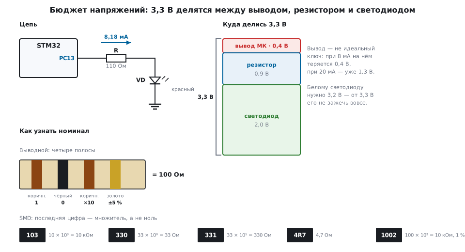
An LED is not a resistor: it has an almost fixed voltage drop, and the current is set by whatever is left. So you have to draw up a budget:
3,3 В = падение на выводе + напряжение на резисторе + напряжение на светодиоде
For a red LED at 8 mA: the drop on the pin is 0.4 V, on the LED 2.0 V, so the resistor gets 0.9 V.
R = (3,3 − 2,0 − 0,4) / 0,008 = 112,5 Ом
Nobody makes that value. The nearest one from the E24 series is 110 Ω, which gives 8.18 mA.
⚠️ The pin is what people forget most often. A microcontroller pin is not an ideal switch. At 8 mA it drops up to 0.4 V by itself, at 20 mA up to 1.3 V. Twenty milliamps through a pin means 26 mW dissipated inside the die — and that is not counting everything else.
What really sets the brightness. Not the resistor tolerance. The LED datasheet gives a typical and a maximum forward voltage — for the same red one, for example, 2.0 and 2.5 V. Calculating with the maximum is the worst case: the current drops from 8.18 to 3.64 mA, 2.25 times less (in practice the difference is smaller: at a lower current both the LED and the pin drop less). Between parts of one batch the spread is more modest — tenths of a volt, but even 0.1…0.2 V here reduce the current by 11…22 %, while a five-percent resistor tolerance changes it by only 5 % — down to 7.79 mA. The practical conclusion: if brightness matters, take LEDs from one batch or use a current source instead of a resistor.
A white LED will not reach full current from 3.3 V. At its operating current it needs 3.0…3.4 V — nothing is left for the resistor and the pin. At a current of a milliamp or two the forward voltage is lower, and as an indicator it does light from 3.3 V, but then the current is set not by the resistor but by the spread of the forward voltage and by the supply. For full brightness you need a boost converter, a 5 V supply or a driver.
49.4 Not every value exists
Resistors are made in series: E6, E12, E24, E48, E96, E192 — the number is how many values fall into one decade. The E24 series has twenty-four values from 1.0 to 9.1; after that everything repeats with a multiplier of 10.
| Series | Values per decade | Step | Usual tolerance |
|---|---|---|---|
| E12 | 12 | 21 % | 10 % |
| E24 | 24 | 10.1 % | 5 % |
| E96 | 96 | 2.4 % | 1 % |
The series step is roughly twice the tolerance — so that the ranges of neighboring values almost meet. "Almost": of the 23 pairs of neighbors in E24, 16 overlap, and the rest leave a gap of up to 4.4 %. This has no practical significance — but it explains why the series look "oddly" chosen.
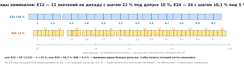
Common values worth keeping in the drawer: 10, 22, 47, 100, 220, 330, 470, 1k, 2.2k, 4.7k, 10k, 22k, 47k, 100k, 1M.
49.5 Markings
Through-hole parts — with colored bands. The first two (or three) are digits, the next is the multiplier, the last is the tolerance.
| Color | Digit | Color | Digit | |
|---|---|---|---|---|
| black | 0 | green | 5 | |
| brown | 1 | blue | 6 | |
| red | 2 | violet | 7 | |
| orange | 3 | gray | 8 | |
| yellow | 4 | white | 9 |
Brown-black-brown-gold = 10 × 10¹ = 100 Ω ±5 %. Yellow-violet-red = 47 × 10² = 4.7 kΩ — the most common pull-up in the world.
SMD — with digits. Three digits: two significant ones and a multiplier.
| Code | Value | |
|---|---|---|
103 |
10 × 10³ = 10 kΩ | |
330 |
33 × 10⁰ = 33 Ω | not 330! |
331 |
33 × 10¹ = 330 Ω | |
4R7 |
4.7 Ω | the letter stands in place of the decimal point |
1002 |
100 × 10² = 10 kΩ | four digits — 1 % accuracy |
000 or 0 |
jumper | 0 Ω, used instead of a wire |
⚠️
330means 33 Ω. The last digit is always the multiplier, even when it looks like a zero of the value. The mistake costs ten times the current.
Capacitors are marked the same way, but the result is in picofarads: 104 =
10 × 10⁴ pF = 100 nF (the very decoupling capacitor at every supply pin), 225 =
2.2 µF. The smallest packages are often not marked at all — then only the
reel knows the value, and spilling a tape of capacitors means
losing them.
49.6 Power and package
A resistor dissipates P = I²R as heat, and the package has to get rid of that
heat.
| Size code | Size, mm | Power rating |
|---|---|---|
| 0402 | 1.0 × 0.5 | 62.5 mW |
| 0603 | 1.6 × 0.8 | 100 mW |
| 0805 | 2.0 × 1.25 | 125 mW |
| 1206 | 3.2 × 1.6 | 250 mW |
| 2512 | 6.4 × 3.2 | 1 W |
In the LED circuit the resistor dissipates 7.4 mW — any package will do. A 4.7 kΩ pull-up at 3.3 V draws 702 µA and 2.3 mW while the input is held at ground. But a current-sense shunt (section 44.8) at 10 A dissipates a whole watt — and there you already need a 2512 or a special package.
An important caveat: the rated power applies at room temperature. As it heats up, the rating has to be reduced; in a tight box without ventilation, take a twofold margin.
49.7 What a microcontroller pin can do
Numbers worth knowing by heart (G4 family; the others are similar):
| Limit | Value |
|---|---|
| current of one pin | 20 mA (absolute maximum) |
| normal operation | ±8 mA with guaranteed levels |
| all pins together | 100 mA |
| through the supply pins | 150 mA |
| drop on a pin at 8 mA | 0.4 V |
| drop at 20 mA | 1.3 V |
From this follows the practice: LEDs at 8.18 mA each fit on one chip twelve at most — and that is already the whole budget, you cannot drive anything else. Eight leaves a margin. More than that needs multiplexed driving, shift registers or a driver.
"Absolute maximum" means not an operating mode but the boundary beyond which damage begins. Design with a margin: if the datasheet says 20 mA, the operating point is 8–10.
49.8 Wires and traces have resistance too
Copper conducts well, but not perfectly. A trace 100 mm long and 0.25 mm wide on a board with standard copper thickness has 200 mΩ. At a current of 1 A that is 0.2 V of loss and 0.2 W heating the trace itself.
Width scales linearly: the same trace 2 mm wide is only 25 mΩ, eight times less. Hence the layout rules: power nets as wide pours, ground as a solid layer, and never route measurement nets through power traces (the drop across them ends up in the measurement).
The same effect applies to wires: two meters of thin wire to a sensor are tenths of an ohm, and when you measure the resistance of a thermometer they turn into degrees.
49.9 Pitfalls
The LED is dim or does not light. The drop on the pin was not taken into account;
3.3 V is enough for a white LED only at a weak current; the resistor turned out
ten times
larger because of the marking 331 instead of 330.
LEDs of different brightness. Spread of forward voltage between parts: in the worst case per the datasheet — up to 2.25 times in current, within a batch — 10–20 %. One batch, or a current source.
The microcontroller heats up, pins "sag". The total current of the pins is close to 100 mA. Count the budget over all pins at once.
The resistor has darkened. The power exceeded the rating for the package.
Recalculate I²R and take a size code with margin.
The circuit works on the bench but not on the board. Drop on long thin traces, or a ground shared with a power circuit.
The pull-up "does not pull up". Too large a value in the presence of noise, or too small with battery power — 4.7 kΩ is a compromise, not a dogma: for slow lines take 10…100 kΩ, for fast ones 1…2.2 kΩ.
Bought 100 Ω, got 100 kΩ. The multiplier band was confused with the tolerance band: read from the end with the narrower gap, or, simpler, measure it.
49.10 Summary
U = I · R,P = U · I = I²R = U²/R— from these two formulas you derive almost everything needed on the board around a microcontroller.- An LED is calculated as a voltage budget, including the drop on the pin: 0.4 V at 8 mA, 1.3 V at 20 mA.
- The spread of an LED's forward voltage affects the current more than the resistor tolerance: in the worst case per the datasheet — 2.25 times, within a batch — 10–20 %, against five percent for the resistor.
- Values come in series: E24 with a 10 % step and 5 % tolerance covers almost everything, E96 is for where you need accuracy.
- The last digit of an SMD marking is always the multiplier:
330= 33 Ω. - Choose the size code by the dissipated power, with a margin for heating.
- One pin — up to 20 mA, all together — up to 100 mA; design for 8–10.
- Traces and wires have resistance: 100 mm × 0.25 mm = 200 mΩ.
Next: section 50 "I-V curves, voltage divider, RC circuits" — how elements whose resistance is not constant behave, and what happens when time enters the circuit.