 Embedded HandbookApps
36д. Oscilloscope, part 2: triggering — every kind of trigger and when to use which
A digital oscilloscope records its input all the time, but shows only a piece around one instant — the trigger point. The trigger condition decides which piece you see: an ordinary period of the signal, a rare fault, or exactly the byte on the bus after which everything went wrong. Section 36а.4 covers the basics: source, edge, level, and the auto, normal and single modes. This section covers the rest: every kind of trigger and every one of its settings. For each — what it is, what it is for, what you see with it and without it, a typical mistake and a case from board debugging.
The main idea of the section: a smart trigger replaces waiting at the screen. Between records the instrument is blind most of the time (36г.17), and a rare event caught "by edge" slips past. A condition that is true only during the fault fires on every fault — even if it happens once an hour.
The examples use the author's instrument, the RIGOL DHO900: menu items are given in English as on the screen, numbers come from its documents. Most digital oscilloscopes have the same kinds of trigger; what applies only to the DHO900 is marked as such.
Sources: DHO900 User Guide (Books/DHO900_UserGuide_EN.pdf; page numbers
here and below are PDF file pages): p. 37 — trigger keys and knob, p. 77 —
source, p. 78 — level, pp. 79–80 — modes and Force, p. 80 — coupling,
p. 81 — Holdoff and Noise Reject, pp. 82–126 — seventeen trigger types,
p. 127 — AUX OUT output, p. 178 — digital channel threshold; RIGOL DHO900
Datasheet (Books/dho900-datasheet.pdf): p. 9 — logic probe,
p. 11 — digital channels and pre-trigger record, p. 12 — digital channels
in time, pp. 13–15 — trigger system, p. 23 — AUX OUT; section 17.3 —
the I²C bus edge. All
calculated numbers come from a run of _verify/trig36d/model36d.py (Python 3.11 and
numpy in the stm-lab:1 container).
What it is called in the documentation
Original Meaning trigger, trigger event; arm the trigger, the trigger event; arming (ready to catch) pre-trigger / post-trigger buffer memory before / after the trigger point sweep: Auto, Normal, Single; Force sweep mode: automatic, waiting, one-shot; forced trigger trigger level, threshold; 50% trigger level, threshold; level set to the middle of the swing trigger sensitivity, hysteresis trigger sensitivity, hysteresis: how far the signal must come back before the trigger re-arms Noise Reject noise suppression in the trigger path trigger coupling: DC, AC, LFR, HFR trigger coupling: direct, through a capacitor, low-frequency reject, high-frequency reject holdoff delay before the next trigger is accepted Edge, Pulse, Slope, Video edge, pulse width, rise or fall time, video Pattern, Duration logic pattern, pattern duration Timeout, Runt, Window (Over) timeout, a pulse that does not reach full level (runt), window Delay, Setup/Hold, Nth Edge delay between edges of two signals, setup and hold, Nth edge RS232, I2C, SPI, CAN, LIN trigger on bus content AUX OUT, TrigOut trigger output on the rear panel
36д.1 What the trigger does: memory before and after, arming
What it is. During a record the memory is split into two parts: before the trigger point and after it. How the DHO900 does it (User Guide p. 79): after you press RUN or SINGLE, the instrument first fills the pre-trigger part and only then starts looking for the condition. While it looks, new points push out old ones — the memory always holds the last moments before the event. When it finds the event, it fills the part after it and draws.
Why you need to know this. The pre-trigger part is set by the position of the trigger point on the screen (36г.10); on the DHO900 — up to 5 divisions. On a fast time base that is nanoseconds, on a slow one — seconds: at 100 ms/div the instrument is blind for 0.5 s after SINGLE, at 1 s/div — 5.0 s.
What you see. You press SINGLE and power up the board at once — the supply ramp is not caught, the instrument keeps waiting. Power it up a couple of seconds later — it is caught, and on the left you see what came before.
Mistake. Assuming the instrument is "ready" the moment you press the key. On a slow time base, wait until the pre-trigger part is filled, or move the trigger point to the left edge (36г.10).
DHO900 controls (User Guide p. 37). The trigger menu key, the slope key (works only for the Edge type), the FORCE key and the LEVEL knob: turning it moves the level, pressing it sets the level to the middle of the swing. The trigger label at the top of the screen shows the type, source, level and mode: A, N or S (p. 79).
36д.2 Sweep modes: Auto, Normal, Single and Force
What it is. The Sweep item (User Guide pp. 79–80; datasheet p. 13):
- Auto (default) — if the condition is not met for a while, the instrument triggers by itself and draws what is there;
- Normal — draws only on the condition; no event — the last record stays on the screen;
- Single — waits for one event, records it and stops (STOP); you can zoom and pan the record — new ones will not overwrite it.
Why Auto. When the signal level is unknown, when the signal is constant (a supply rail, a reference voltage) and when you need to see anything at all before setting up the trigger. In Normal a constant voltage gives no events — the screen is empty, and the instrument seems frozen.
Why Normal. A rare signal. A sensor is polled 4 times per second, a packet on the bus comes once every 250 ms. How long Auto waits before triggering by itself is not in the DHO900 documents; the model uses a nominal 40 ms. Then every real record comes with 6 forced triggers: 85.7 % of frames are a line without the packet, and the picture flickers. Normal shows the packet and keeps it on the screen until the next one.
Force. In Normal and Single the FORCE key (or Force in the menu) makes one trigger without the condition. Why: to check that the signal exists at all and where it is on the screen, without changing settings.
Mistake. Pressing FORCE in Single "just to check" — the instrument records a random piece and stops, and the event you were waiting for slips past. The reverse: hunting a rare fault in Auto — forced triggers fill the screen with empty frames, and with persistence (36г.18) the fault drowns in them.
Case. The board resets once every few hours. A channel on the NRST reset pin, falling-edge trigger, Normal, and once set up — Single. In the morning the screen shows the reset pulse and, on the left, what came before it (36д.1).
36д.3 Level, sensitivity and Noise Reject
What it is. The level (Level) is the voltage whose crossing fires the condition. The LEVEL knob, the Level field or the 50% button (User Guide p. 78). The level line is visible while you turn it and disappears after 2 s. On the DHO900 the level can be set within ±4.5 divisions of the screen centre (datasheet p. 13): at 500 mV/div that is ±2.25 V. A signal off the screen is also a signal you cannot trigger on.
Hysteresis. A plain "above the level — below the level" comparison fires many times on a noisy edge: noise throws the signal across the level back and forth. So the trigger circuit re-arms only after the signal has moved away from the level by some amount — that is hysteresis. The DHO900 datasheet does not name it, but it names a related parameter — sensitivity: 0.5 division (on scales from 50 mV/div), 0.7 division with Noise Reject on (datasheet p. 13). The model takes the hysteresis equal to the sensitivity — this is an assumption.
Model: an edge 0…3.3 V in 10 µs (slope 0.33 V/µs), noise 60 mV (peak-to-peak about 360 mV), level 1.65 V, scale 500 mV/div; 200 runs.
| hysteresis | rising triggers per edge | false "falling" on the same edge |
|---|---|---|
| none | 35.9 | 34.9 |
| 0.5 division — 250 mV | 1.3 | 0.4 |
| 0.7 division — 350 mV (Noise Reject) | 1.0 | 0.0 |
What you see. Without hysteresis a "falling" trigger fires on a rising edge, and a pulse width trigger (36д.8) catches nanosecond noise spikes. With 250 mV of hysteresis the 360 mV noise still gets through — an occasional double trigger; with 350 mV — one trigger per edge. The trigger point still wanders: a spread of 102 ns (one standard deviation), and the flatter the edge, the larger it is.
Noise Reject (a switch in the menu, User Guide p. 81) — suppression of high-frequency noise in the trigger path; the datasheet adds that it increases the delay of the trigger circuit. All DHO900 trigger types have it.
Mistake. Setting the level right at the flat top of the signal, where ringing and noise live (36а.4), — or on a gentle slope, where noise shifts the trigger point the most. Put the level in the middle of the steepest part.
36д.4 Trigger coupling: DC, AC, LFR, HFR
What it is. A filter between the channel and the trigger circuit. It changes only what the trigger circuit sees — the picture on the screen stays as it was; do not confuse it with channel input coupling (36г.5). On the DHO900 the Coupling item exists only for the Edge trigger and only for an analog channel (User Guide p. 80), default DC:
- DC — the whole signal;
- AC — without the DC part;
- LFR — without the DC part and low frequencies;
- HFR — without high frequencies.
The LFR and HFR cut-off on the DHO900 is 120 kHz (datasheet p. 13). The time constant of such a single-pole filter is 1.33 µs.
HFR: triggering on a noisy line. A 10 kHz PWM with 2 MHz noise from a DC-DC converter on it. After HFR, 99.7 % of the PWM and 6.0 % of the noise remain: the trigger stops firing on spikes. The price is delay: after the filter the edge crosses the middle 0.92 µs later (the step model — also 0.92 µs). At 100 ns/div that is 9.2 divisions — the real edge goes off the left edge of the screen. And a 1 MHz SPI clock after HFR keeps 11.9 % of its amplitude: there may be no trigger at all.
LFR: triggering on a signal with pickup. A long wire picks up 50 Hz mains, and the level of a digital signal "floats": the edge trigger comes and goes. After LFR, 0.042 % of the 50 Hz pickup remains, while a 1 MHz clock passes at 99.3 %. Mistake: LFR on a slow signal — a 1 kHz square wave passes at 0.83 %, and there is no trigger.
AC: level relative to the average. A signal whose DC part drifts (a battery discharging, a sensor warming up) — the trigger level stays in the middle of the swing. The AC cut-off is not in the DHO900 documents. Mistake: AC on a PWM with a small duty cycle — for the trigger circuit a 10 % PWM lies between −0.33 and 2.97 V (like the channel AC coupling in 36г.5), and the level "1.65 V" is not where it seems. On the DHO900, with AC and LFR the level line is not drawn on the screen — only the number in the label (User Guide p. 80).
36д.5 Trigger holdoff (Holdoff)
What it is. After each trigger the trigger circuit accepts no new events for a set time. On the DHO900 — from 8 ns (default) to 10 s (User Guide p. 81; datasheet p. 13).
Why. A signal made of bursts: SPI clocks, UART bytes, stepper driver pulses. Every edge in the burst meets the condition "rising edge", and the instrument, arming at a random moment, catches the first one that comes. Records start on different clocks — and the picture jumps.
Model: SPI at 8 MHz, 8 clocks of 125 ns, a byte every 2 µs; from the first edge of the burst to the last t1 = 875 ns, the pause before the next byte — 1125 ns, the burst period t2 = 2 µs. Arming happens at a random moment (the dead time between records is much longer than the period, 36г.17); 20000 records.
| Holdoff | different trigger positions | trigger on the 1st clock |
|---|---|---|
| 8 ns (default) | 8 | 56.2 % (calculation 56.25 %, the others 6.25 % each) |
| 500 ns — less than t1 | 3 | 71.7 % |
| 1.5 µs — between t1 and t2 | 1 | 100.0 % |
| 2.6 µs — more than t2 | 2 | 56.6 % |
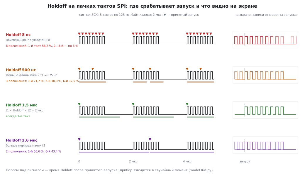
With and without holdoff. Without it the instrument catches the first clock in only 56.2 % of records — the share of the pause in the period; in the rest — any of the next seven, and the screen shows eight overlaid shifted copies. A holdoff longer than the burst but shorter than the period discards all clocks except the first: one position, the picture stands still. Exactly this rule is given in the User Guide: greater than t1, less than t2.
Mistake — missing on either side. Shorter than the burst (500 ns): after the first clock the holdoff ends in the middle of the burst, and the trigger lands on the 5th or 6th clock — three positions. Longer than the period (2.6 µs): the holdoff steps over the next byte and ends inside it — a trigger every other byte, on the 1st or the 6th clock. Tune Holdoff by watching the picture: increase it until the picture stands still.
Important. In the model the holdoff counter runs continuously — that is how it stabilises bursts even when the instrument arms rarely. How it is built inside the DHO900 is not said in the documents. The Edge, Pulse, Slope, Pattern, Duration, Runt, Window, Delay and Setup/Hold types have Holdoff; Video, Timeout, Nth Edge and the bus triggers do not (User Guide, pp. 82–126) — they do not need it: the condition itself picks one place.
36д.6 Source: analog and digital channels, no external input
Analog channels. CH1–CH4 (User Guide p. 77). A DHO900 feature: the trigger works on a channel even if it is switched off — the signal is not shown, but the condition is checked.
Digital channels. D0–D15 — only with the PLA2216 logic probe connected (bought separately; datasheet p. 9). The threshold is set for the D0–D7 group and separately for D8–D15 (User Guide p. 178; the LEVEL knob also changes it, p. 78). Preset thresholds: TTL 1.4 V, CMOS5.0 2.5 V, CMOS3.3 1.65 V, CMOS2.5 1.25 V, CMOS1.8 0.9 V and others; threshold accuracy is ±(100 mV + 3 % of the threshold), and the shortest detectable pulse is 5 ns (datasheet pp. 11–12).
Mistake — the threshold does not match the logic. A 1.8 V bus, with the threshold left at CMOS3.3: 1.65 V ± 149.5 mV — from 1.500 to 1.799 V. The margin to the logic one level is 0.5 mV: the instrument reads some ones as zeros, and the trigger disappears. CMOS1.8 (0.9 V ± 127.0 mV, from 0.773 to 1.027 V) puts the threshold in the middle of the swing. For 3.3 V, TTL also works: from 1.258 to 1.542 V.
The DHO900 has no external trigger input. The sources are only CH1–CH4 and D0–D15 (User Guide p. 77, datasheet p. 13); other instruments may have EXT (a separate input used only for triggering) and a mains trigger (AC Line). If you need a "fifth" signal only for triggering, bring it to a digital channel.
There is a trigger output. The [AUX OUT] connector on the rear panel: in the Utility menu, Aux Out item — TrigOut (User Guide p. 127). One pulse per trigger: the high level is at least 2.5 V open circuit and at least 1.0 V into 50 Ω (datasheet p. 23). Why: to trigger a second instrument (a logic analyzer, a second oscilloscope) from the same event. And to measure the frequency of these pulses with a counter — it is exactly the update rate of the instrument at the current settings, that is, its dead time (36г.17).
36д.7 Edge (Edge)
What it is. The simplest trigger: crossing the level upwards (Rising), downwards (Falling) or in either direction (Either) (User Guide pp. 82–83). The basics are in 36а.4; here is what is not there.
Why Either. To see both edges of a signal on one screen: for example, the jitter of both the rise and the fall of a marker pin (36а.7), or to catch the first transition of a line whose polarity is unknown in advance.
Mistake. Either on a clock signal: records start on a rise or on a fall — the screen shows a straight and an inverted square wave overlaid. And Edge as a tool for catching a fault: an edge trigger fires on every normal edge, and the fault shows up only if it falls inside the record. For faults — the types in 36д.8–36д.15.
36д.8 Pulse width (Pulse)
What it is. A trigger on a pulse of a given duration: positive or negative (Polarity), longer (>), shorter (<) or within (< >) the set value (User Guide pp. 83–86). Limits are from 1 ns to 10 s. The width is measured between the two crossings of the trigger level.
Why. To catch a pulse that must not be there. UART at 115200 baud: a bit lasts 8.68 µs, and nothing on the line should be shorter than a bit. The condition "positive, < 4.34 µs" (half a bit) stays silent on any data and fires on a noise spike. The reverse "> X" catches a PWM whose duty cycle went past its limit, or a "break" — the line held low longer than a frame.
What you see with it and without it. On edge, the record fires on every bit, and a 300 ns spike reaches the screen only if it happened inside the recorded window. On width — records only with the spike, no matter how many normal bytes passed between them.
Mistake — the width depends on the level. A pulse of 1 µs at half swing with 200 ns edges: at the 10 % level it lasts 1.16 µs, at 50 % — 1.00 µs, at 90 % — 0.84 µs. The condition "> 1.1 µs" at the 10 % level fires on every normal pulse, at 50 % — on none. Put the level at 50 %, and the limit with a margin from normal.
The trigger fires when the width is already known — on the trailing edge of the pulse; the pulse itself is on the screen to the left of the trigger point. Shift the trigger position (36г.10) to leave room on the left.
36д.9 Rise time (Slope)
What it is. A trigger on the time an edge takes to pass between two levels: A (upper) and B (lower). Edge Rising or Falling, condition >, < or < >, limits from 1 ns to 10 s; source — CH1–CH4 only (User Guide pp. 86–89). The Linkage tick moves both levels together; pressing the LEVEL knob switches which level it adjusts.
Why. A slow edge is a sign of a weak pull-up, an overloaded output, a large line capacitance. The I²C bus: in 17.3 the rise time limits between 30 and 70 % are 1000 ns in standard mode and 300 ns in fast mode. Model of an RC edge at 3.3 V (levels A = 2.31 V and B = 0.99 V):
| pull-up | line capacitance | rise time |
|---|---|---|
| 4.7 kΩ | 100 pF | 398 ns |
| 2.2 kΩ | 100 pF | 186 ns |
| 4.7 kΩ | 400 pF | 1593 ns |
The condition "Rising, > 300 ns" fires on every edge with a 4.7 kΩ pull-up — the bus is not fit for 400 kHz, although "by eye" the edges look alike.
Mistake. Levels A and B outside the signal swing — the edge does not pass both, and there is never a trigger. Or they are left at 90 % and 10 % (the menu buttons set exactly these, User Guide p. 78), while the limit comes from a document where time is measured between 30 and 70 % — the numbers are not comparable.
36д.10 Video (Video)
What it is. A trigger on the sync pulses of a video signal: NTSC, PAL/SECAM and formats from 480p to 1080i (User Guide pp. 89–91; datasheet p. 14). The Sync item: All Lines — any line, Line — a line by number (for PAL — from 1 to 625), Odd and Even — the odd and even field (NTSC and PAL/SECAM only); Polarity — the sync pulse polarity.
Why. A microcontroller generating composite video, a camera module with an analog output, a video capture board. In PAL a line lasts 64 µs, a field — 20 ms.
With it and without it. On edge, the instrument triggers on a line sync pulse, then on a frame sync pulse, then on a bright spot in a line — the picture does not stand still. On Line 100 — always the same line, and you see its content.
Mistake. Wrong standard or polarity — no trigger. And shallow memory: the User Guide advises a larger memory depth for video (p. 91) — a 64 µs line on 10k points comes out coarse (36г.14).
36д.11 Logic pattern (Pattern)
What it is. A trigger on a combination of levels on several channels: each gets 1 (above its level), 0 (below) or X (don't care), and one gets an edge (User Guide pp. 91–94). Sources — CH1–CH4 and D0–D15. If an edge is set, the trigger is on that edge while the pattern holds on the others; if not — on the edge after which the pattern became true. All X — no trigger; the instrument will not accept a second edge in the pattern ("Invalid input").
Why. An event defined by several lines at once: an SPI display clock while CS = 0 and DC = 1 (data, not a command); a state machine state put out on three debug pins (code 101 — the branch you need).
Mistake — a false pattern during switching. Two lines change "together" but arrive with skew: on the DHO900 digital channels it is up to ±5 ns (datasheet p. 12). Model: out of 10000 simultaneous switchings, 96 % briefly (up to 5.0 ns) show an intermediate pattern — and if it matches the set one, the trigger is false. The cure is pattern duration (36д.12): the condition "> 20 ns" let none of them through (0 %).
36д.12 Pattern duration (Duration)
What it is. The same 1/0/X pattern (without edges), but the trigger fires when it holds longer (>), shorter (<), within (< >) or outside (> <) the set time (User Guide pp. 94–97). Limits are from 1 ns to 10 s.
Why. CS stays low longer than a normal transfer — an interrupt cut into the middle of an SPI transaction or DMA got stuck. Two buttons held together longer than a threshold. The I²C bus: both lines low longer than ever happens in normal operation — someone is holding the bus.
Difference from Pulse. Pulse is the width of a pulse on one channel. Duration is the time a combination of several channels holds.
Mistake. A channel that does not matter is left at 1 or 0 by default instead of X — the pattern never matches.
36д.13 Timeout (Timeout)
What it is. A trigger when the signal, after crossing the level (Rising, Falling or Either), takes too long to cross it again (User Guide pp. 97–99). The trigger fires at the moment the time runs out — without waiting for the next edge.
Why. The "heartbeat" of the program: the main loop toggles a pin once per 1 ms. Model: 3000 toggles with ±10 % spread, the longest normal gap — 1.10 ms; once the loop hung, and the gap was 41.0 ms. A 1.5 ms timeout fired 1 time — exactly on the hang.
Difference from Pulse ">". A width trigger will also catch this gap, but only when the line toggles again — 41.0 ms later. At 1 ms/div you see 5 ms to the left of the trigger: the last normal edge and everything before the hang are already off the edge. The timeout fires 1.5 ms after the last edge — and it is on the screen. And if the program hung for good, there will be no next edge, and Pulse will never fire.
More cases. SCL of the I²C bus low longer than reasonable — a slave stretched the clock and did not let go; a UART line silent longer than the pause between packets; a watchdog not refreshed in time (36в).
Mistake. A timeout shorter than the longest normal gap — a trigger on every slow pass of the loop. First look at the normal spread (persistence, 36г.18), then set the limit.
36д.14 Runt pulse (Runt)
What it is. A pulse that crossed one level but did not reach the other: a "runt" (User Guide pp. 99–101; source — CH1–CH4). For a positive one — it rose above the lower level B and fell back without reaching the upper level A. In addition — a condition on its width: None, >, <, < >.
Why. A logic level that became neither a zero nor a one: two chips pull the line in opposite directions at the same time, an output cannot keep up with a pulse that is too short, a level shifter is at its limit. A receiver may read such a pulse any way at all — this is the "floating" fault.
With it and without it. Model: 1000 pulses of 3.3 V, one reached only 1.2 V. An edge trigger at 1.65 V fires 999 times — the runt is below the level and is never seen. An edge at 1.0 V — 1000 times: the runt is among them, but that is 0.1 % of records, impossible to find by eye. Runt with levels A = 2.5 V and B = 0.8 V — 1 time, exactly on it.
Mistake. Levels A and B too close to the flat tops: noise on the top itself crosses B and does not reach A — a trigger on noise. Put the levels inside the swing with a margin above the noise (36д.3).
36д.15 Window (Window)
What it is. Two levels — upper and lower; the trigger fires when the signal leaves the band (Exit), enters it (Enter) or has stayed in it for a set time (Time, from 1 ns to 10 s) (User Guide pp. 102–103; source — CH1–CH4). In the Type list the User Guide calls this type "Over".
Why. Power. A 3.3 V rail, a band of 3.0…3.6 V: one condition catches both a dip and a spike — no need to guess which way the fault goes.
With it and without it. Model: a 3.3 V rail with noise, a 0.4 V dip and a 0.35 V spike. A falling trigger at 3.0 V fired 1 time — only on the dip; a rising trigger at 3.6 V — 1 time, only on the spike. Window Exit — 2 times: both events with one condition.
Mistake — the band does not fit. Trigger levels must be within ±4.5 divisions of the centre (36д.3). The screen centre is moved to 3.3 V with offset (36г.4); at 100 mV/div the limit is ±0.450 V — a ±0.3 V band fits; at 50 mV/div the limit is ±0.225 V — it no longer does. And a band that is too narrow: noise alone leaves it, and the trigger fires continuously.
36д.16 Delay between two signals (Delay)
What it is. Two sources: edge A and the neighbouring edge B; the trigger fires when the time between them is greater (>), less (<), within (< >) or outside (> <) the set value (User Guide pp. 104–106). Sources — CH1–CH4 and D0–D15.
Why. Firmware response time. A is an interrupt input (a button, a sensor ready signal), B is the pin that the handler toggles first thing. Model with nominal numbers: the response is usually 1.2 µs, but now and then interrupts are disabled for long (a flash write, a long critical section), and the response takes up to 30.0 µs. Out of 10000 events there are 35 such; the condition "> 5 µs" catches only them.
With it and without it. On edge A you see 10000 normal responses, and a slow one reaches the screen by chance. On Delay — only slow ones, and to the left of them you see what the processor was busy with, if you put that out on other channels.
Mistake. Edges A and B are not neighbours: another edge A manages to pass between them — the instrument measures the wrong pair. And A and B swapped: the condition is never true.
36д.17 Setup and hold (Setup/Hold)
What it is. A clock (SCL in the menu) and data (SDA): setup time — how long the data is stable before the clock edge, hold time — how long after. The trigger fires if one of them (or either — the Setup/Hold item) is less than the set value (User Guide pp. 106–109). Data Type — which data level to check: H or L.
Why. An SPI slave reads a bit on a clock edge. If the master is set to a different mode (CPHA, 18.2), the data changes on the same edge on which it is read. Model: a 1 MHz clock, data changes a nominal 10 ns after the edge.
| modes | setup | hold |
|---|---|---|
| match: data changes on the falling edge | 500 ns | 500 ns |
| do not match: on the same edge | 990 ns | 10 ns |
The condition "hold < 50 ns" stays silent with the correct setting and fires on every bit with the wrong one. From the outside the bits "almost read": the slave catches either the old bit or the new one, depending on temperature and wire length.
Mistake. Swapping SCL and SDA in the menu — the instrument measures the time from data to data. The DHO900 menu names are the same as for I²C, but this trigger is not about I²C — it is about any "clock + data" pair.
36д.18 Nth edge (Nth Edge)
What it is. A trigger on the Nth edge after a pause (Idle Time) (User Guide pp. 109–111). N is from 1 to 65535. The pause must be longer than the largest gap between the counted edges and shorter than the pause before the burst.
Why. I²C at 100 kHz: the SCL clock is 10 µs; the address and the R/W bit take 8 clocks, the 9th is the acknowledge (ACK) clock. Between transactions SCL stays idle longer, for example milliseconds. A pause of 50 µs and N = 9 — a trigger on the ACK clock of the first byte: you see at once whether the slave answered, with no decoding needed (36ж).
With it and without it. On an SCL edge — a trigger on any of the clocks, and the picture jumps as without Holdoff (36д.5). Here Holdoff is not needed — the count itself picks one place.
Mistake. A pause shorter than the gap between clocks inside the burst — the count resets in the middle of a byte. The slave stretches the clock (clock stretching) — the gap inside the transaction grows, and the pause must be longer than that too.
36д.19 Bus triggers: RS232, I2C, SPI, CAN, LIN
What it is. The instrument decodes the bits itself and triggers on content — not on an edge, but on a byte, an address, an error. How to show the decoded data and search the record — part 4 (36ж). What the DHO900 catches (User Guide pp. 111–126; datasheet p. 15):
| bus | trigger conditions | settings |
|---|---|---|
| RS232 (UART) | Start, Error, Check Error, Data | Polarity, Baud Rate, Data Bits 5–8, Stop Bit 1/1.5/2, Parity None/Even/Odd |
| I2C | Start, Stop, Restart, MissedAck, Address, Data, A&D | SCL, SDA, AddrBits 7/8/10, Direction, Bytes 1–5 |
| SPI | data after CS or after a clock pause (Timeout) | CLK, MISO, CS, Slope, DataBits 4–32, Timeout from 8 ns to 10 s |
| CAN | SOF, EOF, Remote ID, Overload, Frame ID, Frame Data, Data&ID, errors | Signal Type CAN_H/CAN_L/TX/RX/DIFF, Baud, Sample Position 10–90 %, Bytes 1–8 |
| LIN | Sync, ID, Data, Data&ID, Sleep, Wakeup, Error | Version 1.X/2.X/Both, Baud, Sample Position, Bytes 1–8 |
UART on the DHO900 — up to 20 Mb/s, CAN — up to 5 Mb/s (datasheet p. 15).
UART: baud rate and polarity. The instrument counts bits from the start bit at the set rate. With a rate mismatch the error builds up towards the end of the frame: to the middle of the stop bit — 9.5 bits. A 3 % mismatch shifts the read point by 28.5 % of a bit — the frame reads; 6 % — by 57.0 %, past the middle of the bit: the instrument sees a framing error where there is none. The limit is 5.26 %. Error is useful on its own: a trigger on a framing error catches a baud rate fault on the board. Polarity: on an RS-232 line after the level converter the logic is inverted relative to the UART on the microcontroller pin.
Parity. The User Guide example: 0x55 has 4 ones, with Even the parity bit is 0, with Odd — 1. Check Error catches frames where this is broken.
I²C: a 7-bit or 8-bit address. A sensor with address 0x3C is written as 0x78 in the documentation for another sensor — it is the same address, shifted by one bit, with the write bit. On the DHO900 with AddrBits 8 Bits the Direction item is unavailable (User Guide p. 116), which means the eight-bit address already includes the R/W bit. Mistake: 7 Bits and 0x78 — no trigger. MissedAck is the main trigger for the question "why is the sensor silent": the instrument stops on the first transaction without an answer.
SPI: CS or Timeout. With CS the instrument starts counting bits from the active CS; without a CS wire — after a clock pause longer than Timeout. The pause must be longer than the gap between clocks inside a word and shorter than the pause between words — the same logic as for Holdoff (36д.5) and the Nth edge (36д.18).
CAN. Signal Type DIFF — the signal taken with a differential probe between CAN_H and CAN_L (36з, 36и); TX/RX — from the transceiver pins, with an ordinary probe. Sample Position — where inside the bit the instrument reads the level.
A mistake for every bus. The trigger level (two for I²C, three for SPI: Level A, B, C) is not in the middle of the swing — the instrument reads the bits wrongly, and the data trigger stays silent on correct data.
36д.20 Which trigger for which task
| task | trigger | details |
|---|---|---|
| see a signal knowing nothing about it | Edge, Auto, the 50% button | 36д.2, 36д.3 |
| catch one event and stop | any, Single | 36д.2 |
| a steady picture of a clock burst | Edge + Holdoff | 36д.5 |
| a noise spike on a digital line | Pulse, < half a bit | 36д.8 |
| a slow edge, a weak pull-up | Slope | 36д.9 |
| the program hung, the line went silent | Timeout | 36д.13 |
| a level that is "neither 0 nor 1", a conflict on the line | Runt | 36д.14 |
| a supply dip or spike | Window, Exit | 36д.15 |
| slow firmware response | Delay | 36д.16 |
| wrong SPI mode | Setup/Hold | 36д.17 |
| a state across several lines | Pattern, Duration | 36д.11, 36д.12 |
| an I²C slave answer | Nth Edge or I2C MissedAck | 36д.18, 36д.19 |
| a specific byte, address, frame | RS232, I2C, SPI, CAN, LIN | 36д.19 |
36д.21 Pitfalls
The screen is empty in Normal. A constant voltage or a level outside the swing — there are no events. Auto or the 50% button (36д.2, 36д.3).
Single "did not fire" at power-up. On a slow time base the instrument first fills the pre-trigger part: at 100 ms/div — 0.5 s (36д.1).
The picture flickers with empty frames. Auto on a rare signal: 6 forced triggers per event (36д.2). Normal.
Double triggers on a noisy edge. The noise is larger than the hysteresis. Noise Reject, the level on the steep part (36д.3).
The edge went off the left side. HFR delays the trigger by 0.92 µs (36д.4). DC or Noise Reject.
The burst jumps. Holdoff longer than the burst and shorter than the period (36д.5).
A digital channel does not trigger. A CMOS3.3 threshold on 1.8 V logic — a margin of 0.5 mV (36д.6).
The pulse is there, but the width trigger is silent. The width is measured at the trigger level: from 1.16 to 0.84 µs for the same pulse (36д.8).
The hang is visible, but what came before it is not. Pulse ">" instead of Timeout: the trigger comes 41.0 ms after the last edge (36д.13).
The runt cannot be found. An edge at 1.65 V does not see it, at 1.0 V — 0.1 % of records. Runt (36д.14).
The I²C address trigger is silent. The 7-bit address 0x3C versus the 8-bit 0x78 (36д.19).
36д.22 Summary
- The trigger chooses which piece of the record you see. Catch rare events with a condition, not by waiting at the screen.
- Auto — to see anything at all, Normal — for a rare signal, Single — for one event. Force is a check, not a way to record.
- The level goes in the middle of the steep part; against noise — hysteresis and Noise Reject (on the DHO900, 0.5 and 0.7 division).
- Trigger coupling changes only what the trigger circuit sees. HFR (on the DHO900 the cut-off is 120 kHz) removes noise but delays the trigger by 0.92 µs; LFR removes pickup but kills slow signals.
- Set Holdoff longer than the burst and shorter than its period.
- The DHO900 has no external trigger input; it has 16 digital channels with a threshold per group and the AUX OUT trigger output.
- Pulse — spikes and pulses that are too long, Slope — slow edges, Runt — levels that fall short, Window — power in both directions, Timeout — a line gone silent, Delay — firmware response, Setup/Hold — the bus mode, Pattern and Duration — states, Nth Edge — a place in a burst.
- Bus triggers — on a byte, an address and an error; levels and rate must match the signal.
Next: section 36е "Oscilloscope, part 3: cursors, automatic measurements, math and FFT" — how to get numbers out of a captured record: cursors, automatic measurements with statistics, channel math and the spectrum.