 Embedded HandbookApps
18б. SAI and DFSDM: multichannel audio and digital microphones
In section 18а audio went through I2S — the second mode of the SPI module on STM32F4: two channels per frame, one direction per module, and simultaneous recording and playback need the I2Sx and I2Sx_ext pair. That is enough for a stereo codec, but not for four channels, not for several microphones and not for a digital microphone with a one-bit output.
Newer series (F7, L4, H7 and others) have two separate peripherals for audio. SAI is the serial audio interface: two independent sub-blocks, a frame of up to 16 slots (TDM), I2S, PCM and AC'97 with the same hardware. DFSDM is a digital filter for sigma-delta modulators: a PDM microphone is connected to it directly, and the stream of ones and zeros is turned into samples without the processor's involvement.
Sources: reference manuals RM0385 (STM32F75x/F74x, chapter 33 "SAI")
and RM0351 (STM32L47x/L48x, chapter 24 "DFSDM") — PDFs from the Keil packs;
the board drivers of STM32746G-Discovery (SAI2 and the WM8994 codec) and STM32L476G-Discovery
(DFSDM and the MP34DT01TR microphone) and HAL from the same packs. Frequencies, the frame,
word widths and the microphone model were calculated by the program _verify/sai18b/sai18b.py
on a PC; the register-level setup is in _verify/sai18b/sai18b_f7.c
and _verify/sai18b/dfsdm18b_l4.c, built with armclang. Checked by
_verify/sai18b_check.py.
Terms used in the documentation
Term Meaning serial audio interface (SAI) serial audio interface audio sub-block A / B audio sub-block A / B slot, time division multiplexing (TDM) slot; several channels in turn within one frame frame synchronization (FS) the frame start signal master clock (MCLK), master clock divider (MCKDIV) the clock for the codec and its divider digital filter for sigma delta modulators (DFSDM) digital filter for sigma-delta modulators pulse density modulation (PDM) pulse density modulation: one bit per clock Sinc filter, filter oversampling ratio (FOSR) the Sinc filter and its decimation ratio integrator, integrator oversampling ratio (IOSR) integrator: the sum of several filter outputs data right bit shift (DTRBS) right shift of the result output serial clock (CKOUT) clock output for the microphone
18б.1 Two peripherals instead of an SPI mode
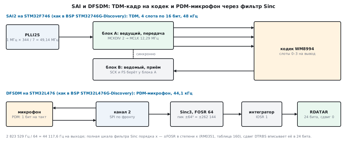
SAI. Inside there are two sub-blocks, A and B. Each has its own clock generator,
its own 8-word FIFO and its own choice: master or slave, transmit
or receive. The sub-blocks work independently or synchronously: the slave takes
the clock and frame start from its neighbour (SYNCEN = 01). This is how the STM32746G-Discovery board
writes to and reads from the codec with one SAI2 module: block A is the master transmitter,
block B is the slave receiver on the same SCK and FS wires.
What the frame can do (RM0385, 33.2):
- data size — 8, 10, 16, 20, 24 or 32 bits;
- up to 16 slots per frame, each can be enabled or skipped;
- frame length, length and polarity of the FS signal, its one-bit offset — all configurable;
- protocols I2S, MSB and LSB justified, PCM/DSP, TDM, AC'97, SPDIF output.
DFSDM. STM32L476 has one DFSDM1 module: 8 input channels and 4 filters (RM0351, table 155). A channel receives a bit stream from an external modulator — a PDM microphone — and can itself supply its clock on the CKOUT pin. A filter takes the stream of the selected channel, passes it through a Sinc filter of order 1…5, decimates by FOSR, optionally sums another IOSR outputs in the integrator and returns a signed 24-bit sample.
18б.2 The SAI frame: slots and the FS signal
The frame is set by three registers of a sub-block:
| Field | What it sets | STM32746G-Discovery |
|---|---|---|
FRL in SAI_xFRCR |
frame length − 1, in SCK clocks | 63: a 64-clock frame |
FSALL |
active FS duration − 1 | 31: FS active for 32 clocks |
FSDEF |
FS = frame start + left/right half | 1 |
FSPOL |
active level of FS | 0: low |
FSOFF |
FS one clock before the first bit of slot 0 | 1 |
NBSLOT in SAI_xSLOTR |
number of slots − 1 | 3: four slots |
SLOTSZ |
slot size | 0: equal to the data size, 16 bits |
SLOTEN |
which slots are enabled | A: all four; B: 0 and 2 |
The program built such a frame for the slots 0xA001, 0xB002, 0xC003,
0xD004, starting from the first bit of slot 0:
fs =0000000000000000000000000000000111111111111111111111111111111110
sd =1010000000000001101100000000001011000000000000111101000000000100
- FS is low for 32 clocks: 31 clocks in this frame and clock 63 — the start of
the next one: because of
FSOFF = 1the signal arrives one bit before the data; - with
FSDEF = 1the number of slots must be even: half are the left channel, half the right. Slots 0 and 1 go with FS low, 2 and 3 with FS high; - the program parsed the stream back and got
0xA001 0xB002 0xC003 0xD004.
This is TDM: four 16-bit channels in a frame that from outside looks like I2S. For recording, the board driver enables slots 0 and 2 (the codec's first digital microphone) or 1 and 3 (the second).
The registers of both sub-blocks, set register by register — sai18b_f7.c. The fields are taken
from the header stm32f746xx.h, and the result is checked with _Static_assert against what
HAL writes for the board driver settings:
#define SAI_A_CR1   ((4u << SAI_xCR1_DS_Pos) | SAI_xCR1_OUTDRIV | (MCKDIV << SAI_xCR1_MCKDIV_Pos))
#define SAI_B_CR1   (SAI_xCR1_MODE_1 | SAI_xCR1_MODE_0 | (4u << SAI_xCR1_DS_Pos) | SAI_xCR1_CKSTR | (1u << SAI_xCR1_SYNCEN_Pos))
#define SAI_FRCR    ((64u - 1u) | ((32u - 1u) << SAI_xFRCR_FSALL_Pos) | SAI_xFRCR_FSDEF | SAI_xFRCR_FSOFF)
#define SAI_A_SLOTR (((4u - 1u) << SAI_xSLOTR_NBSLOT_Pos) | (0xFu << SAI_xSLOTR_SLOTEN_Pos))
#define SAI_B_SLOTR (((4u - 1u) << SAI_xSLOTR_NBSLOT_Pos) | (0x5u << SAI_xSLOTR_SLOTEN_Pos))
void sai2_tdm4(void)
{
    SAI2_Block_B->CR1 = SAI_B_CR1;      /* приёмник: SCK и FS берёт у блока A */
    SAI2_Block_B->FRCR = SAI_FRCR;
    SAI2_Block_B->SLOTR = SAI_B_SLOTR;
    SAI2_Block_B->CR2 = SAI_xCR2_FTH_0; /* порог FIFO — четверть */

    SAI2_Block_A->CR1 = SAI_A_CR1;      /* передатчик и ведущий: выдаёт MCLK, SCK, FS */
    SAI2_Block_A->FRCR = SAI_FRCR;
    SAI2_Block_A->SLOTR = SAI_A_SLOTR;
    SAI2_Block_A->CR2 = SAI_xCR2_FTH_0;

    SAI2_Block_B->CR1 |= SAI_xCR1_SAIEN;  /* ведомый — первым */
    SAI2_Block_A->CR1 |= SAI_xCR1_SAIEN;
}
The result: block A — CR1 = 0x00202080, FRCR = 0x00051F3F, SLOTR = 0x000F0300;
block B — CR1 = 0x00000683, SLOTR = 0x00050300. The slave is enabled
first — that is what the manual recommends. HAL writes the same
MCKDIV = 2 into block B, but the slave's clock generator is off, and the divider
has no effect.
18б.3 SAI frame rate
The chain from RM0385 (33.3.8):
- MCLK = ker_ck / (MCKDIV · 2), and with
MCKDIV = 0— MCLK = ker_ck; - the ratio MCLK / fs is always 256;
- SCK = MCLK · (FRL + 1) / 256 — that is, SCK = 64 · fs for a 64-clock frame.
For the master the frame length must be a power of two, otherwise an SCK clock will not contain a whole even number of MCLK clocks. Table 210 of the manual: with ker_ck = 256 × 192 kHz dividers 0, 1, 2, 6 and 12 give 192, 96, 48, 16 and 8 kHz; with 256 × 44.1 kHz dividers 0, 1, 2 give 44.1, 22.05 and 11.025 kHz. The program recalculated all eight rows — they matched.
What the board does. The PLL input is 1 MHz (HSE_VALUE / PLL_M, as written in the display driver of the same board). The audio driver takes the SAI2 clock from PLLI2S:
- for 11.025, 22.05 and 44.1 kHz: N = 429, Q = 2, DIVQ = 19 — ker_ck = 11289473 Hz;
- for the rest: N = 344, Q = 7, DIVQ = 1 — ker_ck = 49142857 Hz.
HAL calculates the MCKDIV divider itself: ker_ck · 10 / (fs · 512), and rounds
up if the last digit is 9. For 48 kHz this gives 19, that is
MCKDIV = 2; without this rounding you would get MCKDIV = 1 and a frequency of
95982.143 Hz — twice as high. What you actually get:
| Rate | ker_ck, Hz | MCKDIV | Result, Hz | Error |
|---|---|---|---|---|
| 8000 | 49142857 | 12 | 7998.512 | −0.0186% |
| 11025 | 11289473 | 2 | 11024.877 | −0.0011% |
| 16000 | 49142857 | 6 | 15997.024 | −0.0186% |
| 22050 | 11289473 | 1 | 22049.753 | −0.0011% |
| 32000 | 49142857 | 3 | 31994.048 | −0.0186% |
| 44100 | 11289473 | 0 | 44099.507 | −0.0011% |
| 48000 | 49142857 | 2 | 47991.071 | −0.0186% |
| 96000 | 49142857 | 1 | 95982.143 | −0.0186% |
At 48 kHz SCK = 64 × 47991.071 = 3071429 Hz, MCLK = 49142857 / 4 = 12.29 MHz.
Can it be more accurate? The program went through all N (50…432, VCO 100…432 MHz), Q (2…15), DIVQ (1…32) and MCKDIV (0…15) with a 1 MHz input:
- for 44.1, 22.05 and 11.025 kHz the board's choice is the best possible;
- for 48 and 96 kHz too: 0.0186% is the limit with a 1 MHz input; the same limit came out in 18а for I2S with MCK;
- 8 kHz can be obtained exactly: N = 256, Q = 5, DIVQ = 25, MCKDIV = 0;
- 16 and 32 kHz with an error of 0.0038% instead of 0.0186%: N = 213, Q = 13, DIVQ = 1.
But there is one PLL for both rates, and the driver switches it only between two families. Exact 8 kHz would require reconfiguring PLLI2S — and everything clocked from it.
18б.4 DFSDM: the Sinc filter, the integrator and word width
A PDM microphone outputs one bit per clock: the louder the signal in that direction, the more ones in a row. The sound hides in the density of ones, and the quantization noise is pushed up in frequency. The filter's job is to cut off this noise and turn millions of bits per second into tens of thousands of multi-bit samples.
A Sinc filter of order x is x moving sums of length FOSR in a row, after
which every FOSR-th sample is kept. FORD sets the order (1…5
or the special FastSinc), FOSR the length and decimation (1…1024), IOSR —
how many filter outputs the integrator adds up (1…256).
Word width. The full scale at the output of a Sinc of order x is ±FOSRx, for FastSinc — ±2·FOSR², and the integrator multiplies it by IOSR as well (RM0351, tables 160 and 161). The program recalculated table 160: all 36 cells with numbers matched, and in the 5 cells where the manual says "may overflow", the peak really is larger than a 32-bit signed number. Some of the rows:
| FOSR | Sinc1 | Sinc2 | FastSinc | Sinc3 | Sinc4 | Sinc5 |
|---|---|---|---|---|---|---|
| 32 | ±32 | ±1024 | ±2048 | ±32768 | ±1048576 | ±33554432 |
| 64 | ±64 | ±4096 | ±8192 | ±262144 | ±16777216 | ±1073741824 |
| 256 | ±256 | ±65536 | ±131072 | ±16777216 | overflow | overflow |
All the arithmetic inside is in 32-bit signed registers, hence the manual's condition: FOSRFORD · IOSR ≤ 231. This also gives the FOSR limits: for Sinc1…Sinc3 — up to 1024, for Sinc4 — up to 215, for Sinc5 — up to 73. The program found them by brute force, and the manual gives the same numbers.
Shift. The result register RDATAR holds 24 signed bits
(bits 31:8). Extra bits are removed by the right shift DTRBS (0…31) —
with rounding to nearest and preserving the sign. Then the channel
offset OFFSET is subtracted. The rule is simple: the peak after the shift must
stay below 223.
Conversion time (RM0351, 24.4.8): the first one is [FOSR · (IOSR − 1 + FORD) + FORD]
input clocks, after that in continuous mode with FAST = 1 — FOSR · IOSR clocks.
For Sinc3 and FOSR 64 that is 195 clocks for the first sample and 64 for each
following one: 69.1 µs and 22.67 µs at a 2.82 MHz clock.
18б.5 The microphone on STM32L476G-Discovery
The board driver clocks DFSDM from the audio PLL PLLSAI1 (8 MHz input):
11.294 MHz (× 24 / 17) for the 44.1 kHz family and 49.143 MHz (× 43 / 7)
for the rest. The microphone is connected to channel 2, the filter is filter zero, Sinc3…Sinc5
and FOSR are chosen for each rate, IOSR = 1:
| Rate | CKOUT divider | Microphone clock, Hz | Filter | FOSR | Result, Hz | Error | Peak | Shift | After shift |
|---|---|---|---|---|---|---|---|---|---|
| 8000 | 24 | 2047619 | Sinc3 | 256 | 7998.51 | −0.019% | 224 | 6 | 218 |
| 11025 | 4 | 2823529 | Sinc3 | 256 | 11029.41 | +0.040% | 224 | 6 | 218 |
| 16000 | 24 | 2047619 | Sinc3 | 128 | 15997.02 | −0.019% | 221 | 3 | 218 |
| 22050 | 4 | 2823529 | Sinc3 | 128 | 22058.82 | +0.040% | 221 | 3 | 218 |
| 32000 | 24 | 2047619 | Sinc4 | 64 | 31994.05 | −0.019% | 224 | 6 | 218 |
| 44100 | 4 | 2823529 | Sinc3 | 64 | 44117.65 | +0.040% | 218 | 0 | 218 |
| 48000 | 32 | 1535714 | Sinc4 | 32 | 47991.07 | −0.019% | 220 | 2 | 218 |
| 96000 | 32 | 1535714 | Sinc5 | 16 | 95982.14 | −0.019% | 220 | 0 | 220 |
You can see how the shift is chosen: for all rates except 96 kHz the peak after it is exactly 218. The 44.1 kHz family here is noticeably less accurate than with SAI on F746: +0.040% versus −0.0011%.
The driver then shifts the register by 8 (>> 8 keeps the whole 24-bit
sample without the service bits) and saturates it to ±32767, that is, to 16 bits.
But a peak of 218 is 8 times larger than 32768 — that is 18.1 dB: the upper part
of the modulator's scale never reaches the program, and a loud sound gets clipped.
For 96 kHz the peak is four times higher still.
The 44.1 kHz setup, register by register — dfsdm18b_l4.c (the SAI1 clock is already
configured, DMA — as in section 9):
#define CH0_CFGR1 (DFSDM_CHCFGR1_CKOUTSRC | ((CKOUT_DIV - 1u) << DFSDM_CHCFGR1_CKOUTDIV_Pos))
#define CH2_CFGR1 (1u << DFSDM_CHCFGR1_SPICKSEL_Pos)   /* SITP = 00: SPI, данные по фронту */
#define FLT_FCR   ((FORD << DFSDM_FLTFCR_FORD_Pos) | ((FOSR - 1u) << DFSDM_FLTFCR_FOSR_Pos) | (IOSR - 1u))
#define FLT_CR1   (DFSDM_FLTCR1_FAST | (2u << DFSDM_FLTCR1_RCH_Pos) | DFSDM_FLTCR1_RDMAEN | DFSDM_FLTCR1_RCONT)
void dfsdm_mic_44k(void)
{
    RCC->APB2ENR |= RCC_APB2ENR_DFSDM1EN;
    DFSDM1_Channel0->CHCFGR1 = CH0_CFGR1;           /* CKOUT задаётся при DFSDMEN = 0 */
    DFSDM1_Channel2->CHCFGR2 = SHIFT << DFSDM_CHCFGR2_DTRBS_Pos;
    DFSDM1_Channel2->CHCFGR1 = CH2_CFGR1;           /* SPICKSEL — при CHEN = 0 */
    DFSDM1_Channel2->CHCFGR1 |= DFSDM_CHCFGR1_CHEN;
    DFSDM1_Channel0->CHCFGR1 |= DFSDM_CHCFGR1_DFSDMEN;

    DFSDM1_Filter0->FLTFCR = FLT_FCR;               /* пишется при DFEN = 0 */
    DFSDM1_Filter0->FLTCR1 = FLT_CR1;
    DFSDM1_Filter0->FLTCR1 |= DFSDM_FLTCR1_DFEN;
    DFSDM1_Filter0->FLTCR1 |= DFSDM_FLTCR1_RSWSTART;
}
The values: CH0CFGR1 = 0x40030000 (clock output from the audio clock,
divider 4), CH2CFGR1 = 0x00000084 after the channel is enabled,
FLT0FCR = 0x603F0000 (Sinc3, FOSR 64, IOSR 1), FLT0CR1 = 0x22240000
before DFEN. The _Static_assert checks verify these numbers, the condition
FOSR3 · IOSR ≤ 231, and that the result fits in 24 bits.
Reading with saturation to 16 bits, as in the driver:
int16_t dfsdm_read16(void)
{
    int32_t v = (int32_t)DFSDM1_Filter0->FLTRDATAR >> 8;
    return (int16_t)(v > 32767 ? 32767 : (v < -32768 ? -32768 : v));
}
armclang (-O2) compiled it into a single saturation instruction:
MOV      r0,#0x611c
MOVT     r0,#0x4001
LDR      r0,[r0,#0]
SSAT     r0,#16,r0,ASR #8
BX       lr
SSAT with a shift does both >> 8 and the clipping to 16 bits; the address
0x4001 611C is DFSDM1_FLT0RDATAR.
18б.6 Model: a PDM stream through a Sinc filter
How the order and FOSR affect quality was checked by the program on a model. A 2nd-order sigma-delta modulator turns a half-amplitude sine into a ±1 stream at 3.072 MHz; the stream passes through a Sinc filter in integers, as in DFSDM, with a shift to 24 bits; over 2048 output samples the signal-to-noise ratio (SNR) is calculated over the whole band up to half the sample rate. Scale check: a stream of all ones after Sinc3 with FOSR 64 gives 262144, after Sinc5 — 1073741824, as in table 160.
Filter order at FOSR 64 (48 kHz):
| Filter | Shift | SNR |
|---|---|---|
| Sinc1 | 0 | 27.5 dB |
| Sinc2 | 0 | 58.8 dB |
| Sinc3 | 0 | 75.2 dB |
| Sinc4 | 2 | 78.6 dB |
| Sinc5 | 8 | 80.9 dB |
Sinc1 is almost useless: the noise the modulator pushed up folds back into the audio band during decimation. For a 2nd-order modulator the gain above Sinc3 is a few decibels.
Decimation with Sinc3:
| FOSR | Sample rate | SNR |
|---|---|---|
| 16 | 192 kHz | 44.5 dB |
| 32 | 96 kHz | 60.1 dB |
| 64 | 48 kHz | 75.2 dB |
| 128 | 24 kHz | 90.4 dB |
Each doubling of FOSR gives about 15 dB. At 96 kHz, where FOSR is only 16, the board driver takes the highest order — Sinc5.
Droop in the band. Sinc is not a brick-wall filter; it also attenuates the top of the audio range. At FOSR 64 and 48 kHz: Sinc3 loses 0.02 dB at 1 kHz, 1.89 dB at 10 kHz and 7.92 dB at 20 kHz; Sinc5 — 0.03, 3.15 and 13.20 dB. The model confirms the formula: a 10007.8 Hz sine after Sinc3 is 1.87 dB quieter than a sine at about 1 kHz, and the formula for the same frequencies gives 1.87 dB. If the droop is a problem, it is equalized with your own filter after DFSDM.
A real microphone is built differently: the order of its modulator and its noise are not included in the model, so the SNR numbers are only for comparing settings with each other.
18б.7 Pitfalls
The rate is twice as high. MCKDIV was calculated without rounding: for 48 kHz
at 49.14 MHz the ratio ker_ck / (fs · 512) is slightly less than 2 (in the HAL calculation
with a factor of 10 — 19), the integer part is 1, and you get 96 kHz. HAL rounds
up if the last digit is 9; when calculating by hand you must do the same.
There is SCK but no FS. A master transmitter outputs the clock right after
SAIEN, but FS only once data has appeared in the FIFO (RM0385, 33.3.3).
Start DMA or write the first word first, then wait for the frame.
A frame of the required length cannot be configured. With NODIV = 0 the master's frame
length can only be a power of two: otherwise a bit does not contain a whole
even number of MCLK clocks. For a frame of another length use NODIV = 1
and ker_ck equal to SCK.
The slots are mixed up. With FSDEF = 1 the first half of the slots goes while
FS is active, the second while it is inactive. With FSPOL = 0 the active level is
low — the "left" slots 0 and 1 go with FS = 0.
The receiver reads garbage although the transmitter is fine. The same
ClockStrobing setting in HAL gives a different CKSTR bit: 0 for
the transmitter and 1 for the receiver. When configuring by registers this is easy
to forget.
The slave sub-block misses the beginning. It was enabled after the master:
the slave starts a frame only from the nearest FS after SAIEN. The manual
recommends enabling the slave first.
DFSDM settings are not applied. CKOUTDIV and CKOUTSRC can be written only
with DFSDMEN = 0, SPICKSEL with CHEN = 0, FORD, FOSR, IOSR,
FAST and RDMAEN with DFEN = 0. Configure first, then set the enable bit.
Loud sound wheezes. The filter peak is larger than fits in 16 bits,
and the DTRBS shift is too small: saturation clips the top of the scale. Choose the shift so that
the peak after it fits into the required width.
The result overflowed. FOSRFORD · IOSR is greater than 231: for example, Sinc5 with FOSR above 73 or Sinc4 with FOSR above 215.
18б.8 Summary
- SAI is two sub-blocks A and B with their own generators and 8-word FIFOs; a frame of up to 16 slots, TDM and I2S with the same hardware; a slave sub-block synchronously takes SCK and FS from its neighbour.
- MCLK = ker_ck / (2 · MCKDIV), MCLK = 256 · fs, SCK = MCLK · (FRL + 1) / 256; on STM32746G-Discovery 48 kHz is 47991.071 Hz (−0.0186%), 44.1 kHz is 44099.507 Hz (−0.0011%), and with a 1 MHz PLL input it cannot be better.
- The board's frame: 64 clocks, 4 slots of 16 bits, FS low for 32 clocks one bit before
the data; block A —
0x00202080,0x00051F3F,0x000F0300. - DFSDM: the peak of a Sinc of order x is ±FOSRx, the condition is FOSRFORD · IOSR ≤ 231; FOSR up to 215 for Sinc4 and up to 73 for Sinc5; table 160 — 36 out of 36 cells.
- STM32L476G-Discovery: Sinc3, FOSR 64, a 2.82 MHz clock — 44117.65 Hz (+0.040%), a peak of 218 — 18.1 dB more than 16 bits after saturation.
- A 2nd-order modulator model: Sinc3 at FOSR 64 gives 75.2 dB, Sinc1 — 27.5 dB; each doubling of FOSR gives about 15 dB.
Full sources
sai18b_f7.c — SAI2 on STM32F746, register by register: 4-slot TDM, 48 kHz.
/* 18б: SAI2 на STM32F746 по регистрам — TDM 4 слота по 16 бит, 48 кГц, как в BSP STM32746G-Discovery.
   Собирается armclang: -DSTM32F746xx. Вход PLLI2S — 1 МГц (HSE_VALUE / PLL_M, как в BSP платы). */
#include <stdint.h>

#define I2SN   344u                     /* VCO 344 МГц */
#define I2SQ   7u                       /* 344 / 7 = 49,142857 МГц */
#define MCKDIV 2u                       /* MCLK = 49,142857 / 4 = 12,285714 МГц = 256 x 47 991 Гц */

#define SAI_A_CR1   ((4u << SAI_xCR1_DS_Pos) | SAI_xCR1_OUTDRIV | (MCKDIV << SAI_xCR1_MCKDIV_Pos))
#define SAI_B_CR1   (SAI_xCR1_MODE_1 | SAI_xCR1_MODE_0 | (4u << SAI_xCR1_DS_Pos) | SAI_xCR1_CKSTR | (1u << SAI_xCR1_SYNCEN_Pos))
#define SAI_FRCR    ((64u - 1u) | ((32u - 1u) << SAI_xFRCR_FSALL_Pos) | SAI_xFRCR_FSDEF | SAI_xFRCR_FSOFF)
#define SAI_A_SLOTR (((4u - 1u) << SAI_xSLOTR_NBSLOT_Pos) | (0xFu << SAI_xSLOTR_SLOTEN_Pos))
#define SAI_B_SLOTR (((4u - 1u) << SAI_xSLOTR_NBSLOT_Pos) | (0x5u << SAI_xSLOTR_SLOTEN_Pos))

_Static_assert(SAI_A_CR1 == 0x00202080u, "A: ведущий передатчик, 16 бит, MCKDIV = 2");
_Static_assert(SAI_B_CR1 == 0x00000683u, "B: ведомый приёмник, синхронно с A");
_Static_assert(SAI_FRCR == 0x00051F3Fu, "кадр 64 такта, FS 32 такта, FSDEF, FSOFF, FS активен низким");
_Static_assert(SAI_A_SLOTR == 0x000F0300u && SAI_B_SLOTR == 0x00050300u, "4 слота; A — все, B — 0 и 2");
_Static_assert(RCC_PLLI2SCFGR_PLLI2SN_Pos == 6 && RCC_PLLI2SCFGR_PLLI2SQ_Pos == 24, "поля PLLI2S");

void sai_clock_48k(void)
{
    RCC->CR &= ~RCC_CR_PLLI2SON;
    while (RCC->CR & RCC_CR_PLLI2SRDY) {
    }
    RCC->PLLI2SCFGR = (I2SN << RCC_PLLI2SCFGR_PLLI2SN_Pos) | (I2SQ << RCC_PLLI2SCFGR_PLLI2SQ_Pos)
                    | (2u << RCC_PLLI2SCFGR_PLLI2SR_Pos);
    RCC->DCKCFGR1 = (RCC->DCKCFGR1 & ~(RCC_DCKCFGR1_PLLI2SDIVQ | RCC_DCKCFGR1_SAI2SEL))
                  | (0u << RCC_DCKCFGR1_PLLI2SDIVQ_Pos)      /* DIVQ = 1 */
                  | (1u << RCC_DCKCFGR1_SAI2SEL_Pos);        /* SAI2 от PLLI2S */
    RCC->CR |= RCC_CR_PLLI2SON;
    while (!(RCC->CR & RCC_CR_PLLI2SRDY)) {
    }
    RCC->APB2ENR |= RCC_APB2ENR_SAI2EN;
}

void sai2_tdm4(void)
{
    SAI2_Block_B->CR1 = SAI_B_CR1;      /* приёмник: SCK и FS берёт у блока A */
    SAI2_Block_B->FRCR = SAI_FRCR;
    SAI2_Block_B->SLOTR = SAI_B_SLOTR;
    SAI2_Block_B->CR2 = SAI_xCR2_FTH_0; /* порог FIFO — четверть */

    SAI2_Block_A->CR1 = SAI_A_CR1;      /* передатчик и ведущий: выдаёт MCLK, SCK, FS */
    SAI2_Block_A->FRCR = SAI_FRCR;
    SAI2_Block_A->SLOTR = SAI_A_SLOTR;
    SAI2_Block_A->CR2 = SAI_xCR2_FTH_0;

    SAI2_Block_B->CR1 |= SAI_xCR1_SAIEN;  /* ведомый — первым */
    SAI2_Block_A->CR1 |= SAI_xCR1_SAIEN;
}
dfsdm18b_l4.c — DFSDM on STM32L476, register by register: PDM microphone, 44.1 kHz.
/* 18б: DFSDM на STM32L476 по регистрам — PDM-микрофон на канале 2, фильтр 0, 44,1 кГц,
   как в BSP STM32L476G-Discovery. Собирается armclang: -DSTM32L476xx.
   Такт SAI1 = 11,294 МГц (PLLSAI1: 8 МГц x 24 / 17) настроен заранее. */
#include <stdint.h>

#define CKOUT_DIV 4u                    /* CKOUT = 11,294 / 4 = 2,8235 МГц — такт микрофона */
#define FORD      3u                    /* Sinc3 */
#define FOSR      64u                   /* 2,8235 МГц / 64 = 44 117,6 Гц */
#define IOSR      1u                    /* интегратор не нужен */
#define SHIFT     0u                    /* пик 64^3 = 2^18 и так влезает в 24 бита */

#define CH0_CFGR1 (DFSDM_CHCFGR1_CKOUTSRC | ((CKOUT_DIV - 1u) << DFSDM_CHCFGR1_CKOUTDIV_Pos))
#define CH2_CFGR1 (1u << DFSDM_CHCFGR1_SPICKSEL_Pos)   /* SITP = 00: SPI, данные по фронту */
#define FLT_FCR   ((FORD << DFSDM_FLTFCR_FORD_Pos) | ((FOSR - 1u) << DFSDM_FLTFCR_FOSR_Pos) | (IOSR - 1u))
#define FLT_CR1   (DFSDM_FLTCR1_FAST | (2u << DFSDM_FLTCR1_RCH_Pos) | DFSDM_FLTCR1_RDMAEN | DFSDM_FLTCR1_RCONT)

_Static_assert(CH0_CFGR1 == 0x40030000u, "CKOUT от звукового такта, делитель 4");
_Static_assert((CH2_CFGR1 | DFSDM_CHCFGR1_CHEN) == 0x00000084u, "канал 2: SPI по фронту, такт — CKOUT");
_Static_assert(FLT_FCR == 0x603F0000u, "Sinc3, FOSR 64, IOSR 1");
_Static_assert(FLT_CR1 == 0x22240000u, "FAST, RCH = 2, DMA, непрерывно");
_Static_assert(FOSR * FOSR * FOSR * IOSR <= (1u << 31), "FOSR^FORD * IOSR <= 2^31 (RM0351)");
_Static_assert(((FOSR * FOSR * FOSR * IOSR) >> SHIFT) < (1u << 23), "результат влезает в 24 бита со знаком");

void dfsdm_mic_44k(void)
{
    RCC->APB2ENR |= RCC_APB2ENR_DFSDM1EN;
    DFSDM1_Channel0->CHCFGR1 = CH0_CFGR1;           /* CKOUT задаётся при DFSDMEN = 0 */
    DFSDM1_Channel2->CHCFGR2 = SHIFT << DFSDM_CHCFGR2_DTRBS_Pos;
    DFSDM1_Channel2->CHCFGR1 = CH2_CFGR1;           /* SPICKSEL — при CHEN = 0 */
    DFSDM1_Channel2->CHCFGR1 |= DFSDM_CHCFGR1_CHEN;
    DFSDM1_Channel0->CHCFGR1 |= DFSDM_CHCFGR1_DFSDMEN;

    DFSDM1_Filter0->FLTFCR = FLT_FCR;               /* пишется при DFEN = 0 */
    DFSDM1_Filter0->FLTCR1 = FLT_CR1;
    DFSDM1_Filter0->FLTCR1 |= DFSDM_FLTCR1_DFEN;
    DFSDM1_Filter0->FLTCR1 |= DFSDM_FLTCR1_RSWSTART;
}

/* 24 бита со знаком лежат в RDATAR[31:8]; до 16 бит — с насыщением, как в BSP */
int16_t dfsdm_read16(void)
{
    int32_t v = (int32_t)DFSDM1_Filter0->FLTRDATAR >> 8;
    return (int16_t)(v > 32767 ? 32767 : (v < -32768 ? -32768 : v));
}
Next: section 18в "A synthesizer on STM32: a look at the Mutable Instruments modules — codec, sample block and real-time DSP" — how I2S, DMA and block calculation come together in real open-source Eurorack modules.