 Embedded HandbookApps
18а. Audio over I2S: the frame, the formats and an exact sample rate
I2S is a serial interface for digital audio: the microcontroller sends samples to a codec (a DAC with an amplifier) or receives them from a digital microphone or an ADC. On the STM32F4 it is not a separate block but the second mode of the SPI2 and SPI3 modules. The main difficulty with I2S is not in the bits but in the frequency: the codec expects exactly 44 100 or 48 000 samples per second, while the chip's clock frequency does not divide into them. For this the F4 has a separate PLL — PLLI2S.
The frame rules, the divider formulas and the PLL limits are taken from the reference
manual for the F405/F407 (from the Keil pack). The frame and the packing of a 24-bit
word are built by the program _verify/i2s18a/i2sframe.c, the frequencies by an exhaustive search over
all allowed dividers in _verify/i2s18a/i2sclk.c; both are built with gcc
on a computer. Checked by _verify/i2s18a_check.py.
Terms used in the documentation
Term Meaning serial clock (CK) the bit clock word select (WS) the channel select: left or right serial data (SD) the data line master clock (MCK), MCKOE the clock for the codec and the bit that outputs it Philips, MSB justified, LSB justified, PCM the four frame standards channel side (CHSIDE) a flag showing which channel is being transmitted PLLI2S, I2SDIV, ODD the audio PLL and the I2S frequency divider full duplex (I2Sx_ext) simultaneous transmission and reception
18а.1 Four wires
| Signal | What it carries |
|---|---|
| CK | the bit clock |
| WS | which channel is going: 0 — left, 1 — right |
| SD | the data, most significant bit first |
| MCK | the clock for the codec — 256 × the sample rate; optional |
There are two channels, and the left one is always first. There is one data register, 16 bits wide:
the program (or DMA) writes samples into it in turn, and the CHSIDE flag
shows whose turn it is now. There is no incomplete frame — only the left one
together with the right one.
There are four frame standards: Philips (also called "I2S"), MSB justified,
LSB justified and PCM. A codec supports one or several —
its documentation tells you which one to choose in I2SSTD.
18а.2 The Philips frame
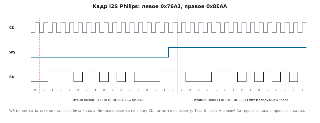
The main feature of the Philips standard: WS changes one clock before the most significant bit of the channel. The transmitter sets a bit on the falling edge of CK, the receiver reads on the rising edge.
The program built a frame of 16 bits × 2 channels for the left word 0x76A3
(the one given in the manual) and the right one 0x8EAA:
ws =00000000000000001111111111111111
sd =00111011010100011100011101010101
- WS rises at clock 16, and the most significant bit of the right channel at clock 17;
- bits 1…16 are the left word
0111 0110 1010 0011=0x76A3; - clock 0 carries the least significant bit of the right channel of the previous frame — because of the same
one-clock delay. The program assembled both words back from the bit stream
and got
0x76A3and0x8EAA.
In MSB justified there is no such delay: WS changes together with the most significant bit. Mixing up Philips and MSB justified means shifting all samples by a bit: the sound becomes distorted and wheezy.
18а.3 Data formats
| Data in the channel | Register writes per channel | What the hardware does |
|---|---|---|
| 16 bits in a 16-bit channel | 1 | — |
| 16 bits in a 32-bit channel | 1 | the lower 16 bits are zeros by themselves |
| 24 bits in a 32-bit channel | 2 | the lower 8 bits are zeros by themselves |
| 32 bits in a 32-bit channel | 2 | — |
A 24-bit sample is written as two words: the upper 16 bits, then the lower 8 in the
upper byte of the second word. For 0x8EAA33 the program gives 0x8EAA,
then 0x33XX — the lower byte of the second word means nothing. The same
is in the manual.
The frame size: 16 × 2 = 32 bits with 16-bit channels, 32 × 2 = 64 with 32-bit ones. Hence the CK frequency: at 48 kHz and 16 bits — 48 000 × 32 = 1 536 000 Hz. MCK for the codec — 256 × 48 000 = 12 288 000 Hz.
18а.4 Where the sample rate comes from
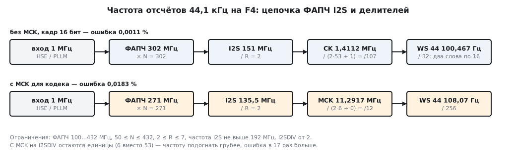
The chain: the PLL input (1 or 2 MHz after the common PLLM divider) × N / R — gives the I2S frequency; then the divider 2·I2SDIV + ODD:
| MCK | Frame | Sample rate |
|---|---|---|
| off | 16 bits | fI2S / [32 · (2·I2SDIV + ODD)] |
| off | 32 bits | fI2S / [64 · (2·I2SDIV + ODD)] |
| on | any | fI2S / [256 · (2·I2SDIV + ODD)] |
Limits from the manual: the PLL oscillator output is 100…432 MHz, 50 ≤ N ≤ 432, 2 ≤ R ≤ 7, the I2S frequency no more than 192 MHz, I2SDIV from 2 (0 and 1 are forbidden). The input is 1…2 MHz; the manual recommends 2 MHz — less jitter.
Searching all variants. The program went through N, R, I2SDIV and ODD and for each frequency found the smallest error. With a 1 MHz input all the examples from the manual's table turned out to be the best possible — the search found nothing more exact. Some of them:
| Frequency | MCK | N | R | I2SDIV | ODD | Result | Error |
|---|---|---|---|---|---|---|---|
| 48 000 | no, 16 bits | 192 | 5 | 12 | 1 | 48 000 | 0 |
| 44 100 | no, 16 bits | 302 | 2 | 53 | 1 | 44 100.467 | 0.0011 % |
| 48 000 | yes | 258 | 3 | 3 | 1 | 47 991.071 | 0.0186 % |
| 44 100 | yes | 271 | 2 | 6 | 0 | 44 108.073 | 0.0183 % |
Without MCK the divider is large, and the frequency can be matched almost exactly. With MCK the overall divider is already 256 times larger, only single units remain for I2SDIV — for 44.1 kHz the error grows 17 times.
A 1 or 2 MHz input. The PLLM divider is shared with the main PLL, so the input is chosen once for the whole chip. With MCK:
| Frequency | 1 MHz input | 2 MHz input |
|---|---|---|
| 8 000 | 0 | 0 |
| 22 050 | 0.0011 % | 0.0063 % |
| 44 100 | 0.0183 % | 0.0344 % |
| 48 000 | 0.0186 % | 0.0186 % |
So the advice "a 2 MHz input for less jitter" makes the frequency accuracy almost twice worse for 44.1 kHz with MCK. An error of 0.03 % is not audible (about 0.6 cent — 0.6 hundredths of a semitone), but in a recording with an external timer it accumulates: 44 100 × 0.000344 ≈ 15 samples per second too many or too few. If you need an exact zero — an external audio clock on the I2S_CKIN input. For 48 kHz without MCK 12.288 MHz is enough (I2SDIV = 4, a 16-bit frame), with MCK you need 49.152 MHz: I2SDIV is never less than 2, and 12.288 MHz with MCK give no more than 12 kHz. For 44.1 kHz there is its own family: 11.2896 MHz without MCK, 45.1584 MHz with MCK. Or the codec with its own crystal is made the master, and the STM32 works as a slave.
A detail for the attentive: the frequencies in the manual's table differ from the exact ones in thousandths of a hertz (44 100.46875 against 44 100.46729) — the table was computed with rounding; this does not affect the error percentages.
18а.5 The stream: DMA and a double buffer
Audio is a continuous stream: if a sample is not written before the end of the current one, you hear a click. So I2S is almost always fed by DMA in circular mode (section 9):
- the buffer is divided into two halves; DMA transmits one, and the "half transferred" interrupt gives the program time to fill it again;
- the time to fill a half is its duration: 256 frames at 48 kHz — 256 / 48 000 = 5.33 ms;
- 16-bit stereo: a frame is two halfwords; a half of 256 frames is 512 halfwords, the whole buffer 1024.
Transmission and reception at the same time — the I2Sx and I2Sx_ext pair: the main module is the master and outputs CK and WS, the additional one works only as a slave and only in full-duplex mode.
Disable I2S only after TXE = 1 and BSY = 0, otherwise the last sample
will be cut off.
18а.6 Pitfalls
The sound wheezes. The frame standard of the codec and of the STM32 differ (Philips against MSB justified) — all bits are shifted by one.
The channels swapped places. The first sample in the buffer is the left one; shifting the buffer
by one halfword swaps the channels. In slave mode (and with I2Sx_ext) the cause
can also be the start-up: the block is enabled when WS has the right level — high in
the Philips standard, low in MSB, LSB and PCM; enabled in the middle of a channel, it
will start the frame from the wrong word.
The pitch is "lower" than it should be. The I2S frequency was computed without taking MCK into account: with MCK enabled the divider is 8 times (16-bit frame) or 4 times (32-bit) larger.
44.1 kHz with a 0.03 % error. The PLL input is 2 MHz. With a 1 MHz input it is 0.018 %; an exact zero only with an external audio clock on I2S_CKIN (18а.4).
24-bit audio "falls apart". The second halfword is written with the lower byte down; the lower 8 bits of the sample must lie in the upper byte of the second word.
Clicks every few milliseconds. The program does not manage to fill half of the buffer within its duration. A larger buffer or less work in the interrupt.
I2SDIV = 1 "works" wrongly. The values 0 and 1 are forbidden.
18а.7 Summary
- I2S is a mode of SPI2/SPI3: CK, WS, SD and an optional MCK; left channel first, most significant bit first.
- Philips: WS one clock before the most significant bit; clock 0 of a frame carries the least significant bit of the right channel of the previous frame.
- 24 bits — two writes:
0x8EAA33→0x8EAA,0x33XX. - 48 kHz × 16 bits × 2 = 1.536 MHz on CK; MCK = 256 × fs = 12.288 MHz.
- The manual's examples for PLLI2S are the best possible with a 1 MHz input; with MCK 44.1 kHz gives 0.0183 % (1 MHz input) or 0.0344 % (2 MHz input).
- The stream is circular DMA with two halves; 256 frames at 48 kHz give 5.33 ms to fill a half.
Next: section 18б "SAI and DFSDM: multichannel audio and digital microphones" — the SAI audio block with a frame of up to 16 slots and the filter for PDM microphones.