 Embedded HandbookApps
18в. A synthesizer on STM32: a look at the Mutable Instruments modules — codec, sample block and real-time DSP
In sections 18а and 18б audio went through I2S and SAI: the frame, the sample rate, the DMA double buffer. Mini-project 198п had its own simple synthesizer on a DAC. Here we look at how the same techniques come together in real instruments: the Eurorack modules made by Mutable Instruments. Their sources and schematics are open, the modules were produced in series, and the code shows everything: which codec, which sample block, how a control voltage turns into a note and how the oscillator gets by without aliasing.
The walk-through follows the signal path: control input → ADC → calibration → block calculation → DMA → I2S → codec. The oscillator and filter code of the Braids module was built on a PC and checked by experiment: tuning accuracy, the filter frequency response, the spectrum of a sawtooth with polynomial BLEP and without it.
Sources: the Mutable Instruments eurorack project (github.com/pichenettes/eurorack,
commit 08460a6, author Émilie Gillet): the module makefiles,
the drivers */drivers/codec.cc, plaits/drivers/audio_dac.cc, plaits/ui.cc,
plaits/settings.cc, braids/braids.cc, braids/analog_oscillator.cc,
braids/svf.h, the table generator braids/resources/lookup_tables.py and the schematics
*/hardware_design/pcb/*.sch. License: the STM32 code is MIT, the schematics and
boards are CC-BY-SA 3.0 (the project README); the quotations below carry this note.
STM32F405 registers follow the header stm32f405xx.h and HAL F4 (pack STM32F4xx_DFP 2.17.1). Besides the walk-through —
a small synthesizer voice of our own in C: a V/OCT input with calibration, a sawtooth with
polyBLEP, a filter and a block for DMA, plus a register-level setup of I2S and DMA on F405 —
complete, so you can repeat it. Filters in general are covered in section 81а,
the exact I2S frequency in 18а.
Terms used in the documentation
Term Meaning control voltage (CV) a voltage that controls a parameter 1 V/octave (V/OCT) one volt per octave: +1 V is a note an octave higher gate, trigger a "key pressed" level and a short start pulse codec, audio DAC codec (audio ADC + DAC), audio DAC block size how many samples are calculated per call half transfer / transfer complete DMA "half" and "end" of buffer interrupts phase increment phase step per sample band-limited step (BLEP), polyBLEP a correction to a signal step against aliasing aliasing harmonics above half the sample rate "fold" back down state variable filter (SVF) a filter giving low-pass, band-pass and high-pass at once damping, resonance filter damping and resonance; quality factor Q = 1 / damping lookup table (LUT) a table of precomputed values
18в.1 Modules and microcontrollers
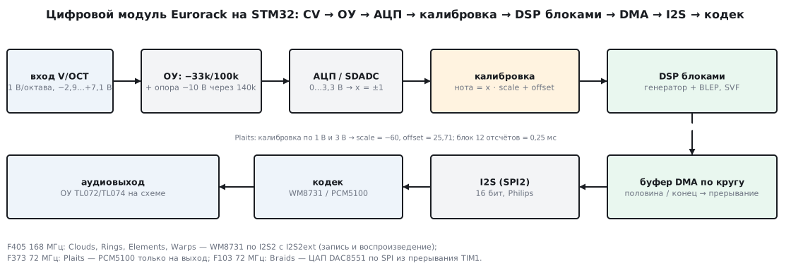
Eurorack is a format of modular synthesizers: each module is a separate panel in a shared case, and modules are connected with patch cables. The cables carry audio and control voltages: note pitch (1 V per octave), envelopes, "key pressed" levels (gate) and start pulses (trigger). Power comes from the shared bipolar bus of the case; the project files do not give the exact bus voltages, so they are not stated here.
Which module runs on which microcontroller is visible from FAMILY and F_CPU
in the makefile and from the part designations on the schematics:
| Module | What it does | MCU on the schematic | F_CPU |
Audio output |
|---|---|---|---|---|
| Braids | oscillator | STM32F103CBT6 | 72 MHz | DAC8551 DAC over SPI |
| Plaits | oscillator | STM32F373CCT6 | 72 MHz | PCM5100 over I2S |
| Clouds | granular processing | STM32F405RGT6 | 168 MHz | WM8731 over I2S |
| Rings | resonator | STM32F405RGT6 | 168 MHz | WM8731 over I2S |
| Elements | modal synthesis | STM32F405RGT6 | 168 MHz | WM8731 over I2S |
| Warps | modulator | STM32F405RGT6 | 168 MHz | WM8731 over I2S |
Tides, Peaks, Frames, Streams and Yarns are also STM32F103 (FAMILY = f10x),
Stages and Tides 2 are STM32F373 (f37x), Marbles is F405 (f4xx).
The split is simple. Where an audio input is needed (Clouds, Rings, Elements,
Warps process an external signal) — F405 and the WM8731 codec: ADC and DAC in
one package. Where audio only goes out — F373 and the PCM5100 DAC, or F103 and
the DAC8551 DAC. F373 has 16-bit sigma-delta ADCs for the control inputs
(SDADC), and that is how V/OCT is read in Plaits.
This repository alone is not enough to build. Every makefile ends with
the line include stmlib/makefile.inc, and stmlib in the project is a git
submodule whose folder is empty in the repository archive. So below the Braids code was built
in parts — with a short replacement for those stmlib functions without which it does not
compile (see 18в.4).
18в.2 The codec, I2S and the DMA double buffer
F405 and WM8731. All four F405 modules connect the codec the same way:
configuration over I2C2 (address 0x1A), audio over I2S2, with transmission going
through SPI2 and reception through the extra module I2S2ext, as in 18а.
Transmission is driven by DMA1 Stream4, reception by DMA1 Stream3, both circular,
in half-words. Only the receive stream's interrupt is used — and it
triggers the calculation of both halves:
void DMA1_Stream3_IRQHandler(void) {
  if (AUDIO_I2S_EXT_DMA_REG->AUDIO_I2S_EXT_DMA_ISR & AUDIO_I2S_EXT_DMA_FLAG_TC) {
    AUDIO_I2S_EXT_DMA_REG->AUDIO_I2S_EXT_DMA_IFCR = AUDIO_I2S_EXT_DMA_FLAG_TC;
    rings::Codec::GetInstance()->Fill(1);
  }
  if (AUDIO_I2S_EXT_DMA_REG->AUDIO_I2S_EXT_DMA_ISR & AUDIO_I2S_EXT_DMA_FLAG_HT) {
    AUDIO_I2S_EXT_DMA_REG->AUDIO_I2S_EXT_DMA_IFCR = AUDIO_I2S_EXT_DMA_FLAG_HT;
    rings::Codec::GetInstance()->Fill(0);
  }
}
(rings/drivers/codec.cc, MIT.) The flags are read directly from the registers:
according to the author's comment — to avoid spending library function calls.
Fill(0) calculates the first half while DMA transfers the second, Fill(1) —
the other way round. The buffer length is 2 * stride * block_size * 2 half-words: two
channels, two halves. Rings has a 24-frame block; with the STM32 as master
(stride = 1) that is 96 half-words.
stride is the second mode. In the revised board the codec becomes the
master, and then, as the code says, the data comes "padded": at 48 kHz
every second slot is empty (stride = 2), at 32 kHz — two out of three.
Fill packs the samples tightly before the calculation and spreads them back out after it.
Frequency. The I2S clock comes from a separate PLL, PLLI2S. The numbers N and R in the driver are chosen "for an 8 MHz crystal"; if the PLL input is 1 MHz, the I2S divider (with MCLK output, fs = I2SCLK / (256 · divider)) gives what is written in the comments:
| Rate | N / R | I2SCLK, Hz | Divider | Result, Hz | Error | Comment in the code |
|---|---|---|---|---|---|---|
| 48000 | 258 / 3 | 86000000 | 7 | 47991.07 | −0.0186% | 47.992kHz |
| 44100 | 271 / 6 | 45166666 | 4 | 44108.07 | +0.0183% | 44.11kHz |
| 32000 | 426 / 4 | 106500000 | 13 | 32001.20 | +0.0038% | 32.003kHz |
| 96000 | 393 / 4 | 98250000 | 4 | 95947.27 | −0.0549% | 95.95 kHz |
48 kHz with an error of −0.0186% is the same limit as in 18а and 18б. The worst case is 96 kHz on Warps: −0.95 cent, inaudible.
The same by hand. Below is the F405 audio setup at register level, without libraries: the PLL at 86 MHz, I2S2 as master transmitter with MCLK, I2S2ext as slave receiver, two circular DMA streams and an interrupt that calculates the free half. Pins, streams and DMA channels are the same as in the Rings driver. The configuration of the codec itself over I2C is not included.
/* Раздел 18в: звук на STM32F405 по регистрам — PLLI2S, I2S2 (передача) и I2S2ext (приём),
 * DMA1 по кругу с двумя половинами, расчёт блока в прерывании. Выводы и потоки DMA —
 * как у кодека WM8731 в модулях Mutable Instruments: PB12 WS, PB13 CK, PB15 SD, PB14 ext_SD,
 * PC6 MCK, все AF5; передача — DMA1 Stream4 канал 0, приём — Stream3 канал 3.
 * Настройка самого кодека по I2C здесь не повторяется. Вход ФАПЧ — 1 МГц. */
#include "stm32f4xx.h"
#include "synth.h"

#define BLOCK      24u                           /* кадров в половине буфера */
#define PLLI2S_N   258u                          /* 1 МГц · 258 / 3 = 86 МГц */
#define PLLI2S_R   3u
#define I2SPR_48K  (3u | SPI_I2SPR_ODD | SPI_I2SPR_MCKOE)   /* 86 МГц / (256 · 7) = 47 991 Гц */
#define I2S_MASTER_TX (SPI_I2SCFGR_I2SMOD | SPI_I2SCFGR_I2SCFG_1)   /* Philips, 16 бит */
#define I2S_SLAVE_RX  (SPI_I2SCFGR_I2SMOD | SPI_I2SCFGR_I2SCFG_0)
#define DMA_TX_CR  ((0u << DMA_SxCR_CHSEL_Pos) | DMA_SxCR_PL_1 | DMA_SxCR_MSIZE_0 | DMA_SxCR_PSIZE_0 \
                    | DMA_SxCR_MINC | DMA_SxCR_CIRC | DMA_SxCR_DIR_0)
#define DMA_RX_CR  ((3u << DMA_SxCR_CHSEL_Pos) | DMA_SxCR_PL_1 | DMA_SxCR_MSIZE_0 | DMA_SxCR_PSIZE_0 \
                    | DMA_SxCR_MINC | DMA_SxCR_CIRC | DMA_SxCR_HTIE | DMA_SxCR_TCIE)

_Static_assert(I2SPR_48K == 0x0303u, "I2SDIV 3, ODD, MCKOE");
_Static_assert(I2S_MASTER_TX == 0x0A00u && I2S_SLAVE_RX == 0x0900u, "I2SCFGR");
_Static_assert(DMA_TX_CR == 0x00022D40u && DMA_RX_CR == 0x06022D18u, "DMA_SxCR");

static int16_t tx[2u * BLOCK * 2u];              /* 2 канала × 2 половины */
static int16_t rx[2u * BLOCK * 2u];
static synth_t voice;
static cal_t cal = { -60.0f, 25.71f };           /* значения по умолчанию, как в Plaits */
volatile int16_t voct_code;                      /* код АЦП входа V/OCT, пишет драйвер АЦП */

static void pins_af5(void)
{
    RCC->AHB1ENR |= RCC_AHB1ENR_GPIOBEN | RCC_AHB1ENR_GPIOCEN;
    GPIOB->MODER = (GPIOB->MODER & ~0xFF000000u) | 0xAA000000u;   /* PB12…PB15 — альтернативная функция */
    GPIOB->AFR[1] = (GPIOB->AFR[1] & ~0xFFFF0000u) | 0x55550000u;
    GPIOB->OSPEEDR |= 0xFF000000u;
    GPIOC->MODER = (GPIOC->MODER & ~(3u << 12)) | (2u << 12);      /* PC6 — MCK */
    GPIOC->AFR[0] = (GPIOC->AFR[0] & ~(0xFu << 24)) | (5u << 24);
    GPIOC->OSPEEDR |= 3u << 12;
}

static void plli2s_86mhz(void)
{
    RCC->CR &= ~RCC_CR_PLLI2SON;
    RCC->PLLI2SCFGR = (PLLI2S_N << RCC_PLLI2SCFGR_PLLI2SN_Pos) | (PLLI2S_R << RCC_PLLI2SCFGR_PLLI2SR_Pos);
    RCC->CFGR &= ~RCC_CFGR_I2SSRC;               /* такт I2S — от PLLI2S */
    RCC->CR |= RCC_CR_PLLI2SON;
    while (!(RCC->CR & RCC_CR_PLLI2SRDY)) { }
}

void audio_start(void)
{
    synth_init(&voice, 47991.07f);
    synth_set(&voice, 48.0f, 84.0f, 3.0f);
    pins_af5();
    plli2s_86mhz();
    RCC->APB1ENR |= RCC_APB1ENR_SPI2EN;
    RCC->AHB1ENR |= RCC_AHB1ENR_DMA1EN;

    SPI2->I2SPR = I2SPR_48K;
    SPI2->I2SCFGR = I2S_MASTER_TX;
    I2S2ext->I2SCFGR = I2S_SLAVE_RX;
    SPI2->CR2 = SPI_CR2_TXDMAEN;
    I2S2ext->CR2 = SPI_CR2_RXDMAEN;

    DMA1_Stream4->PAR = (uint32_t)&SPI2->DR;     /* передача: память -> SPI2 */
    DMA1_Stream4->M0AR = (uint32_t)tx;
    DMA1_Stream4->NDTR = 2u * BLOCK * 2u;
    DMA1_Stream4->CR = DMA_TX_CR;
    DMA1_Stream3->PAR = (uint32_t)&I2S2ext->DR;  /* приём: I2S2ext -> память */
    DMA1_Stream3->M0AR = (uint32_t)rx;
    DMA1_Stream3->NDTR = 2u * BLOCK * 2u;
    DMA1_Stream3->CR = DMA_RX_CR;
    NVIC_EnableIRQ(DMA1_Stream3_IRQn);
    DMA1_Stream3->CR |= DMA_SxCR_EN;
    DMA1_Stream4->CR |= DMA_SxCR_EN;

    I2S2ext->I2SCFGR |= SPI_I2SCFGR_I2SE;        /* ведомый — первым */
    SPI2->I2SCFGR |= SPI_I2SCFGR_I2SE;
}

/* Половина half свободна: DMA сейчас передаёт другую. */
static void fill(unsigned half)
{
    synth_set(&voice, voct_to_note(voct_code, &cal) + 36.0f, 84.0f, 3.0f);
    synth_render(&voice, &tx[half * BLOCK * 2u], BLOCK);
}

void DMA1_Stream3_IRQHandler(void)
{
    uint32_t isr = DMA1->LISR;
    if (isr & DMA_LISR_HTIF3) {
        DMA1->LIFCR = DMA_LIFCR_CHTIF3;
        fill(0);
    }
    if (isr & DMA_LISR_TCIF3) {
        DMA1->LIFCR = DMA_LIFCR_CTCIF3;
        fill(1);
    }
}
The _Static_assert checks compare the numbers with the header fields: I2SPR = 0x0303
(I2SDIV = 3, ODD, MCKOE — divider 7), I2SCFGR — 0x0A00 and 0x0900,
DMA_SxCR — 0x00022D40 and 0x06022D18. arm-none-eabi-gcc built the file for
Cortex-M4F without warnings: 492 bytes of code, of which audio_start is
336 and the interrupt 156; buffers and the voice take 414 bytes of RAM. The file
was not run on a board.
F373 and PCM5100. F373 has no audio PLL: the bit clock is just a divider of
the system clock. In plaits/dsp/dsp.h (MIT) the author calculated this himself:
// Bit clock = 72000000 / 47 = 1531.91 kHz
// Frame clock = Bit clock / 32 = 47872.34 Hz
//
// That's only 4.6 cts of error, but we care!

static const float kCorrectedSampleRate = 47872.34f;
Calculating the divider by the ST library rule for 16 bits without MCLK gives the same 47,
a bit clock of 1531914.89 Hz and a rate of 47872.34 Hz — 4.61 cents below
48 kHz. The clock was not corrected: instead, all note frequencies in Plaits
are calculated from kCorrectedSampleRate, and the tuning stays exact. No codec is
needed here at all: the PCM5100 is only a DAC, DMA1 Channel5 feeds SPI2 in
transmit mode, the "half" and "end" interrupts call Fill(1) and
Fill(0), and the buffer is 2 * block_size * 2 = 48 half-words with a block of 12.
F103 and DAC8551. Braids has neither I2S nor DMA for audio: timer TIM1
with a period of F_CPU / 96000 − 1 = 749 raises an interrupt 96000 times
a second, and it writes one sample to the DAC over SPI2. The samples sit in a ring
of four blocks of 24 (audio_samples[kNumBlocks][kBlockSize]), and the main
loop calculates the next block while the interrupt plays the current one. The same
double buffer, only the "DMA" is done in software.
18в.3 The V/OCT input: op-amp, ADC and calibration
A control voltage cannot be fed to an STM32 pin directly: it can be
negative and higher than 3.3 V. In Plaits it is conditioned by an inverting
summing amplifier on an op-amp; in the calibration code (plaits/ui.cc, MIT) the author wrote its
formula down in the comments:
void Ui::CalibrateC3() {
  // (-33/100.0*1 + -33/140.0 * -10.0) / 3.3 * 2.0 - 1 = 0.228
  float c1 = cv_c1_;

  // (-33/100.0*1 + -33/140.0 * -10.0) / 3.3 * 2.0 - 1 = -0.171
  float c3 = pitch_lp_calibration_;
  float delta = c3 - c1;

  if (delta > -0.6f && delta < -0.2f) {
    ChannelCalibrationData* c = settings_->mutable_calibration_data(
        CV_ADC_CHANNEL_V_OCT);
    c->scale = 24.0f / delta;
    c->offset = 12.0f - c->scale * c1;
    settings_->SavePersistentData();
    mode_ = UI_MODE_NORMAL;
  } else {
    mode_ = UI_MODE_ERROR;
  }
  normalization_probe_.Init();
}
It reads like this: the input through 100 kΩ, feedback 33 kΩ (gain −0.33),
a −10 V reference mixed in through 140 kΩ (on the schematic — an LM4040B10 source),
the result within 0…3.3 V is converted to a number x from −1 to +1
(float_value divides the 16-bit code by 32768). In the second line of the
comment the voltage is the same "1" — a typo: for 3 V you get exactly
−0.171. The program evaluated the formula:
- x = 0.429 − 0.2 · V: a slope of 0.200 per volt, x = +1 at −2.857 V, x = −1 at 7.143 V — the input covers exactly 10 V;
- at 1 V x = 0.229, at 3 V — −0.171, the difference is −0.400;
scale = 24 / delta= −60.00 semitones per unit of x,offset = 12 − scale · c1= 25.714.
These are exactly the default values from plaits/settings.cc: scale = -60.0f,
offset = 25.71. 1 V per octave is visible directly in the code: 1 V → note 12,
3 V → note 36, two volts — 24 semitones.
Calibration. The owner applies 1 V and 3 V, the module stores the readings
(CalibrateC1, CalibrateC3) and writes scale and offset for V/OCT to memory;
for the other inputs only the offset is taken with the same steps. The check
delta > -0.6f && delta < -0.2f rejects an obvious mistake — for example,
swapped voltages. The data is stored in PersistentData through the flash
storage module from the stmlib submodule (not covered here).
The same in our own code (synth.c):
/* 16-битный код АЦП -> x от -1 до +1, как float_value() в Plaits */
float voct_x(int16_t code)
{
    return (float)code / 32768.0f;
}

/* Калибровка по двум точкам: 1 В -> нота 12, 3 В -> нота 36 (24 полутона на 2 В).
 * Возвращает 0 и ничего не меняет, если разность не похожа на правду. */
int cal_two_points(cal_t *c, float x_1v, float x_3v)
{
    float delta = x_3v - x_1v;
    if (!(delta > -0.6f && delta < -0.2f))
        return 0;
    c->scale = 24.0f / delta;
    c->offset = 12.0f - c->scale * x_1v;
    return 1;
}

float voct_to_note(int16_t code, const cal_t *c)
{
    return voct_x(code) * c->scale + c->offset;
}

float note_to_hz(float note)
{
    return 440.0f * exp2f((note - 69.0f) / 12.0f);
}
Experiment on a PC: the ADC codes for 1 V and 3 V were taken from the same input model —
7490 and −5617. Calibration gave scale = −60.0009, offset = 25.7148;
swapped 1 V and 3 V were rejected. Over 0…5 V in 1 mV steps the note differs
from 12 · V by no more than 0.193 cent — this is the rounding of the ADC code to
16 bits.
The numbers show why calibration is needed. If the input is not 100 kΩ but 101 kΩ (1% tolerance), the slope changes, and without calibration the tuning drifts by −11.88 cents per octave — −59.4 cents over five octaves. The step of a 16-bit code is 60 / 32768 of a semitone = 0.183 cent; that is orders of magnitude smaller.
18в.4 The oscillator: one octave of table and tuning accuracy
In Braids the pitch is an integer in 1/128 of a semitone (pitch_ = 60 << 7 — note
60), the phase is 32 bits, the sample rate is 96 kHz. The phase step is taken from the table
lut_oscillator_increments, precomputed by lookup_tables.py — it holds
97 numbers for one octave above the whole range, with a table step of 1/8 semitone.
Lower notes are obtained by a right shift — division by 2 per octave:
uint32_t AnalogOscillator::ComputePhaseIncrement(int16_t midi_pitch) {
  if (midi_pitch >= kHighestNote) {
    midi_pitch = kHighestNote - 1;
  }

  int32_t ref_pitch = midi_pitch;
  ref_pitch -= kPitchTableStart;

  size_t num_shifts = 0;
  while (ref_pitch < 0) {
    ref_pitch += kOctave;
    ++num_shifts;
  }

  uint32_t a = lut_oscillator_increments[ref_pitch >> 4];
  uint32_t b = lut_oscillator_increments[(ref_pitch >> 4) + 1];
  uint32_t phase_increment = a + \
      (static_cast<int32_t>(b - a) * (ref_pitch & 0xf) >> 4);
  phase_increment >>= num_shifts;
  return phase_increment;
}
(braids/analog_oscillator.cc, MIT.) The program recalculated the table using
the formula from lookup_tables.py — all 97 numbers matched. The filter tables
(lut_svf_cutoff, lut_svf_damp, 257 numbers each) differ from the formula by no
more than one — that is rounding.
How the experiment was built. The files analog_oscillator.cc, svf.h and the required tables
from resources.cc were copied unchanged. Instead of the empty stmlib —
a replacement of about thirty lines: integer types, the CLIP and
DISALLOW_COPY_AND_ASSIGN macros and the table functions Interpolate824,
Interpolate88, Crossfade. The sawtooth and ComputePhaseIncrement are not
affected by the replacement; the filter takes only linear table interpolation from it.
g++ built everything without warnings.
Tuning accuracy. The program went through all pitches in steps of 1/128 semitone and compared the frequency from the phase step (step · 96000 / 2³²) with the exact 440 · 2^((n − 69)/12):
- over five octaves, from note 36 (65.41 Hz) to 96 (2093 Hz), and over the whole range 0…127 the largest error is +0.0113 cent (between table points — where linear interpolation works);
- on whole notes 36, 48, 60, 72, 84, 96 — no more than 0.0002 cent.
One octave in the table is enough: the shift loses the low bits of the step, but the step is large — for note 36 it is 2926232.
18в.5 A sawtooth without aliasing: polynomial BLEP
A naive sawtooth — the upper bits of the phase — drops sharply every period. A sharp step contains harmonics up to infinity, and everything above 48 kHz folds down into the audible band as inharmonic noise. Braids smooths the step: in the two adjacent samples around the phase reset a correction is added to the signal — a quadratic polynomial of where between the samples the step occurred:
  inline int32_t ThisBlepSample(uint32_t t) {
    if (t > 65535) {
      t = 65535;
    }
    return t * t >> 18;
  }

  inline int32_t NextBlepSample(uint32_t t) {
    if (t > 65535) {
      t = 65535;
    }
    t = 65535 - t;
    return -static_cast<int32_t>(t * t >> 18);
  }
(braids/analog_oscillator.h, MIT.) t is the fraction of a sample that has passed since
the phase overflow, in 16 bits: phase_ / (phase_increment >> 16).
Experiment. The program rendered 65536 samples with the real RenderSaw
in blocks of 24 and, alongside, the same phase without the correction. The spectrum uses a
Blackman–Harris window; "harmonics" are bands around k · f0 below 48 kHz, everything
else is aliasing:
| Note, frequency | Harmonics up to 48 kHz | Aliasing relative to harmonics: without / with BLEP | Worst spur up to 20 kHz: without / with BLEP |
|---|---|---|---|
| 96, 2093.0045 Hz | 22 | −15.6 / −31.1 dB | −31.8 / −58.0 dB |
| 84, 1046.5022 Hz | 45 | −18.7 / −34.5 dB | −36.7 / −61.6 dB |
A two-line correction removes about 15 dB of aliasing power and 26 dB from the most noticeable spur. The price is a rolled-off top end: for note 96 the last, 22nd harmonic is −26.8 dB without the correction (as for an ideal sawtooth, 1/k), and −34.0 dB with it; for note 84 the 45th is −33.2 and −40.7 dB.
Our own version in float is the classic polyBLEP: the same idea, the correction is a quadratic polynomial of the sample fraction, the phase goes from 0 to 1:
/* Поправка к скачку пилы: t — фаза 0…1, dt — шаг фазы за отсчёт */
float polyblep(float t, float dt)
{
    if (t < dt) {                 /* отсчёт сразу после скачка */
        t /= dt;
        return t + t - t * t - 1.0f;
    }
    if (t > 1.0f - dt) {          /* отсчёт перед скачком */
        t = (t - 1.0f) / dt;
        return t * t + t + t + 1.0f;
    }
    return 0.0f;
}
float synth_saw(synth_t *s)
{
    float y = 2.0f * s->phase - 1.0f - polyblep(s->phase, s->inc);
    s->phase += s->inc;
    if (s->phase >= 1.0f)
        s->phase -= 1.0f;
    return y;
}

float synth_saw_naive(synth_t *s)
{
    float y = 2.0f * s->phase - 1.0f;
    s->phase += s->inc;
    if (s->phase >= 1.0f)
        s->phase -= 1.0f;
    return y;
}
At 48 kHz note 96 (2093.0044 Hz) has only 11 harmonics below 24 kHz, and aliasing is stronger than in Braids at 96 kHz: without the correction −12.5 dB relative to the harmonic power and −22.5 dB for the worst spur; with the correction — −28.4 and −34.9 dB. The same price: the 11th harmonic is −27.6 dB instead of −20.5 dB.
arm-none-eabi-g++ (-mcpu=cortex-m3 -Os) built RenderSaw into 322 bytes
of code, ComputePhaseIncrement into 64, the whole analog_oscillator.cc into
2954 bytes; the tables it uses take 11692 bytes.
18в.6 An integer SVF filter and the block deadline
The Braids filter (braids/svf.h, MIT) is the classic state variable
structure in 16-bit arithmetic: low-pass, band-pass and high-pass are calculated in one
pass.
    int32_t notch = in - (bp_ * damp >> 15);
    lp_ += f * bp_ >> 15;
    CLIP(lp_)
    int32_t hp = notch - lp_;
    bp_ += f * hp >> 15;
    CLIP(bp_)
The cutoff frequency is set by a note (like the oscillator pitch), the coefficient f
is taken from the table lut_svf_cutoff = 2 · sin(π · fc / 96000), the damping —
from lut_svf_damp. Above fs / 8 = 12000 Hz the coefficient stops growing: the first
"clamped" note is 127 (12543.9 Hz).
Experiment. The program fed in a sine and swept the frequency in steps of 1/48 octave,
near the peak — 1/384 octave (3.1 cents). Q from the table: with
resonance = 16384 the damping is 10639 / 32767 = 0.3247, Q = 3.08;
with 28000 — 0.0845, Q = 11.83. For an analog second-order low-pass with
such a Q the peak should sit −46.9 and −3.1 cents below fc, with a height of 9.89 and
21.47 dB. The result:
| Note, fc | Q | LP peak | At fc | At 4·fc |
|---|---|---|---|---|
| 60, 261.6 Hz | 3.08 | −46.9 cents, 10.00 dB | 9.89 dB | −18.86 dB |
| 84, 1046.5 Hz | 3.08 | −34.4 cents, 9.89 dB | 9.81 dB | −21.51 dB |
| 84, 1046.5 Hz | 11.83 | 0 cents, 21.47 dB | 21.47 dB | −20.54 dB |
| 108, 4186.0 Hz | 11.83 | +6.2 cents, 21.51 dB | 21.47 dB | −21.72 dB |
| 120, 8372.0 Hz | 11.83 | +18.8 cents, 21.71 dB | 21.47 dB | −19.17 dB |
The boost at fc matches Q from the table: with Q = 11.83 — from 21.47 to
21.49 dB versus 21.46 dB on all notes 48…120, with Q = 3.08 — from 9.78
to 9.97 dB versus 9.77 dB. Towards the top of the range the peak moves up by tens of cents —
a digital SVF with fc comparable to the sample rate is no longer analog-like.
In the passband (fc / 8) the gain is from +0.15 to +0.96 dB, more for
low notes: f is small, and the integer state is rounded coarsely.
The output never reached saturation — the largest sample was 12173.
Our own filter and block. The same Chamberlin structure in float, the block calculation — 16-bit stereo, straight into half of the DMA buffer:
void synth_init(synth_t *s, float fs)
{
    s->phase = 0.0f;
    s->inc = 0.0f;
    s->lp = s->bp = 0.0f;
    s->f = 0.0f;
    s->damp = 1.0f;
    s->fs = fs;
}

void synth_set(synth_t *s, float note, float cutoff_note, float q)
{
    float fc = note_to_hz(cutoff_note);
    if (fc > s->fs / 8.0f)        /* выше fs/8 этот фильтр неустойчив — как в Braids */
        fc = s->fs / 8.0f;
    s->inc = note_to_hz(note) / s->fs;
    s->f = 2.0f * sinf(3.14159265f * fc / s->fs);
    s->damp = 1.0f / q;
}
/* Фильтр с переменными состояния (Чемберлин): ФНЧ, полосовой и ФВЧ за один проход */
float synth_svf_lp(synth_t *s, float in)
{
    float notch = in - s->damp * s->bp;
    s->lp += s->f * s->bp;
    float hp = notch - s->lp;
    s->bp += s->f * hp;
    return s->lp;
}

/* Блок для DMA: frames кадров стерео, 16 бит, левый и правый одинаковые */
void synth_render(synth_t *s, int16_t *out, size_t frames)
{
    while (frames--) {
        float y = synth_svf_lp(s, 0.25f * synth_saw(s));
        if (y > 1.0f) y = 1.0f;
        if (y < -1.0f) y = -1.0f;
        int16_t v = (int16_t)(y * 32767.0f);
        *out++ = v;
        *out++ = v;
    }
}
The declarations and voice state are in synth.h:
/* Раздел 18в: маленький голос синтезатора — V/OCT, генератор пилы с polyBLEP,
 * фильтр SVF и расчёт блока. Переносимый C: собирается и на компьютере, и под STM32F405. */
#ifndef SYNTH_H
#define SYNTH_H
#include <stdint.h>
#include <stddef.h>

typedef struct {        /* калибровка входа V/OCT: нота = x * scale + offset */
    float scale, offset;
} cal_t;

typedef struct {
    float phase, inc;   /* фаза 0…1 и шаг за отсчёт */
    float lp, bp;       /* состояние фильтра */
    float f, damp;      /* 2·sin(π·fc/fs) и 1/Q */
    float fs;
} synth_t;

float voct_x(int16_t code);
int cal_two_points(cal_t *c, float x_1v, float x_3v);
float voct_to_note(int16_t code, const cal_t *c);
float note_to_hz(float note);
float polyblep(float t, float dt);
void synth_init(synth_t *s, float fs);
void synth_set(synth_t *s, float note, float cutoff_note, float q);
float synth_saw(synth_t *s);
float synth_saw_naive(synth_t *s);
float synth_svf_lp(synth_t *s, float in);
void synth_render(synth_t *s, int16_t *out, size_t frames);

#endif
For the float filter the boost at fc is exactly 20 · lg Q: 9.54 dB at Q = 3 and
21.58 dB at Q = 12 (fc = 1046.5 Hz, 48 kHz). 2000 blocks of 24 frames —
a peak of 16857, the limit was not reached, the channels are identical. The whole synth.c for
Cortex-M4F is 944 bytes of code, synth_render is 292.
The chain. A sawtooth at note 48 through a low-pass with resonance = 20000, the cutoff
sweeps from note 72 to 108 in one second, all in blocks of 24 — 4000 blocks,
WAV 96000 Hz, 16 bits, mono, 96000 frames, a peak of 19120 without saturation.
The spectral centroid is 381 Hz in the first quarter and 669 Hz in the last:
the filter opens and the sound gets brighter.
The block deadline. Everything the module calculates must fit into the duration of
a block — otherwise DMA catches up with a half that is not yet filled, and you get a click.
Rates and blocks come from the module code, clock cycles from F_CPU:
| Module | MCU | Rate | Block | Deadline | Cycles per block | Cycles per sample |
|---|---|---|---|---|---|---|
| Braids | F103, 72 MHz | 96000 | 24 | 0.250 ms | 18000 | 750 |
| Plaits | F373, 72 MHz | 48000 | 12 | 0.250 ms | 18000 | 1500 |
| Clouds | F405, 168 MHz | 32000 | 32 | 1.000 ms | 168000 | 5250 |
| Elements | F405, 168 MHz | 32000 | 16 | 0.500 ms | 84000 | 5250 |
| Rings | F405, 168 MHz | 48000 | 24 | 0.500 ms | 84000 | 3500 |
| Warps | F405, 168 MHz | 96000 | 60 | 0.625 ms | 105000 | 1750 |
The logic of the choice is visible. The heaviest algorithms (Clouds, Elements) run
at 32 kHz — this gives 5250 cycles per sample. Blocks are small —
0.25…1 ms: this is also the response delay to a control input, and the control
inputs are read once per block. Braids has only 750 cycles per sample, and
hence the integer code and tables instead of sin and pow. How many cycles
each module actually spends was not measured here: there were no boards.
18в.7 Pitfalls
A note is off by a few cents although the tables are exact. The sample
rate is not the one in the code: on F373 the I2S divider is an integer, and 48 kHz
turns into 47872.34 Hz (−4.61 cents). Note steps must be calculated from the
real rate, like kCorrectedSampleRate in Plaits.
The tuning "drifts" across octaves. The slope of the V/OCT input is set by resistors:
a 1% difference is about 12 cents per octave. The only cure is calibration at
two voltages (1 V and 3 V) with scale and offset written to flash.
Calibration "swallowed" a mistake and was saved. Without a sanity check
swapped 1 V and 3 V would give a negative slope. In Plaits the window
-0.6 < delta < -0.2 keeps such data out of memory.
Ringing on high notes. A sawtooth or square wave without a step correction: aliasing. A two-line polynomial BLEP removes about 15 dB; the price is quieter upper harmonics.
Clicks in a heavy mode. The block calculation missed its deadline.
The DMA interrupt arrives every block / fs seconds — on Rings every
0.5 ms — and half of the buffer must be ready by the next one.
Codec as master — audio every other sample. In the mode where the WM8731 drives the clock,
the slots come padded; without spreading the samples apart (stride) the audio
plays twice as fast or with zeros between samples.
The first block after a waveform change has the wrong pitch. In Braids Render
calls Init() when the waveform changes, and that sets note 60. Set the pitch after
the first call.
The firmware does not build from a downloaded archive. The git submodules
(stmlib, bootloaders) were not downloaded: include stmlib/makefile.inc
cannot find the file.
18в.8 Summary
- Mutable Instruments modules: F405 at 168 MHz with a WM8731 codec where an audio input is needed (Clouds, Rings, Elements, Warps); F373 at 72 MHz with a PCM5100 DAC (Plaits); F103 at 72 MHz with a DAC8551 DAC over SPI (Braids).
- F405: I2S2 transmits, I2S2ext receives, circular DMA, the receive interrupt "half / end" calculates its own half; the Rings buffer is 96 half-words. 48 kHz from PLLI2S is 47991.07 Hz (−0.0186%).
- F373 without an audio PLL: divider 47, 47872.34 Hz, −4.61 cents — the code accounts for this in the note calculation.
- V/OCT in Plaits: an op-amp with a gain of −0.33 and a −10 V reference, input −2.857…7.143 V, calibration at 1 V and 3 V gives scale = −60, offset = 25.714 — exactly the default values; 1% of a resistor means −11.88 cents per octave.
- Braids: a phase-step table for one octave (97 numbers) and shifts — the tuning error is no more than 0.0113 cent over the whole range.
- Polynomial BLEP: aliasing −15.6 → −31.1 dB for note 96, the worst spur −31.8 → −58.0 dB.
- Braids SVF: the boost at fc = Q from the table (3.08 and 11.83) to within 0.2 dB.
- Block deadline: from 0.25 ms (18000 cycles on Braids and Plaits) to 1 ms (168000 cycles on Clouds).
- Our own voice in C: two-point calibration — note error up to 0.193 cent over 0…5 V; polyBLEP in float at 48 kHz — aliasing −12.5 → −28.4 dB; I2S2 + I2S2ext + DMA setup on F405 — 492 bytes of code, the voice — 944.
Full sources
synth.c — a synthesizer voice: techniques from Plaits and Braids, our own code in float.
/* Раздел 18в: голос синтезатора. Приёмы — как в Plaits и Braids, код свой, в float. */
#include <math.h>
#include "synth.h"

/* 16-битный код АЦП -> x от -1 до +1, как float_value() в Plaits */
float voct_x(int16_t code)
{
    return (float)code / 32768.0f;
}

/* Калибровка по двум точкам: 1 В -> нота 12, 3 В -> нота 36 (24 полутона на 2 В).
 * Возвращает 0 и ничего не меняет, если разность не похожа на правду. */
int cal_two_points(cal_t *c, float x_1v, float x_3v)
{
    float delta = x_3v - x_1v;
    if (!(delta > -0.6f && delta < -0.2f))
        return 0;
    c->scale = 24.0f / delta;
    c->offset = 12.0f - c->scale * x_1v;
    return 1;
}

float voct_to_note(int16_t code, const cal_t *c)
{
    return voct_x(code) * c->scale + c->offset;
}

float note_to_hz(float note)
{
    return 440.0f * exp2f((note - 69.0f) / 12.0f);
}

/* Поправка к скачку пилы: t — фаза 0…1, dt — шаг фазы за отсчёт */
float polyblep(float t, float dt)
{
    if (t < dt) {                 /* отсчёт сразу после скачка */
        t /= dt;
        return t + t - t * t - 1.0f;
    }
    if (t > 1.0f - dt) {          /* отсчёт перед скачком */
        t = (t - 1.0f) / dt;
        return t * t + t + t + 1.0f;
    }
    return 0.0f;
}

void synth_init(synth_t *s, float fs)
{
    s->phase = 0.0f;
    s->inc = 0.0f;
    s->lp = s->bp = 0.0f;
    s->f = 0.0f;
    s->damp = 1.0f;
    s->fs = fs;
}

void synth_set(synth_t *s, float note, float cutoff_note, float q)
{
    float fc = note_to_hz(cutoff_note);
    if (fc > s->fs / 8.0f)        /* выше fs/8 этот фильтр неустойчив — как в Braids */
        fc = s->fs / 8.0f;
    s->inc = note_to_hz(note) / s->fs;
    s->f = 2.0f * sinf(3.14159265f * fc / s->fs);
    s->damp = 1.0f / q;
}

float synth_saw(synth_t *s)
{
    float y = 2.0f * s->phase - 1.0f - polyblep(s->phase, s->inc);
    s->phase += s->inc;
    if (s->phase >= 1.0f)
        s->phase -= 1.0f;
    return y;
}

float synth_saw_naive(synth_t *s)
{
    float y = 2.0f * s->phase - 1.0f;
    s->phase += s->inc;
    if (s->phase >= 1.0f)
        s->phase -= 1.0f;
    return y;
}

/* Фильтр с переменными состояния (Чемберлин): ФНЧ, полосовой и ФВЧ за один проход */
float synth_svf_lp(synth_t *s, float in)
{
    float notch = in - s->damp * s->bp;
    s->lp += s->f * s->bp;
    float hp = notch - s->lp;
    s->bp += s->f * hp;
    return s->lp;
}

/* Блок для DMA: frames кадров стерео, 16 бит, левый и правый одинаковые */
void synth_render(synth_t *s, int16_t *out, size_t frames)
{
    while (frames--) {
        float y = synth_svf_lp(s, 0.25f * synth_saw(s));
        if (y > 1.0f) y = 1.0f;
        if (y < -1.0f) y = -1.0f;
        int16_t v = (int16_t)(y * 32767.0f);
        *out++ = v;
        *out++ = v;
    }
}
Next: section 18г "RFID reader RC522: MFRC522 over SPI, card search, UID, anticollision, reading MIFARE Classic blocks" — one more SPI device: a contactless card reader.