 Embedded HandbookApps
21а. RTT: output and input through the debugger without SWO or UART
Section 21 printed text over SWO: fast and without UART, but it needs the PB3 pin,
an SWO receiver in the debugger and a core no older than Cortex‑M3. Cortex‑M0 and M0+
(F0, G0, L0, C0) have neither ITM nor an SWO pin. Semihosting (section 35а)
works on any core, but it halts the core on every call, and without a
debugger it falls into HardFault. UART (section 16) costs two pins and
an adapter.
RTT is the simplest of them all. The firmware only writes bytes into a ring buffer in its own RAM. The debugger reads this memory over SWD on the fly and picks up what is new. Not a single pin beyond SWD, no core halts, and it works on M0. Here you get our own minimal implementation (not SEGGER code, but the same layout that debuggers look for), an experiment in QEMU on three cores with a reader on the PC, three overflow modes, the cost of a write in instructions and a comparison with SWO, semihosting and UART.
Sources: the OpenOCD 0.12.0 manual from zephyr-sdk (chapter 15.6 "Real Time
Transfer"), the SEGGER_RTT.h header from the Zephyr tree (only the layout
and the mode names), the F103, F407 and G474 device headers from the Keil packs
(the start of RAM). The experiment is QEMU 7.2 in the stm-arm:1 image: the firmware is built with
gcc 12.2 for Cortex‑M4, M3 and M0, the memory is read by gdb 13.1 and by our own reader
in Python. The listing is also from armclang 6.24.
Terms used in the documentation
Term Meaning Real Time Transfer (RTT) real-time exchange through memory control block the control block up-buffer, down-buffer the "up" channel (to the computer) and the "down" channel (to the MCU) WrOff,RdOffthe write pointer and the read pointer SEGGER_RTT_MODE_NO_BLOCK_SKIPskip: if it does not fit, write nothing SEGGER_RTT_MODE_NO_BLOCK_TRIMtrim: write as much as fits SEGGER_RTT_MODE_BLOCK_IF_FIFO_FULLblock: wait for room background memory access memory access without halting the core GDB remote serial protocol the GDB remote debugging protocol
21а.1 The idea: memory instead of a line
SWO drives bytes over a separate line, UART over its own pair of pins. RTT has no line: the debugger can already read and write memory over SWD. The OpenOCD manual names the condition directly — you need memory access while the core is running (background memory access), and it separately mentions that this is interesting for cores without SWO, such as Cortex‑M0.
Everything lives in RAM. The control block starts with an identifying string
SEGGER RTT: the debugger finds the block by searching for it in a given range.
Next come the number of channels and the descriptors. Each channel has its own ring. The "up"
channel is written by the firmware and read by the computer. The "down" channel is the opposite, it is
keyboard input into the firmware.
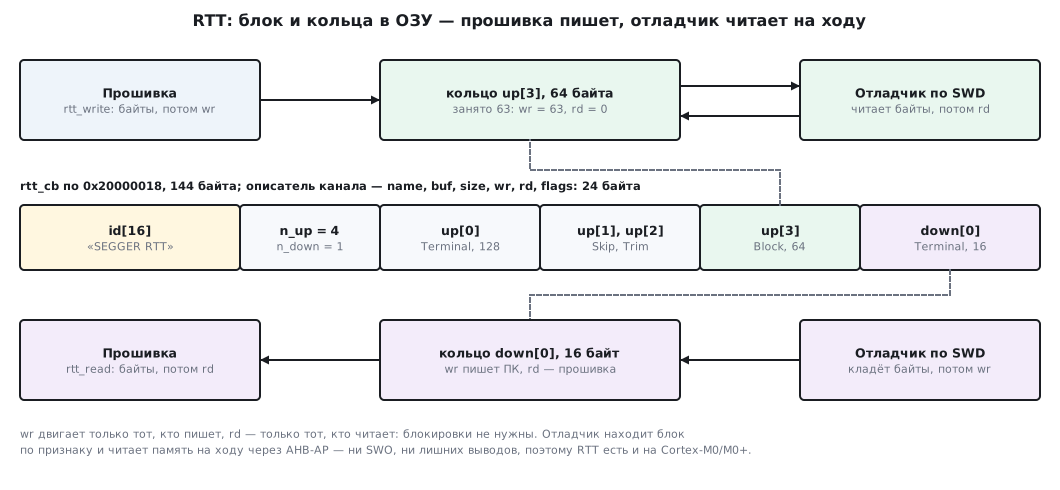
The main rule: the write pointer is moved only by the one who writes, the read pointer only by the one who reads. Each 32‑bit word is changed by one side only, so no locks and no disabling of interrupts between the firmware and the debugger are needed.
21а.2 The control block: byte by byte
A channel descriptor is six words of 4 bytes, 24 bytes:
typedef struct {
    const char *name;                    /* имя канала для ПК, может быть 0 */
    char *buf;                           /* начало кольца */
    uint32_t size;                       /* размер кольца; полезно size - 1 байт */
    volatile uint32_t wr;                /* куда писать следующий байт: пишет только писатель */
    volatile uint32_t rd;                /* откуда читать следующий байт: пишет только читатель */
    uint32_t flags;                      /* биты 1:0 — режим при переполнении */
} rtt_ring_t;
The block is 16 bytes of the identifier, two channel counters of 4 bytes each and the descriptors.
Size: 24 + 24 × (number of channels). The experiment has four "up" channels and one
"down" channel — 144 bytes; one and one is 72 bytes; three and three (the default
according to the comments in SEGGER_RTT_Conf.h) is 168 bytes. The rings themselves
are stored separately, anywhere in RAM.
This is how the block looks in the memory of the F407 in QEMU (the gdb command x/36xw &rtt_cb,
the first six lines):
0x20000018 <rtt_cb>: 0x47474553 0x52205245 0x00005454 0x00000000
0x20000028 <rtt_cb+16>: 0x00000004 0x00000001 0x0800044c 0x200000a8
0x20000038 <rtt_cb+32>: 0x00000080 0x0000002c 0x00000000 0x00000000
0x20000048 <rtt_cb+48>: 0x08000458 0x20000128 0x00000040 0x00000030
0x20000058 <rtt_cb+64>: 0x00000000 0x00000000 0x08000460 0x20000168
0x20000068 <rtt_cb+80>: 0x00000040 0x0000003f 0x00000000 0x00000001
The first 12 bytes are "SEGGER RTT" and zeros; gdb prints them as words, and the bytes in a word go right to left. Then 4 and 1 —
the number of channels. Channel 0: the name in flash (0x0800044c), the ring at 0x200000a8,
size 0x80 = 128, wr = 0x2c = 44, rd = 0, mode 0. The channel name
is in flash — the debugger reads it the same way as RAM.
The start-up order matters: the identifier is written last, when the descriptors are already in memory. Otherwise the debugger may find the block before the ring addresses appear in it:
void rtt_start(void)
{
    static const char id[16] = "SEGGER RTT";   /* константа во флеш, в ОЗУ — только копия в блоке */
    volatile char *dst = rtt_cb.id;
    DMB();                               /* описатели каналов уже в памяти */
    for (unsigned i = 0; i < sizeof(id); i++)
        dst[i] = id[i];                  /* признак — последним: ПК не найдёт полупустой блок */
    DMB();
}
The rtt_init function first erases the whole block, the identifier included:
after a reset without a power cycle, an old block in RAM will not fool the debugger.
21а.3 The ring: one byte is always empty
If wr == rd, the ring is empty. If the writer took all the bytes, wr
would catch up with rd again, and a full ring would be indistinguishable from an empty one. That is why
one byte is never used: a 64-byte ring holds 63.
SEGGER does the same — this is stated in the comment to SizeOfBuffer.
static uint32_t room(uint32_t rd, uint32_t wr, uint32_t size)
{
    return rd > wr ? rd - wr - 1u : size - wr + rd - 1u;   /* один байт не занимаем */
}
The writer copies the bytes and only then publishes the new wr. Between them there is
a DMB barrier: the core will not reorder the pointer write before the data write.
The instruction exists on ARMv6‑M too, and the firmware for Cortex‑M0 was built with it as well:
        while (k--) {
            buf[wr] = (char)p[done++];
            if (++wr == size)
                wr = 0;
        }
    }
    DMB();                               /* сначала данные, потом указатель записи */
    r->wr = wr;
The reader on the computer does the mirror image: it reads wr, takes the bytes from
rd to wr and writes the new rd. The firmware only reads the rd of the "up"
channel. In the "down" channel the roles swap: the computer puts the bytes in and moves
wr, the firmware takes them in rtt_read and writes rd.
21а.4 The experiment in QEMU: the firmware writes, gdb and the reader pick up
The firmware _verify/rtt21a/app21a.c touches neither UART, nor SWO, nor
semihosting. Channel 0 "Terminal" is a 128-byte log, channels 1–3 are one
and the same overflow in three modes (64-byte rings), "down" channel 0 is
input of a 16-byte string. One and the same firmware is built for three QEMU
machines: netduinoplus2 (Cortex‑M4, like F407 and G474), stm32vldiscovery
(Cortex‑M3, like F103) and microbit (Cortex‑M0). The last one is not an STM32
but an nRF51: QEMU 7.2 has no other M0 machine, but the core is the same as in F0,
G0, L0 and C0. In all three, RAM starts at 0x20000000, as in F103,
F407 and G474 according to their headers.
You cannot connect OpenOCD to QEMU: it needs a debug adapter, and QEMU
offers only a GDB port. So the debugger's role is played by gdb and our own reader
rtt_host21a.py, which talks to the same port with m (read
memory) and M (write) packets. First gdb reads the block with x commands:
break rtt_block_wait
x/s rtt_cb.id
x/2dw &rtt_cb.n_up
x/6xw &rtt_cb.up[3]
0x20000018 <rtt_cb>: "SEGGER RTT"
0x20000028 <rtt_cb+16>: 4 1
0x20000078 <rtt_cb+96>: 0x08000468 0x200001a8 0x00000040 0x0000003f
0x20000088 <rtt_cb+112>: 0x00000000 0x00000002
The breakpoint in rtt_block_wait fired on its own: gdb read nothing,
channel 3 in blocking mode filled up to 63 bytes (0x3f) and stopped to wait.
More about this in 21а.5.
Then the reader: it searches for the identifier in the first 8 KB of RAM, parses the descriptors
and every 50 ms picks up what is new from all "up" channels. When it sees
type: in the log, it puts the string ping into the "down" channel. The output on the F407:
search 0x20000000+0x2000: 1 match(es) 0x20000018
control block 0x20000018: up 4, down 1, 144 bytes
  up   0 Terminal buf=0x200000a8 size=128 wr= 44 rd=  0 mode=0
  up   3 Block    buf=0x200001a8 size= 64 wr= 63 rd=  0 mode=2
  down 0 Terminal buf=0x200001e8 size= 16 wr=  0 rd=  0 mode=0
== up 0 Terminal: 97 bytes
hello, RTT
skip 48 trim 63 block 160 of 160
got: ping
bye
The firmware received the string over the "down" channel and answered got: ping. On M3 and M0
the output is the same, the block is also 144 bytes at 0x20000018; only the
ring addresses change.
One difference from a board. QEMU halts the machine when it receives a packet from the debugger, so on every poll the reader halts it, reads and lets it run again. A real debugger reads memory over SWD without halting the core — this is what RTT is designed for.
On a board the same job is done by OpenOCD. According to its manual: `rtt setup
/* Раздел 21а: своя минимальная реализация RTT — управляющий блок и кольца в ОЗУ.
 * Раскладка блока совместима с тем, что ищут отладчики: строка-признак 16 байт,
 * число каналов «вверх» и «вниз», затем описатели каналов по 24 байта. */
#ifndef RTT21A_H
#define RTT21A_H
#include <stdint.h>

#define RTT_N_UP    4u                   /* каналов «вверх»: прошивка -> ПК */
#define RTT_N_DOWN  1u                   /* каналов «вниз»: ПК -> прошивка */

#define RTT_MODE_SKIP   0u               /* не влезает — не писать ничего */
#define RTT_MODE_TRIM   1u               /* не влезает — записать сколько влезет */
#define RTT_MODE_BLOCK  2u               /* не влезает — ждать, пока ПК прочитает */
#define RTT_MODE_MASK   3u

typedef struct {
    const char *name;                    /* имя канала для ПК, может быть 0 */
    char *buf;                           /* начало кольца */
    uint32_t size;                       /* размер кольца; полезно size - 1 байт */
    volatile uint32_t wr;                /* куда писать следующий байт: пишет только писатель */
    volatile uint32_t rd;                /* откуда читать следующий байт: пишет только читатель */
    uint32_t flags;                      /* биты 1:0 — режим при переполнении */
} rtt_ring_t;

typedef struct {
    char id[16];                         /* «SEGGER RTT» и нули: по нему ПК находит блок */
    int32_t n_up;
    int32_t n_down;
    rtt_ring_t up[RTT_N_UP];
    rtt_ring_t down[RTT_N_DOWN];
} rtt_cb_t;

_Static_assert(sizeof(rtt_ring_t) == 24, "descriptor must be 24 bytes");
_Static_assert(sizeof(rtt_cb_t) == 16 + 4 + 4 + 24 * (RTT_N_UP + RTT_N_DOWN), "control block layout");

extern rtt_cb_t rtt_cb;

void rtt_init(void);
void rtt_setup_up(unsigned ch, const char *name, char *buf, uint32_t size, uint32_t mode);
void rtt_setup_down(unsigned ch, const char *name, char *buf, uint32_t size);
void rtt_start(void);
unsigned rtt_write(unsigned ch, const void *data, unsigned n);
unsigned rtt_read(unsigned ch, void *data, unsigned max);
void rtt_block_wait(void);

#endif
/* Раздел 21а: писатель RTT в прошивке. Кольцо «вверх»: wr двигает только прошивка,
 * rd — только ПК; кольцо «вниз» — наоборот. Поэтому ни блокировок, ни запретов
 * прерываний между прошивкой и отладчиком не нужно. Код свой, не SEGGER. */
#include "rtt21a.h"

rtt_cb_t rtt_cb;                         /* в .bss; адрес ПК находит поиском по строке */

#define DMB() __asm volatile("dmb" ::: "memory")

static uint32_t room(uint32_t rd, uint32_t wr, uint32_t size)
{
    return rd > wr ? rd - wr - 1u : size - wr + rd - 1u;   /* один байт не занимаем */
}

void rtt_init(void)
{
    volatile uint8_t *b = (volatile uint8_t *)&rtt_cb;
    for (unsigned i = 0; i < sizeof(rtt_cb); i++)
        b[i] = 0;                        /* первым стирается и признак */
    rtt_cb.n_up = RTT_N_UP;
    rtt_cb.n_down = RTT_N_DOWN;
}

void rtt_setup_up(unsigned ch, const char *name, char *buf, uint32_t size, uint32_t mode)
{
    rtt_ring_t *r = &rtt_cb.up[ch];
    r->name = name;
    r->buf = buf;
    r->size = size;
    r->wr = 0;
    r->rd = 0;
    r->flags = mode & RTT_MODE_MASK;
}

void rtt_setup_down(unsigned ch, const char *name, char *buf, uint32_t size)
{
    rtt_ring_t *r = &rtt_cb.down[ch];
    r->name = name;
    r->buf = buf;
    r->size = size;
    r->wr = 0;
    r->rd = 0;
    r->flags = 0;
}

void rtt_start(void)
{
    static const char id[16] = "SEGGER RTT";   /* константа во флеш, в ОЗУ — только копия в блоке */
    volatile char *dst = rtt_cb.id;
    DMB();                               /* описатели каналов уже в памяти */
    for (unsigned i = 0; i < sizeof(id); i++)
        dst[i] = id[i];                  /* признак — последним: ПК не найдёт полупустой блок */
    DMB();
}

__attribute__((noinline)) void rtt_block_wait(void)
{
    __asm volatile("nop" ::: "memory");  /* ждать, пока ПК сдвинет rd; тут же удобно ставить точку останова */
}

unsigned rtt_write(unsigned ch, const void *data, unsigned n)
{
    rtt_ring_t *r = &rtt_cb.up[ch];
    const uint8_t *p = data;
    char *buf = r->buf;                  /* копии: запись через char * иначе заставит */
    uint32_t size = r->size;             /* перечитывать их на каждом байте */
    uint32_t mode = r->flags & RTT_MODE_MASK;
    uint32_t wr = r->wr;
    unsigned done = 0;

    if (mode != RTT_MODE_BLOCK) {
        uint32_t space = room(r->rd, wr, size);
        if (n > space) {
            if (mode == RTT_MODE_SKIP)
                return 0;                /* пропуск: сообщение не пишется совсем */
            n = space;                   /* обрезка: пишется начало, сколько влезло */
        }
    }
    while (done < n) {
        uint32_t k = room(r->rd, wr, size);
        if (k == 0) {                    /* сюда попадает только режим блокировки */
            DMB();
            r->wr = wr;                  /* отдать ПК то, что уже записано */
            rtt_block_wait();
            continue;
        }
        if (k > n - done)
            k = n - done;
        while (k--) {
            buf[wr] = (char)p[done++];
            if (++wr == size)
                wr = 0;
        }
    }
    DMB();                               /* сначала данные, потом указатель записи */
    r->wr = wr;
    return done;
}

unsigned rtt_read(unsigned ch, void *data, unsigned max)
{
    rtt_ring_t *r = &rtt_cb.down[ch];
    uint8_t *p = data;
    uint32_t rd = r->rd;
    unsigned got = 0;

    while (got < max && rd != r->wr) {
        p[got++] = (uint8_t)r->buf[rd];
        if (++rd == r->size)
            rd = 0;
    }
    DMB();                               /* байты забраны — теперь можно отдать место */
    r->rd = rd;
    return got;
}