 Embedded HandbookApps
21. SWO and ITM debug output
A debug printf over UART (section 16) costs two pins, an adapter
and noticeable transmission time. SWO solves the same task differently: the output goes
over a line that is already connected to the debugger, at a speed tens of times
higher, and it barely slows the program down. This section shows the setup on F103
and F407, what exactly travels over the line — ITM packets byte by byte, — how many
characters per second it really carries and how to use it to measure
the time of code fragments.
Terms used in the documentation
Term Meaning serial wire output (SWO) serial debug output pin instrumentation trace macrocell (ITM) the trace module trace port interface unit (TPIU) the unit that shapes the output stream stimulus port a trace channel trace enable enabling the trace prescaler the speed divider lock access register the access protection register software source packet a channel packet: header and data synchronization packet a sync packet data watchpoint and trace (DWT) the watch unit and cycle counter cycle counter ( CYCCNT)the core clock cycle counter
21.1 What it is
The Cortex‑M3, M4, M7 and M33 cores have a separate trace unit.
The program writes bytes to its register, the unit packs them into a stream and sends it
out through a single pin — SWO. The debugger receives the stream and shows it
in an output window. Cortex‑M0 and M0+ (F0, G0, L0, C0) do not have this unit —
no ITM, no SWO, no DWT->CYCCNT cycle counter: debug output there is
UART or semihosting through the debugger (section 35а).
The key differences from UART:
| UART | SWO | |
|---|---|---|
| pins | 2 (or 1 for transmit only) | 1 — PB3, also JTDO |
| speed | usually up to 115200 baud | 2 MHz and higher |
| adapter | a USB–UART adapter is needed | not needed, works through the debugger |
| without a debugger | works | does not work |
| channels | one stream | 32 independent |
The SWO pin on F1 and F4 is PB3, the same pin that serves as the JTDO line. That is why
it works only when you connect over SWD, not JTAG: in SWD mode
the JTDO line is free and is given to the trace.
21.2 Setup
#define ITM_LAR_KEY   0xC5ACCE55u

void swo_init(void)
{
    /* 1. Разрешить вывод трассировки наружу.
          Заодно это переводит PB3 из режима JTDO в режим SWO. */
    DBGMCU->CR |= DBGMCU_CR_TRACE_IOEN;

    /* 2. Разрешить ядру отладочные функции. */
    CoreDebug->DEMCR |= CoreDebug_DEMCR_TRCENA_Msk;

    /* 3. Снять защиту записи регистров ITM. */
    ITM->LAR = ITM_LAR_KEY;

    /* 4. Делитель и протокол. Делитель кодируется как «значение минус один». */
    TPI->ACPR = (CORE_HZ / SWO_HZ) - 1u;
    TPI->SPPR = 2u;                     /* 2 -> асинхронный NRZ, как у UART */

    /* 5. Включить модуль трассировки и каналы 0 и 1. */
    ITM->TCR = ITM_TCR_ITMENA_Msk
             | ITM_TCR_SYNCENA_Msk
             | (1u << ITM_TCR_TraceBusID_Pos);
    ITM->TER = 3u;                      /* разрешены каналы 0 и 1 */
}
Five steps, and skipping any of them gives silence with no diagnostics. The third one
is especially non-obvious: the ITM registers are protected against accidental writes, and
the protection is removed by writing the fixed value 0xC5ACCE55.
The code is the same for F103 and F407: DBGMCU, CoreDebug, ITM and TPI are parts
of the Cortex‑M core and of the ST debug unit with the same bits. Only the
core frequency differs, and the prescaler is computed from it:
| Divider for 2 MHz | In ACPR |
|
|---|---|---|
| F103, core 72 MHz | 36 | 35 |
| F407, core 168 MHz | 84 | 83 |
21.3 Printing a character
int swo_putchar(int ch)
{
    /* Модуль выключен (его не включили ни прошивка, ни отладчик) — выходим,
       иначе программа зависнет в ожидании готовности. */
    if (((ITM->TCR & ITM_TCR_ITMENA_Msk) == 0u) || ((ITM->TER & 1u) == 0u)) {
        return ch;
    }

    while (ITM->PORT[0].u32 == 0u) { }   /* канал занят предыдущим байтом */
    ITM->PORT[0].u8 = (uint8_t)ch;
    return ch;
}
⚠️ The check for an enabled module is mandatory. Without it, firmware in which nobody enabled the ITM will hang on the very first output: the program will wait forever for the channel to become ready, and nobody will ever make it ready. This is exactly the case of "works on the desk, does not start in the field".
But the check looks at whether the module is enabled, not at whether a debugger is connected. If the firmware enables the module itself (
swo_initfrom 21.2), the check always passes, and without a debugger the bytes simply go out of the pin at SWO speed — the time is wasted. To avoid wasting it in the field, callswo_initonly when a debugger is connected:if (CoreDebug->DHCSR & CoreDebug_DHCSR_C_DEBUGEN_Msk) swo_init();. TheC_DEBUGENbit is set by the debugger; after you disconnect it the bit may stay set until a power-on reset.
Then the output is redirected to printf the same way as for UART —
by overriding fputc in Keil or _write in GCC.
21.4 Receiving on the computer side
In Keil it is the View → Serial Windows → Debug (printf) Viewer window, and the trace
must be enabled in the debugger settings on the Trace tab. In CubeIDE: in the
debug settings, on the debugger tab, enable Serial Wire Viewer and enter the
core frequency, then open the SWV ITM Data Console window, in its settings
tick port 0 (and 1 for the measurements from 21.9) and press the start trace button —
without it the window stays empty. Other IDEs and debuggers have their own utilities.
⚠️ The core frequency in the debugger settings must match the real one. The debugger recovers the stream by knowing the speed, and computes the speed from the core frequency you enter. You clocked the chip up to 72 MHz, but the settings still say 8 — you will see garbage or nothing. The symptom is recognisable: there is output, but it is unreadable.
The second nuance: the SWO speed must divide the core frequency exactly. At 72 MHz good values are: 2 MHz (divider 36), 4 MHz (18), 1 MHz (72). A fractional divider gives a crumbling stream. The debugger also has its own limit on receive speed — look it up in the debugger's description.
21.5 Thirty-two channels
Besides plain text output, ITM has a feature that makes it worth learning: 32 independent channels.
You can split the streams by topic — the state of a state machine into one channel, sensor data into another, errors into a third — and filter them on the computer side without mixing them into one feed. The channel number travels in every packet (21.6), so the separation costs nothing.
Besides manual output, the unit can also produce automatic trace: interrupt entry and exit events, cycle counters. These are already profiling tools — the topic of section 35.
21.6 What travels over the line: ITM packets
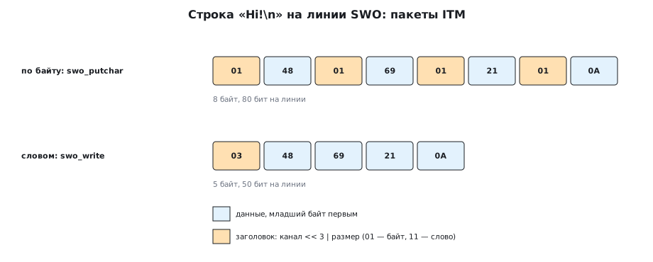
Every write to a channel turns into a packet: a header byte and data. In the header the channel number is shifted three bits to the left, and the low two bits are the size of the write: 01 — byte, 10 — halfword, 11 — word. Data goes least significant byte first. The packet model and an independent decoder give, for the string "Hi!\n":
- byte by byte, as
swo_putcharwrites it: 01 48 01 69 01 21 01 0A — eight bytes, half of them headers; - as one word: 03 48 69 21 0A — five bytes.
Sometimes a sync packet 00 00 00 00 00 80 is inserted into the stream — the receiver uses it
to find the start of packets if it connected in the middle of the stream. It is enabled by the
SYNCENA bit in the setup.
21.7 Throughput
In NRZ mode the SWO line transmits a byte like UART does: start, 8 bits, stop — 10 bit intervals. At 2 MHz that is 200000 bytes per second on the line. Hence:
| Characters per second | A 60-character string | |
|---|---|---|
| UART 115200 | 11520 | 5.21 ms |
| SWO 2 MHz, byte by byte | 100000 | 0.60 ms |
| SWO 2 MHz, as words | 160000 | 0.375 ms |

SWO byte by byte is 8.7 times faster than UART, as words 13.9 times. A write to a channel costs a few cycles while the unit has room; if you print continuously, the program still waits for the line — hence the advice to write in words:
void swo_write(const char *s, uint32_t n)
{
    if ((ITM->TCR & ITM_TCR_ITMENA_Msk) == 0u || (ITM->TER & 1u) == 0u)
        return;
    while (n >= 4u) {
        uint32_t w = (uint32_t)(uint8_t)s[0] | (uint32_t)(uint8_t)s[1] << 8
                   | (uint32_t)(uint8_t)s[2] << 16 | (uint32_t)(uint8_t)s[3] << 24;
        while (ITM->PORT[0].u32 == 0u) { }
        ITM->PORT[0].u32 = w;            /* младший байт уходит первым */
        s += 4;
        n -= 4u;
    }
    while (n--)
        swo_putchar(*s++);
}
21.8 F407: a fast core, the same dividers
At 168 MHz the divider for 2 MHz is 84, and the choice of integer speeds is different: 2 MHz, 4 MHz (42), 6 MHz (28), 8 MHz (21). The frequency in the debugger settings is 168 MHz, not the crystal frequency: a common cause of garbage on the F407, where the PLL clocks the core up to 168 MHz from an 8 MHz crystal.
Both series have a trap with PB3: after reset it is in JTDO mode,
and if the program gives it to GPIO (often to free a pin
on the board), SWO disappears: it is one pin for the two.
21.9 🔧 Measuring time: the cycle counter and channel 1
The DWT->CYCCNT cycle counter (section 35) together with an ITM channel lets you measure
the time of a code fragment without an oscilloscope: clear it, start it, and at the end
send the value as a word to a separate channel so that it does not mix
with the text.
void swo_cycles_begin(void)
{
    DWT->CYCCNT = 0u;
    DWT->CTRL |= DWT_CTRL_CYCCNTENA_Msk;
}
uint32_t t = DWT->CYCCNT;
while (ITM->PORT[1].u32 == 0u) { }
ITM->PORT[1].u32 = t;            /* на линии: 0x0B и четыре байта */
123456 cycles in channel 1 is 0B 40 E2 01 00 on the line: the header of
channel 1 with a word, then the number least significant byte first. The receiver on the
computer shows channel 1 in a separate window or writes it to a file —
handy for collecting statistics over thousands of measurements. The counter needs the same
TRCENA bit as ITM — it is already enabled in swo_init.
21.10 Pitfalls
Nothing is printed. Check in this order: connection over SWD (not JTAG),
DBGMCU_CR_TRACE_IOEN, TRCENA, the unlock key, the enabled channel,
the Trace settings in the debugger.
Garbage instead of text. The core frequency in the debugger settings does not match the real one: on the F407 it is 168 MHz, not 8.
The program hangs without a debugger. The output function has no check that the module is ready.
PB3 is used as GPIO. It is one and the same pin — either the trace or
your peripheral.
It works, but loses characters or slows the program down. You print more than the line can carry: byte by byte it is 100000 characters per second at 2 MHz. Write in words, raise the speed, print less.
It does not work on a cheap debugger. ST‑Link clones often do not support SWO reception at all, although they program and debug fine. Check that your unit can do it before looking for a bug in the code.
Cycle measurements in channel 1 are not visible. The channel is not enabled in TER
(you need 3, not 1) or the receiver shows only channel 0.
21.11 Summary
- SWO gives debug output without an adapter, over a single line —
PB3on F1 and F4, — and an order of magnitude faster than UART, but it works only with a debugger connected. PB3is the same line asJTDO, so you need SWD mode, not JTAG, and you must not give it to GPIO: SWO will disappear.- The setup takes five steps and is the same for F103 and F407;
ACPRholds 35 and 83 for 2 MHz. - The output function must check that the module is enabled — otherwise
a standalone start will hang. And
swo_initis called only if a debugger is connected (theC_DEBUGENbit): otherwise output with no receiver wastes time. - Packets travel over the line: a header with the channel and size, data least significant byte first; "Hi!\n" is 8 bytes byte by byte and 5 as a word.
- 2 MHz gives 100000 characters per second byte by byte, 160000 as words; UART 115200 gives 11520.
- Channel 1 and the cycle counter measure time without an oscilloscope.
Full source code
swo21.c — SWO and ITM on F103 and F407: setup, printing a byte and a word, measuring with the cycle counter.
/* Раздел 21 (обогащение): SWO и ITM на F103 и F407 — настройка, вывод байта и слова,
 * замер времени счётчиком тактов DWT с отправкой в канал 1.
 * Собирается armclang с -include stm32f10x.h (STM32F10X_MD) или stm32f4xx.h (STM32F407xx). */
#include <stdint.h>

#if defined(STM32F10X_MD)
#define CORE_HZ 72000000u
#else
#define CORE_HZ 168000000u
#endif
#define SWO_HZ  2000000u
#define ITM_LAR_KEY   0xC5ACCE55u

void swo_init(void)
{
    /* 1. Разрешить вывод трассировки наружу.
          Заодно это переводит PB3 из режима JTDO в режим SWO. */
    DBGMCU->CR |= DBGMCU_CR_TRACE_IOEN;

    /* 2. Разрешить ядру отладочные функции. */
    CoreDebug->DEMCR |= CoreDebug_DEMCR_TRCENA_Msk;

    /* 3. Снять защиту записи регистров ITM. */
    ITM->LAR = ITM_LAR_KEY;

    /* 4. Делитель и протокол. Делитель кодируется как «значение минус один». */
    TPI->ACPR = (CORE_HZ / SWO_HZ) - 1u;
    TPI->SPPR = 2u;                     /* 2 -> асинхронный NRZ, как у UART */

    /* 5. Включить модуль трассировки и каналы 0 и 1. */
    ITM->TCR = ITM_TCR_ITMENA_Msk
             | ITM_TCR_SYNCENA_Msk
             | (1u << ITM_TCR_TraceBusID_Pos);
    ITM->TER = 3u;                      /* разрешены каналы 0 и 1 */
}

int swo_putchar(int ch)
{
    /* Модуль выключен (его не включили ни прошивка, ни отладчик) — выходим,
       иначе программа зависнет в ожидании готовности. */
    if (((ITM->TCR & ITM_TCR_ITMENA_Msk) == 0u) || ((ITM->TER & 1u) == 0u)) {
        return ch;
    }

    while (ITM->PORT[0].u32 == 0u) { }   /* канал занят предыдущим байтом */
    ITM->PORT[0].u8 = (uint8_t)ch;
    return ch;
}

/* Четыре символа одной записью: пакет из пяти байт вместо восьми. */
void swo_write(const char *s, uint32_t n)
{
    if ((ITM->TCR & ITM_TCR_ITMENA_Msk) == 0u || (ITM->TER & 1u) == 0u)
        return;
    while (n >= 4u) {
        uint32_t w = (uint32_t)(uint8_t)s[0] | (uint32_t)(uint8_t)s[1] << 8
                   | (uint32_t)(uint8_t)s[2] << 16 | (uint32_t)(uint8_t)s[3] << 24;
        while (ITM->PORT[0].u32 == 0u) { }
        ITM->PORT[0].u32 = w;            /* младший байт уходит первым */
        s += 4;
        n -= 4u;
    }
    while (n--)
        swo_putchar(*s++);
}

/* Замер участка кода: счётчик тактов DWT (раздел 35), результат — словом в канал 1. */
void swo_cycles_begin(void)
{
    DWT->CYCCNT = 0u;
    DWT->CTRL |= DWT_CTRL_CYCCNTENA_Msk;
}

void swo_cycles_end(void)
{
    uint32_t t = DWT->CYCCNT;
    if ((ITM->TCR & ITM_TCR_ITMENA_Msk) && (ITM->TER & 2u)) {
        while (ITM->PORT[1].u32 == 0u) { }
        ITM->PORT[1].u32 = t;            /* на линии: 0x0B и четыре байта */
    }
}

/* ── проверка расчётов ────────────────────────────────────────────────── */
_Static_assert(CORE_HZ % SWO_HZ == 0u, "скорость SWO делит частоту ядра нацело");
_Static_assert((CORE_HZ / SWO_HZ) - 1u == (CORE_HZ == 168000000u ? 83u : 35u), "ACPR: 83 на F407, 35 на F103");
_Static_assert(DBGMCU_CR_TRACE_IOEN == (1u << 5), "TRACE_IOEN — бит 5 у обеих серий");
_Static_assert(CoreDebug_DEMCR_TRCENA_Msk == (1u << 24), "TRCENA — бит 24");
_Static_assert(DWT_CTRL_CYCCNTENA_Msk == 1u, "CYCCNTENA — бит 0");
_Static_assert(sizeof(ITM->PORT) / sizeof(ITM->PORT[0]) == 32u, "32 канала");

int main(void)
{
    swo_init();
    swo_cycles_begin();
    swo_write("Hello, SWO!\n", 12u);
    swo_cycles_end();
    for (;;) { }
}
Next: section 21а "RTT: output and input through the debugger without SWO or UART" — output through memory that the debugger reads on the fly, including on Cortex‑M0.