 Embedded HandbookApps
22. External circuitry and indication
There are never enough pins. A BluePill has 37 of them, and half are taken by interfaces — yet you also need eight LEDs, a four-digit display and a keypad. This section is about getting by with few pins: shift registers for output and for input, multiplexed display and a keypad in one timer interrupt — with a model of ghost key presses and a current calculation.
Terms used in the documentation
Term Meaning shift register a register that moves bits one position per clock serial-in parallel-out serial input, parallel output latch / storage register the latch, the output register output enable enabling the outputs daisy chain a chain of chips connected in series multiplexing lighting display digits one at a time common anode / cathode all segments of a digit share the anode / cathode addressable LED an LED with its own controller and address in a chain parallel load ( PL)loading all inputs at once ghosting a false key press in a matrix debouncing suppressing contact bounce
22.1 Expanding outputs: 74HC595
The chip receives bits serially and puts them on eight parallel outputs. Three microcontroller pins turn into eight, and when chips are daisy-chained, into sixteen, twenty-four and so on.
| Pin | Purpose |
|---|---|
SER |
data |
SRCLK |
shift clock |
RCLK |
latch: transfer to the output register |
OE |
output enable (active low) |
SRCLR |
shift register clear |
The key detail is the separate latch. While you shift the bits in, the outputs
do not change: they hold the previous state. A pulse on RCLK sets
everything new at the same time. Without it, a display would show
the intermediate states — flicker and "ghosts".
It is most convenient to connect it over SPI (section 18): the data and the shift clock
are exactly MOSI and SCK, and the latch is toggled with an ordinary GPIO.
void hc595_write(const uint8_t *data, uint8_t count)
{
    LATCH_LOW();
    /* Последняя микросхема в цепочке получает данные первой. */
    for (uint8_t i = count; i > 0u; i--) {
        spi1_xfer(data[i - 1u]);
    }
    while (SPI1->SR & SPI_SR_BSY) { }   /* последний бит должен дойти до регистра */
    LATCH_HIGH();          /* по фронту всё выводится наружу одновременно */
}
The reversed byte order follows from how the chain works: the bits pass
straight through, and the first byte sent is pushed out to the farthest chip.
Waiting for BSY before the latch is mandatory: the receive flag goes up before
the last bit has reached the register, and without the wait you latch a value that has
not been fully shifted (section 18.11).
22.2 Expanding inputs: 74HC165
The mirror task. The chip latches the state of eight inputs and hands them out serially.
| Pin | Purpose |
|---|---|
PL |
load: capture the state of the inputs |
CP |
shift clock |
Q7 |
serial output |
CE |
clock enable, active low: tie it to ground, otherwise there is no shift |
DS |
chain input: the Q7 of the next, farther chip comes here; on the last one it goes to ground |
The sequence: a short PL pulse captures all inputs at the same time,
then eight clocks read them out. Simultaneity matters — otherwise the button state
would be "smeared" over the polling time.
Over SPI this is a read without a transmit: PL is an ordinary output, CP is SCK,
Q7 is MISO:
PL_LOW();              /* захватить все входы разом */
PL_HIGH();
data[i] = spi1_xfer(0xFFu);      /* первой приходит ближняя к микроконтроллеру */
The order is the reverse of the 74HC595: the first byte to arrive is from the chip whose Q7
is connected to the microcontroller.
⚠️
Q7cannot be disconnected — it has no third state, and on a shared SPI bus it drivesMISOall the time, corrupting the replies of other devices. In that caseQ7is connected toMISOthrough a buffer with an enable (74HC125) that is opened only for the time of the read — or the register gets an SPI of its own.
This way one set of three pins serves any number of buttons, and bounce is handled in software exactly as for an ordinary button (section 8).
22.3 The seven-segment display and multiplexing
A four-digit display is 28 segments plus the dots. Connecting each one separately makes no sense; instead the digits are lit one at a time.
The logic: set the segments of the first digit, turn on the first digit, turn it off, set the segments of the second, turn on the second — and so on in a circle. If the cycle repeats fast enough, the eye sees all digits at the same time.
Frequency matters. Below 50 Hz per digit there is visible flicker, especially in peripheral vision and on video. For four digits this means switching at least 200 times a second; usually you take a margin — 1 kHz.
It is convenient to drive the refresh from a timer (section 13): the interrupt switches the digit, the main program only changes the number to display. A timer at 1 kHz gives 250 Hz per digit — five times above the flicker threshold.
Digit segments for a common-cathode display, bit 0 is segment a, bit 6 is g: 3F 06 5B 4F 66 6D 7D 07 7F 6F for the digits 0 to 9. The check compared the table with the shapes of all ten digits. For common anode the numbers are the same, inverted.
static const uint8_t SEG[10] = { 0x3F, 0x06, 0x5B, 0x4F, 0x66, 0x6D, 0x7D, 0x07, 0x7F, 0x6F };
⚠️ Brightness drops in proportion to the number of digits. Each digit is lit only a quarter of the time, so the segment current has to be increased — and you must make sure the pulse current does not exceed what is allowed for the display and for the microcontroller output.
⚠️ Do not forget the current-limiting resistors — one per segment, not one common resistor per digit. A common resistor gives different brightness depending on how many segments are lit.
22.4 🔧 WS2812B addressable LEDs
A strip where each LED is controlled individually over a single wire. Inside each one there is a chip that takes its own 24 bits and passes the rest further down the chain.
The protocol is simple in meaning and strict in timing:
| Duration | |
|---|---|
| bit period | 1.25 µs |
| high level for a zero | 0.4 µs |
| high level for a one | 0.8 µs |
| tolerance | ±150 ns |
| reset pause | at least 50 µs on early revisions, 280 µs on later ones |
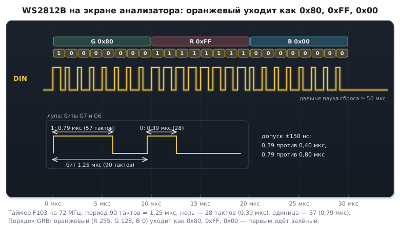
You can toggle the pin in software only with interrupts disabled for the whole transmission: any interrupt will break the timing, and the strip will show random colours. And that is 30 µs without interrupts for every LED. So hardware is used: a timer with DMA, or SPI where each strip bit is encoded with several bits.
The PWM and DMA method is the most reliable. The timer period equals the bit period, and the duty cycle switches between two values:
| Bit period, cycles | Zero | One | |
|---|---|---|---|
| F103, 72 MHz | 90 | 28 | 57 |
| F407, 168 MHz | 210 | 67 | 134 |
#define WS_ARR    (((APB2_TIM_HZ / 1000000u) * WS_PERIOD_NS / 1000u) - 1u)   /* период = ARR + 1 такт */
#define WS_CCR_0  ((APB2_TIM_HZ / 1000000u) * WS_T0H_NS / 1000u)
#define WS_CCR_1  ((APB2_TIM_HZ / 1000000u) * WS_T1H_NS / 1000u)

/* Порядок байтов у WS2812B — зелёный, красный, синий, а не привычный RGB. */
void ws2812_set(uint8_t index, uint8_t r, uint8_t g, uint8_t b)
{
    uint32_t grb = ((uint32_t)g << 16) | ((uint32_t)r << 8) | b;
    uint16_t *p = &ws_buf[index * BITS_PER_LED];

    for (uint8_t i = 0; i < BITS_PER_LED; i++) {
        p[i] = (grb & (1u << (23u - i))) ? WS_CCR_1 : WS_CCR_0;
    }
}
The buffer is expensive: 24 samples of 2 bytes — 48 bytes per LED. A strip of 300 LEDs takes 14400 bytes, more than two thirds of the F103C8 RAM (20 KB).
DMA pours the buffer into the timer compare register, the timer forms the pulses — the processor does not take part at all. At 72 MHz one cycle is about 14 ns, so the accuracy is an order of magnitude better than the required 150 ns.
This is how the transmission for one LED looks on a logic analyser screen — with a zoom on two bits:
Three things people trip over:
The colour order is GRB, not RGB. Green comes first. Mix it up and the colours swap places — this is the most common complaint.
A tail of zeros at the end of the buffer. After the last LED a pause is needed, otherwise the next transmission merges with the previous one: on early WS2812B revisions at least 50 µs, on later ones at least 280 µs. The simplest way is to add 240 zero samples to the buffer: 300 µs is enough for any revision, while forty samples, exactly 50 µs, are good only for old strips. Or the pause is counted by a timer after the DMA finishes.
Power. One LED in white at full brightness draws about 60 mA. A strip of thirty is almost two amperes, which is far beyond what the board can supply. You need a separate supply, a common ground with the microcontroller and a capacitor at the start of the strip.
⚠️ Signal level. The strip is powered from 5 V and formally expects a logic one of at least 3.5 V, while the microcontroller gives 3.3. It often works anyway, but not always and not with every batch of strips — in a product a level shifter is fitted.
22.5 The matrix keypad
Sixteen buttons can be connected with eight pins instead of sixteen: the buttons are placed at the nodes of a four-by-four grid. The program pulls one row to ground at a time and reads the columns.
Two details worth knowing in advance:
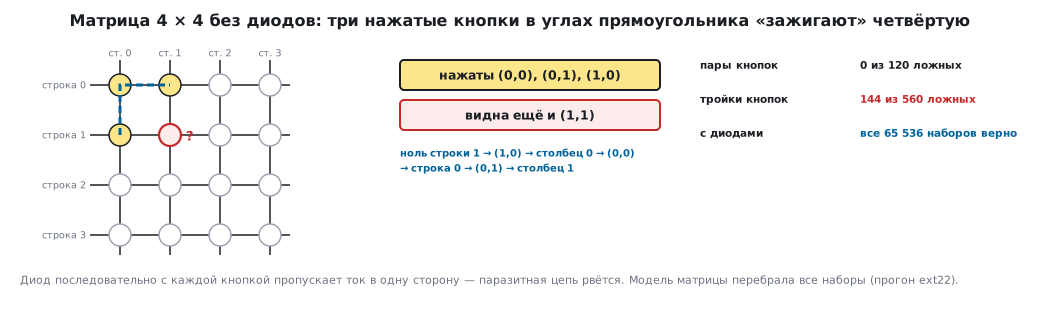
Diodes against ghost presses. When three buttons are pressed at the same time, a parasitic path forms, and the matrix shows a fourth, unpressed one. The 4 × 4 matrix model went through all sets of presses: two buttons never give a ghost press — 0 out of 120 pairs; of the triples, 144 out of 560 give a ghost press — exactly those where the three buttons sit at the corners of a rectangle, and the fourth corner "lights up". Pressed (0,0), (0,1) and (1,0) — and (1,1) is seen as well: the zero from active row 1 goes through (1,0) to column 0, through (0,0) to row 0, through (0,1) to column 1. A diode in series with each button passes current in one direction only, and with diodes all 65536 sets are read correctly. If simultaneous presses are not needed, you can do without diodes.
Inactive rows must be open-drain. If released rows are not let go but are held high, two pressed buttons in one column will short an output driven low to an output driven high.
Pull-ups are mandatory — on the columns, otherwise the inputs "float" (section 8). It is convenient to use the microcontroller's built-in pull-ups.
22.6 Multiplexed display current
A segment is lit a quarter of the time, so an average of 2 mA needs a pulse of 8 mA. The digit 8 with a dot is eight segments at once, and the common pin of the digit then carries 64 mA. The limit for one pin is 25 mA (section 62): the common pin of a digit is never connected to the microcontroller directly — only through a transistor or a switch. The segment pins at 8 mA each are within limits, but the total per package is limited too, so it is also more convenient to drive the segments through a 74HC595.
22.7 🔧 Display and keypad in one interrupt
The display and the keypad need the same rhythm: going through the digits or rows one by one. One timer interrupt at 1 kHz does both jobs: it reads the keypad row pulled low last time, pulls the next one low and outputs the next digit.
void TIM2_IRQHandler(void)
{
    uint8_t out[2];
    TIM2->SR = ~TIM_SR_UIF;
    keypad_scan_row(cur);                                     /* строка cur прижата с прошлого раза */
    cur = (uint8_t)((cur + 1u) & 3u);
    GPIOB->BSRR = (0x000Fu & ~(1u << cur)) | (1u << (cur + 16));   /* отпустить остальные строки, прижать следующую */
    out[0] = SEG[digits[cur]];                                /* сегменты */
    out[1] = (uint8_t)(1u << cur);                            /* ключ разряда */
    hc595_write(out, 2);
}
The bit of row cur in the lower half of BSRR is cleared on purpose: if both set
and reset are written for one pin, the set wins (section 8),
and the row would never be pulled low. The row is read a millisecond after
it was pulled low — the lines have time
to recharge, and the delay costs nothing. Each row is polled
every 4 ms; debouncing is five identical polls in a row, that is 20 ms:
static void keypad_scan_row(uint8_t row)
{
    uint8_t cols = (uint8_t)(~(GPIOB->IDR >> 4) & 0x0Fu);   /* нажатая кнопка тянет столбец к нулю */
    key_raw[row] = cols;
    for (uint8_t c = 0; c < 4u; c++) {
        uint8_t now = (uint8_t)((cols >> c) & 1u);
        if (now != ((key_state[row] >> c) & 1u)) {
            if (++key_cnt[row][c] >= 5u) {                    /* пять опросов подряд — 20 мс */
                key_state[row] ^= (uint8_t)(1u << c);
                key_cnt[row][c] = 0;
            }
        } else {
            key_cnt[row][c] = 0;
        }
    }
}
The timer is set up the same way on F103 and F407, only the prescaler differs:
71 at 72 MHz and 83 at 84 MHz — both give 1 MHz, and ARR 999 gives 1 kHz.
One button, three commands. On top of debouncing, a short, double and long press are told apart by timestamps. The input is the time in milliseconds and the already clean button state, the output is an event:
enum { BTN_NONE, BTN_SHORT, BTN_DOUBLE, BTN_LONG };

#define LONG_MS   800u                            /* держат дольше — «долгое» */
#define DOUBLE_MS 250u                            /* второе нажатие не позже — «двойное» */

uint8_t btn_step(uint32_t now, uint8_t pressed)
{
    if (pressed && !held) {                       /* нажали */
        held = 1;
        t_down = now;
        long_sent = 0;
    } else if (!pressed && held) {                /* отпустили */
        held = 0;
        t_up = now;
        if (long_sent)
            return BTN_NONE;                      /* долгое уже сообщено */
        if (++clicks == 2) {
            clicks = 0;
            return BTN_DOUBLE;
        }
    }
    if (held && !long_sent && now - t_down >= LONG_MS) {
        long_sent = 1;                            /* сообщаем, не дожидаясь отпускания */
        clicks = 0;
        return BTN_LONG;
    }
    if (!held && clicks == 1 && now - t_up >= DOUBLE_MS) {
        clicks = 0;                               /* второго нажатия не было */
        return BTN_SHORT;
    }
    return BTN_NONE;
}
A run with a 4 ms step, as in the interrupt: a press from 100 to 220 ms gives
SHORT at 472 ms; two presses with a 100 ms pause give DOUBLE at the moment of the second
release, at 400 ms; with a 300 ms pause, two SHORT, at 452 and 852 ms;
holding from 100 ms gives LONG already at 900 ms, without waiting for the release.
The double press is paid for with a delay: a short press is reported only
250 ms after the release — before that you do not know whether a second one will come. If
you do not need the double press, the short one can be reported right at the release. And a click
immediately followed by a hold is here simply a long press: in
the run, a press at 100–200 ms and a hold from 300 ms gave a single LONG at
1100 ms, the first click was swallowed.
22.8 Pitfalls
The display shows garbage when the number changes. The latch was raised before BSY
cleared — the outputs got a value that was not fully shifted.
Flicker on video. The frequency per digit is close to 50 Hz. Use 250 Hz and above.
Digits have different brightness. One resistor per digit instead of one resistor per segment: the more segments are lit, the lower the current of each.
A digit output gets hot or the microcontroller resets. The common pin of the digit is connected directly: 64 mA with eight segments. Use a transistor.
An extra button is pressed. Three buttons at the corners of a rectangle without diodes.
A button fires twice. There is no debouncing, or it is shorter than the contact bounce. 20 ms is the usual margin.
WS2812B colours are mixed up. The order is GRB.
22.9 Summary
- Shift registers turn three pins into eight and more:
74HC595for output,74HC165for input. It is more convenient to connect them over SPI; latch only afterBSYclears. - Multiplexed display: a 1 kHz timer gives 250 Hz per digit; an 8 mA pulse for an average of 2 mA; the common pin of a digit goes through a transistor.
- A current-limiting resistor goes on each segment, not one per digit.
- The WS2812B protocol requires ±150 ns accuracy: PWM with DMA, on the F407 it is 210 cycles per bit.
- The WS2812B colour order is GRB; a pause is needed at the end of a transmission: 50 µs on early revisions, 280 µs on later ones; the strip has its own power supply with a common ground.
- A keypad without diodes is wrong on 144 triples out of 560; with diodes — never. The display and the keypad get along in one interrupt.
Full source code
ext22.c — 74HC595 and 74HC165 over SPI, multiplexed display and a keypad in an interrupt.
/* Раздел 22 (обогащение): 74HC595 и 74HC165 через SPI1, динамическая индикация
 * четырёх разрядов в прерывании таймера, опрос клавиатуры 4×4 с антидребезгом.
 * F103 и F407: armclang с -include stm32f10x.h (STM32F10X_MD) или stm32f4xx.h (STM32F407xx). */
#include <stdint.h>

#if defined(STM32F10X_MD)
#define TIM_HZ 72000000u                 /* TIM2 на APB1 ×2 */
#else
#define TIM_HZ 84000000u
#endif
#define SCAN_HZ 1000u                    /* прерываний в секунду: разряд за разрядом */

#define LATCH_LOW()  (GPIOA->BSRR = 1u << (3 + 16))
#define LATCH_HIGH() (GPIOA->BSRR = 1u << 3)
#define PL_LOW()     (GPIOA->BSRR = 1u << (2 + 16))
#define PL_HIGH()    (GPIOA->BSRR = 1u << 2)

uint8_t spi1_xfer(uint8_t data)
{
    while (!(SPI1->SR & SPI_SR_TXE)) { }
    *(volatile uint8_t *)&SPI1->DR = data;
    while (!(SPI1->SR & SPI_SR_RXNE)) { }
    return (uint8_t)SPI1->DR;
}

void hc595_write(const uint8_t *data, uint8_t count)
{
    LATCH_LOW();
    /* Последняя микросхема в цепочке получает данные первой. */
    for (uint8_t i = count; i > 0u; i--) {
        spi1_xfer(data[i - 1u]);
    }
    while (SPI1->SR & SPI_SR_BSY) { }   /* последний бит должен дойти до регистра */
    LATCH_HIGH();          /* по фронту всё выводится наружу одновременно */
}

/* 74HC165: импульс PL защёлкивает входы, затем байты читаются по MISO. */
void hc165_read(uint8_t *data, uint8_t count)
{
    PL_LOW();              /* захватить все входы разом */
    PL_HIGH();
    for (uint8_t i = 0; i < count; i++) {
        data[i] = spi1_xfer(0xFFu);      /* первой приходит ближняя к микроконтроллеру */
    }
}

/* Сегменты gfedcba, общий катод: единица — сегмент горит. */
static const uint8_t SEG[10] = { 0x3F, 0x06, 0x5B, 0x4F, 0x66, 0x6D, 0x7D, 0x07, 0x7F, 0x6F };

static volatile uint8_t digits[4];        /* что показывать: цифры 0–9 */
static uint8_t cur;                       /* какой разряд горит */

void display_set(uint16_t value)
{
    for (int i = 3; i >= 0; i--) {
        digits[i] = (uint8_t)(value % 10u);
        value /= 10u;
    }
}

/* Клавиатура: строки PB0–PB3 — открытый сток, столбцы PB4–PB7 — вход с подтяжкой вверх. */
static uint8_t key_raw[4], key_cnt[4][4], key_state[4];

static void keypad_scan_row(uint8_t row)
{
    uint8_t cols = (uint8_t)(~(GPIOB->IDR >> 4) & 0x0Fu);   /* нажатая кнопка тянет столбец к нулю */
    key_raw[row] = cols;
    for (uint8_t c = 0; c < 4u; c++) {
        uint8_t now = (uint8_t)((cols >> c) & 1u);
        if (now != ((key_state[row] >> c) & 1u)) {
            if (++key_cnt[row][c] >= 5u) {                    /* пять опросов подряд — 20 мс */
                key_state[row] ^= (uint8_t)(1u << c);
                key_cnt[row][c] = 0;
            }
        } else {
            key_cnt[row][c] = 0;
        }
    }
}

/* Прерывание таймера 1 кГц: разряд за разрядом, и заодно одна строка клавиатуры. */
void TIM2_IRQHandler(void)
{
    uint8_t out[2];
    TIM2->SR = ~TIM_SR_UIF;
    keypad_scan_row(cur);                                     /* строка cur прижата с прошлого раза */
    cur = (uint8_t)((cur + 1u) & 3u);
    GPIOB->BSRR = (0x000Fu & ~(1u << cur)) | (1u << (cur + 16));   /* отпустить остальные строки, прижать следующую */
    out[0] = SEG[digits[cur]];                                /* сегменты */
    out[1] = (uint8_t)(1u << cur);                            /* ключ разряда */
    hc595_write(out, 2);
}

void scan_timer_init(void)
{
    RCC->APB1ENR |= RCC_APB1ENR_TIM2EN;
    TIM2->PSC = TIM_HZ / 1000000u - 1u;  /* 1 МГц */
    TIM2->ARR = 1000000u / SCAN_HZ - 1u; /* 1 кГц */
    TIM2->DIER = TIM_DIER_UIE;
    TIM2->CR1 = TIM_CR1_CEN;
    NVIC_EnableIRQ(TIM2_IRQn);
}

/* ── проверка расчётов ────────────────────────────────────────────────── */
_Static_assert(TIM_HZ / 1000000u - 1u == (TIM_HZ == 84000000u ? 83u : 71u), "PSC: 71 на F103, 83 на F407");
_Static_assert(1000000u / SCAN_HZ - 1u == 999u, "ARR 999 — 1 кГц");
_Static_assert(SCAN_HZ / 4u == 250u, "250 Гц на разряд — впятеро выше порога мерцания 50 Гц");
_Static_assert(5u * 4u * 1000u / SCAN_HZ == 20u, "антидребезг: 5 опросов строки по 4 мс — 20 мс");

int main(void)
{
    uint8_t in[2];
    display_set(1234u);
    scan_timer_init();
    hc165_read(in, 2);
    for (;;) { }
}
btn22.c — one button: short, double and long press (22.7).
/* Подраздел 22.7: одна кнопка — короткое, двойное и долгое нажатие.
 * btn_step получает время в миллисекундах и уже отфильтрованное от дребезга состояние
 * (то, что даёт опрос из 22.7 раз в 4 мс) и возвращает событие. Ниже — тест по меткам
 * времени: сценарии прогоняются шагами по 4 мс, как в прерывании таймера. */
#include <stdint.h>
#include <stdio.h>

enum { BTN_NONE, BTN_SHORT, BTN_DOUBLE, BTN_LONG };

#define LONG_MS   800u                            /* держат дольше — «долгое» */
#define DOUBLE_MS 250u                            /* второе нажатие не позже — «двойное» */

static uint8_t held, clicks, long_sent;
static uint32_t t_down, t_up;

uint8_t btn_step(uint32_t now, uint8_t pressed)
{
    if (pressed && !held) {                       /* нажали */
        held = 1;
        t_down = now;
        long_sent = 0;
    } else if (!pressed && held) {                /* отпустили */
        held = 0;
        t_up = now;
        if (long_sent)
            return BTN_NONE;                      /* долгое уже сообщено */
        if (++clicks == 2) {
            clicks = 0;
            return BTN_DOUBLE;
        }
    }
    if (held && !long_sent && now - t_down >= LONG_MS) {
        long_sent = 1;                            /* сообщаем, не дожидаясь отпускания */
        clicks = 0;
        return BTN_LONG;
    }
    if (!held && clicks == 1 && now - t_up >= DOUBLE_MS) {
        clicks = 0;                               /* второго нажатия не было */
        return BTN_SHORT;
    }
    return BTN_NONE;
}

/* ── тест: интервалы «нажата» в миллисекундах, шаг 4 мс ─────────────────── */
struct press { uint32_t from, to; };

static void run(const char *name, const struct press *p, unsigned n)
{
    static const char *const ev[] = {"", "SHORT", "DOUBLE", "LONG"};
    held = clicks = long_sent = 0;
    printf("%s:", name);
    for (uint32_t t = 0; t <= 2000u; t += 4u) {
        uint8_t on = 0;
        for (unsigned i = 0; i < n; i++)
            if (t >= p[i].from && t < p[i].to)
                on = 1;
        uint8_t e = btn_step(t, on);
        if (e != BTN_NONE)
            printf(" %s@%u", ev[e], (unsigned)t);
    }
    printf("\n");
}

int main(void)
{
    static const struct press one[] = {{100, 220}};
    static const struct press two[] = {{100, 200}, {300, 400}};
    static const struct press slow[] = {{100, 200}, {500, 600}};
    static const struct press hold[] = {{100, 1300}};
    static const struct press dhold[] = {{100, 200}, {300, 1300}};
    run("short", one, 1);
    run("double", two, 2);
    run("two_short", slow, 2);
    run("long", hold, 1);
    run("click_then_hold", dhold, 2);
    printf("done=1\n");
    return 0;
}
Next: section 22а "A graphical interface on a display: frame buffer, LTDC, DMA2D and touch" — when a seven-segment display is not enough and you need a screen.