 Embedded HandbookApps
176б. PT100/PT1000 resistance thermometer: ratiometry and 2-, 3- and 4-wire connection
In 96 the temperature was measured by an NTC thermistor, in 104 by a thermocouple. For accurate measurement from −50 to +200 °C, industry uses a platinum resistance thermometer: PT100 or PT1000, 100 or 1000 Ω at 0 °C. Its curve is known in advance and the sensors are interchangeable, but the useful signal is small: tenths of an ohm per degree for the PT100. This section covers how to convert resistance into degrees, how to measure it with the built-in ADC so that the reference does not enter the result, what 10 m leads do, and how many degrees per code are left on the F103 and G474.
Sources: the equation coefficients come from the IEC 60751 standard (well-known
constants; the section was not checked against the text of the standard). The other coefficient sets
and the MAX31865 registers come from the Zephyr v4.4.2 tree (section 34а): the driver
drivers/sensor/maxim/max31865 and the sample samples/shields/lmp90100_evb/rtd.
The F103 (DocID13587) and G474 (DS12288) datasheets come from the Keil packs. All calculations are
the PC model _verify/rtd176c; the conversion code was built with armclang for both
chips and run on the PC over the whole range against the model. The self-heating
coefficient of 0.5 °C/mW, the 10 m cable and the 5 % spread between wires are examples.
Terms used in the documentation
Term Meaning resistance temperature detector (RTD) a resistance thermometer Callendar–Van Dusen equation the equation of the platinum resistance curve ratiometric measurement measuring a ratio, so the reference cancels out reference resistor (RREF) the known resistor in series with the sensor excitation current the current through the sensor 2-, 3-, 4-wire connection connecting the sensor with two, three or four wires lead (wire) resistance the resistance of the connecting wires force / sense leads the current-carrying wires and the measuring wires self-heating the sensor warmed by its own current RTD-to-digital converter a chip that turns RTD resistance into a code fault detection detecting a broken or shorted sensor or wire
176б.1 Platinum and the Callendar–Van Dusen equation
The resistance of platinum rises with temperature almost linearly. More precisely, it follows the Callendar–Van Dusen equation:
R(T) = R0 · (1 + A·T + B·T² + C·(T − 100)·T³),
where R0 is the resistance at 0 °C, A = 3.9083·10⁻³, B = −5.775·10⁻⁷, and C = −4.183·10⁻¹² only below zero; above zero C = 0. The same coefficients work for both PT100 and PT1000: only R0 changes.
| Temperature | PT100, Ω | PT1000, Ω | PT100 slope, Ω/°C |
|---|---|---|---|
| −50 °C | 80.306 | 803.06 | 0.3971 |
| 0 °C | 100.000 | 1000.00 | 0.3908 |
| +100 °C | 138.505 | 1385.05 | — |
| +200 °C | 175.856 | 1758.56 | 0.3677 |
The mean coefficient between 0 and 100 °C is 0.003851 per degree (3850.5 ppm/°C); it is the figure by which sensors are told apart. But a straight line through 0 and 100 °C is not the curve: at +200 °C it reads 3.00 °C low, at −50 °C 1.15 °C low, and at +50 °C 0.37 °C high. The slope falls with temperature: for the PT1000 it is 3.971 Ω/°C at −50 °C and 3.677 Ω/°C at +200 °C.
Three coefficient sets are in use, and they do not agree:
| Source | A | B | Error against IEC 60751 |
|---|---|---|---|
| IEC 60751 | 3.9083·10⁻³ | −5.775·10⁻⁷ | — |
| Zephyr, max31865 driver ("ITS-90") | 3.9080·10⁻³ | −5.870·10⁻⁷ | +0.033 °C at 100 °C, +0.120 °C at 200 °C |
| Zephyr, lmp90100_evb/rtd sample | 3.90802·10⁻³ | −0.58020·10⁻⁶ | +0.015 °C at 100 °C, +0.045 °C at 200 °C, −0.022 °C at −50 °C |
A tenth of a degree at 200 °C is a trifle for a household thermometer and a noticeable amount for metrological verification. Take the coefficients from your own sensor's datasheet, not from the first driver you come across.
176б.2 From resistance to degrees
Above zero the equation is quadratic and is solved by the formula:
T = (−A + √(A² − 4B·(1 − R/R0))) / (2B).
The PC model checked it against the forward curve: the discrepancy is 7.7·10⁻¹³ °C, an exact solution. Below zero the C term makes the equation fourth-degree. The options:
- The same quadratic formula without C. The error at −50 °C is −0.020 °C. Enough for many tasks.
- Newton iterations starting from the quadratic solution. One iteration gives 6.9·10⁻⁸ °C over the whole −50…0 °C interval.
- A polynomial in R. Below zero, the max31865 driver in Zephyr evaluates a fifth-degree polynomial (it refers to the note AN709); against IEC 60751 over −50…0 °C its error is no more than 0.001 °C.
Without floating point, a table with straight lines between points is simpler, as for the NTC in 96.3. The table is stored as R/R0 ratios, so it is shared by PT100 and PT1000:
| Table step | Points over −60…+210 °C | Largest interpolation error |
|---|---|---|
| 5 °C | 55 | 0.0011 °C |
| 10 °C | 28 | 0.0043 °C |
| 30 °C | 10 | 0.0389 °C |
A 10 °C step: 28 numbers of 4 bytes each and an error in thousandths of a degree — smaller than the step of any ADC below. The margin of −60 and +210 °C beyond the edges of the working range is there so that noise near an edge does not throw the reading out of the table.
But the linear formula T = (R − R0) / (R0·A), which the max31865 driver
uses when it is built without newlib, must not be used: −1.47 °C at 100 °C
and −5.90 °C at 200 °C.
176б.3 Ratiometry: the reference cancels out
The direct approach is a 1 mA current source and an ADC that measures the voltage across the sensor relative to its own reference. Then the reference error and the current error enter the result one to one: a reference 1 % below nominal gives +2.59 °C at 0 °C and +4.83 °C at 200 °C.
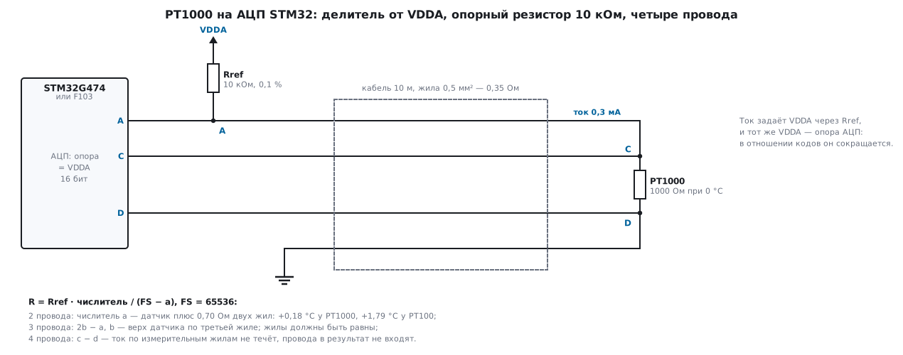
A ratiometric circuit removes both. The sensor sits in a divider with a reference resistor Rref, and the divider is powered from the same voltage that serves as the ADC reference. The code at point A is a ratio of voltages:
a = FS · (R + Rlead) / (Rref + R + Rlead),
and the supply voltage has dropped out of it. Hence R = Rref · a / (FS − a): the code
across Rref shows the current, the code across the sensor shows the voltage, and their ratio is the
resistance. The model went through 2501 temperatures from −50 to +200 °C in
0.1 °C steps at VDDA 3.0, 3.3 and 3.6 V: the codes matched in all 2501 cases
(at 0 °C, 5958 out of 65536). For the NTC the same technique is called a ratiometric
measurement (96.2).
Now the standard is Rref itself, and its error passes into R one to one:
| Rref error | At 0 °C | At 200 °C |
|---|---|---|
| 0.1 % tolerance | 0.256 °C | 0.478 °C |
| TCR 25 ppm/K with the board heating up by 60 K — 0.15 % | 0.384 °C | 0.717 °C |
Calibration removes the tolerance (202.3): the firmware stores the measured value of Rref, not the nominal one (202.5). The drift remains — a low-TCR resistor is cheaper than a voltage reference of the same class (177).
The condition for ratiometry is that the divider is powered from the ADC reference. On the F103
in LQFP48 (BluePill) and LQFP64 packages the VREF+ input is connected to VDDA internally;
in LQFP100 it is brought out separately (pin 21) and is connected to VDDA on the board. On the G474 the VREF+ pin
is shared with VDDA in some packages, and then VREFBUF is not available (DS12288);
in the others VREF+ is connected to VDDA and VREFBUF is left off. A 2.5 V ADC reference
from VREFBUF with a divider powered from 3.3 V is once again an absolute measurement
with the supply error in the result.
176б.4 Two, three, four wires
A 0.5 mm² wire 10 m long is 0.35 Ω. With two wires the sensor is measured together with both wires, 0.70 Ω:
| Sensor | Error at 0 °C | At 200 °C | 0.5 mm² cable per 0.1 °C |
|---|---|---|---|
| PT100 | +1.792 °C | +1.904 °C | 0.56 m |
| PT1000 | +0.179 °C | +0.190 °C | 5.6 m |
For the PT100, two wires are acceptable only on the board; for the PT1000 the error is ten times smaller with the same cable — one of the reasons to choose the PT1000.
Three wires. The third wire runs from the upper terminal of the sensor, and no current flows in it: at point B the ADC sees the voltage of the terminal itself. The difference a − b is the drop across the upper current wire L1, and if the lower wire L2 is the same, its drop is equal to it. Hence the numerator 2b − a: the drop of one wire is subtracted from the voltage across the sensor plus the lower wire. The compensation is exact as long as the wires are equal; if one is 5 % larger than the other, 0.0448 °C remains for the PT100 and 0.0045 °C for the PT1000.
Four wires. Two wires carry the current; the other two, C and D, only pick up the voltage directly at the sensor terminals. The numerator c − d is the voltage across the sensor itself, the denominator FS − a is the current through Rref. The wires do not enter the formula at all: the wire resistance and its spread contribute zero.
| Circuit | Numerator | ADC channels |
|---|---|---|
| 2 wires | a | 1 |
| 3 wires | 2b − a | 2 |
| 4 wires | c − d | 3 |
On the G474 the difference c − d can be taken with one differential channel (15а.4). But this gains nothing: the code unit is twice as large, and the common-mode voltage must, per DS12288, lie within VREF+/2 ± 0.18 V — 1.47…1.83 V at 3.3 V. In our divider the sensor sits at ground, so the common-mode voltage is 0.15 V; the sensor would have to be lifted with a resistor below it. Three single-ended channels are simpler.
176б.5 Step in degrees, self-heating, and when you need an external ADC
The sensor signal is current times slope. More current means a larger signal, but the sensor heats up from its own power I²·R and shows a temperature above that of its surroundings. Below: an ideal current source, 0 °C, a 3.3 V reference; the code unit of a single-ended input is 0.806 mV at 12 bits and 0.0504 mV at 16 bits (oversampling by 256 with a shift of 4, 15а.5), and of a differential input 1.611 and 0.1007 mV. Self-heating is taken at 0.5 °C/mW (an example: the real figure is in the sensor datasheet and depends on the package and the medium).
| Sensor and current | Signal, mV/°C | Power | Self-heating | 12 bits | 16 bits | Diff. 12 bits | Diff. 16 bits |
|---|---|---|---|---|---|---|---|
| PT100, 1 mA | 0.391 | 0.100 mW | 0.0500 °C | 2.061 °C | 0.1288 °C | 4.123 °C | 0.2577 °C |
| PT100, 0.1 mA | 0.039 | 0.001 mW | 0.0005 °C | 20.614 °C | 1.2884 °C | 41.228 °C | 2.5768 °C |
| PT1000, 1 mA | 3.908 | 1.000 mW | 0.5000 °C | 0.206 °C | 0.0129 °C | 0.412 °C | 0.0258 °C |
| PT1000, 0.1 mA | 0.391 | 0.010 mW | 0.0050 °C | 2.061 °C | 0.1288 °C | 4.123 °C | 0.2577 °C |
| PT100, 1 mA, ×10 amplifier | 3.908 | 0.100 mW | 0.0500 °C | 0.206 °C | 0.0129 °C | 0.412 °C | 0.0258 °C |
The conclusion is simple. A PT100 directly on a 12-bit ADC gives two degrees per code; it needs an amplifier (an instrumentation amplifier, section 176) or an external ADC. A PT1000 at 0.1 mA gives the same signal as a PT100 at 1 mA, and heats up ten times less. At 1 mA the PT1000 gives a large signal, but half a degree of self-heating. If an amplifier is fitted, its gain error enters R one to one, like the Rref tolerance.
In a divider powered from VDDA the current is set by Rref. For a PT1000 at 3.3 V and 0 °C:
| Rref | Current | Power | Self-heating | F103, 12 bits | G474, 16 bits |
|---|---|---|---|---|---|
| 2.2 kΩ | 1.031 mA | 1.063 mW | 0.532 °C | 0.29 °C | 0.018 °C |
| 4.7 kΩ | 0.579 mA | 0.335 mW | 0.168 °C | 0.43 °C | 0.027 °C |
| 10 kΩ | 0.300 mA | 0.090 mW | 0.045 °C | 0.76 °C | 0.047 °C |
| 33 kΩ | 0.097 mA | 0.009 mW | 0.005 °C | 2.19 °C | 0.137 °C |
| PT100 and 3.3 kΩ | 0.971 mA | 0.094 mW | 0.047 °C | 2.19 °C | 0.137 °C |
An Rref of 10 kΩ balances self-heating and the G474 step — about 0.05 °C each; this is what the code below uses. Sixteen bits are not accuracy: the extra four bits are real only if the ADC noise dithers them (15а.5, section 165), and the ADC nonlinearity and offset errors do not go anywhere (202).
A dedicated chip. When you need hundredths of a degree, fit an RTD-to-digital converter. The MAX31865 from the Zephyr tree: the resistance code is 15 bits in registers 0x01–0x02, and the least significant bit D0 is the fault flag; R = code / 32768 · Rref. The Zephyr binding recommends an Rref of 400 Ω for the PT100 and 4000 Ω for the PT1000 (citing the datasheet): a step of 0.01221 and 0.1221 Ω, in both cases 0.0312 °C at 0 °C. The configuration register 0x00: bit 7 enables the sensor bias (VBIAS), bit 6 continuous conversion, bit 5 one-shot conversion, bit 4 the three-wire circuit, bits 3:2 the fault detection cycle, bit 1 clears its flags, bit 0 selects the 50 Hz filter instead of 60 Hz. Register 0x07 holds the cause of the fault, 0x03–0x06 the thresholds; for a write, 0x80 is added to the address. After enabling the bias, the driver waits 66 ms before reading. The driver formula R = code / 32768 · Rref is the same ratiometry: the code is a fraction of Rref.
176б.6 Code: from ADC codes to hundredths of a degree
The portable part rtd.c does not touch registers: the input is the 16-bit codes
of points A, B, C, D, the output is the temperature in hundredths of a degree and a status.
On the G474 the 16 bits come from oversampling itself (15а.5); on the F103, from a sum of
16 measurements in software (averaging — 165.8). The parameters:
#define RTD_R0_OHM      1000u       /* PT1000: 1000 Ом при 0 °C */
#define RTD_RREF_MOHM   10000000u   /* опорный резистор 10 кОм, в миллиомах: сюда — измеренное значение */
#define RTD_FS          65536       /* полная шкала: код, соответствующий напряжению опоры */
#define RTD_VDDA_MV     3600u       /* худшее питание делителя — только для проверки тока */
#define RTD_I_MAX_UA    500u        /* больше — самонагрев: 0,5 мА через PT1000 — 0,25 мВт */
#define RTD_DEN_MIN     4096        /* на Rref меньше 1/16 опоры — ток не течёт */
#define RTD_W_SHORT     700000      /* R/R0 ниже 0,70 (около −76 °C) — замыкание */
#define RTD_W_OPEN      2000000     /* R/R0 выше 2,00 (около +266 °C) — обрыв */
#define RTD_W_LEAD      10000       /* провода: не больше 1 % R0 (10 Ом у PT1000) */
/* числитель отношения R/Rref для трёх схем; знаменатель — всегда RTD_FS - a */
#define RTD_NUM_2W(a)        (a)                        /* датчик + оба провода */
#define RTD_NUM_3W(a, b)     (2 * (b) - (a))            /* b — верх датчика по третьему проводу */
#define RTD_NUM_4W(c, d)     ((c) - (d))                /* c, d — измерительные провода */
Build-time checks:
_Static_assert((uint64_t)RTD_VDDA_MV * 1000000u / (RTD_RREF_MOHM + RTD_R0_OHM * 1000u) <= RTD_I_MAX_UA,
               "ток через датчик больше RTD_I_MAX_UA: самонагрев");
_Static_assert((uint64_t)RTD_FS * RTD_RREF_MOHM / (RTD_RREF_MOHM + RTD_R0_OHM * (RTD_W_OPEN / 1000u)) > RTD_DEN_MIN,
               "на пороге обрыва ток должен ещё отличаться от нуля");
_Static_assert(RTD_W_SHORT < 763278 && RTD_W_OPEN > 1795275, "пороги аварии - за краями таблицы");
The first computes the current at the worst-case supply of 3.6 V: 327.3 µA (at 3.3 V, 300.0 µA, 0.090 mW). Get Rref wrong by an order of magnitude — 1 kΩ instead of 10 — and the build stops with a message about self-heating. The second: even at the open-circuit threshold, 54613 code units remain across Rref — more than the threshold of 4096.
Resistance is computed as a ratio in 64-bit integers, temperature from the table of R/R0 in 10 °C steps:
/* R/R0 = (Rref / R0) * num / den, в миллионных, с округлением к ближайшему */
int32_t rtd_w_ppm(int32_t num, int32_t den)
{
    int64_t n = (int64_t)num * RTD_RREF_MOHM * 1000;
    int64_t d = (int64_t)den * RTD_R0_OHM;
    n += (n >= 0 ? d : -d) / 2;
    return (int32_t)(n / d);
}

/* R/R0 -> сотые доли градуса: таблица через 10 °C и прямая между точками */
rtd_status_t rtd_temp(int32_t w, int32_t *t_centi)
{
    if (w < rtd_tab[0] || w > rtd_tab[RTD_N - 1])
        return RTD_RANGE;
    unsigned i = 0;
    while (i < RTD_N - 2 && w >= rtd_tab[i + 1])
        i++;
    int32_t span = rtd_tab[i + 1] - rtd_tab[i];
    *t_centi = (RTD_T0 + RTD_STEP * (int32_t)i) * 100 + (RTD_STEP * 100 * (w - rtd_tab[i]) + span / 2) / span;
    return RTD_OK;
}
Diagnostics come before the conversion, and the order of the checks matters:
rtd_status_t rtd_read(int32_t a, int32_t num, int32_t *t_centi)
{
    int32_t den = RTD_FS - a;                   /* напряжение на Rref — это ток */
    if (den < RTD_DEN_MIN)
        return RTD_OPEN;                        /* тока нет: оборван токовый провод или датчик */
    int32_t w2 = rtd_w_ppm(a, den);             /* датчик вместе с проводами */
    int32_t w = rtd_w_ppm(num, den);
    if (w2 < RTD_W_SHORT)
        return RTD_SHORT;
    if (w2 - w > RTD_W_LEAD || w - w2 > RTD_W_LEAD)
        return RTD_SENSE;                       /* провода «стали» больше 1 % R0: висит измерительный провод */
    if (w > RTD_W_OPEN)
        return RTD_OPEN;
    return rtd_temp(w, t_centi);
}
Current first. When a current wire breaks in the four-wire circuit, the current disappears, c and d are equal, the numerator is zero, and without this check the open circuit would read as a short. Then the two-wire estimate w2 — the sensor together with the wires: if even it is below 0.70 R0 (about −75.8 °C), the sensor itself or the cable is shorted. Then the two estimates are compared: their difference is the wire resistance, and for a PT1000 it is never more than 10 Ω. A broken sense wire leaves the ADC input floating, and the difference goes beyond the limit. Above 2.00 R0 (+266.3 °C) it is an open circuit or a sensor outside its working range.
Run on the PC (rtd_host.c + the same rtd.c, gcc):
- All 955498 R/R0 values in millionths from −50 to +200 °C: the answer matched the integer Python model in all 955498; the largest error against the exact inverse conversion is 0.0092 °C (near −44.92 °C): interpolation plus rounding to a hundredth.
- On a 0.01 °C grid — 25001 points — the code returned exactly the given temperature.
- The full path from the codes, 16 bits, a 10 m cable, 2501 temperatures in 0.1 °C steps, all matched the model: four wires — error ±0.030 °C, three — from −0.060 to +0.070 °C, two — from +0.160 to +0.220 °C (wires plus step). The same four wires with the 12-bit F103 codes — from −0.26 to +0.54 °C.
- Diagnostics, 12 cases: a break in the upper and in the lower current wire — open; a sensor short with four and with two wires and a short at the board — short; a sense wire reading 0 or mid-scale, and a broken third wire — sense wire; −60 and +250 °C — outside the table; +300 °C — open; 0 °C — normal.
176б.7 Pitfalls
Coefficients "as in the driver". The max31865 driver in Zephyr takes A = 3.9080·10⁻³ and B = −5.870·10⁻⁷ — at 200 °C that is +0.120 °C against IEC 60751. Without newlib it computes a straight line altogether: −5.90 °C at 200 °C.
PT100 on two wires. Ten metres of 0.5 mm² wire give +1.79 °C. A PT1000 on the same wires is off by 0.18 °C; beyond that, use three or four wires.
Three-wire circuit with unequal wires. The compensation relies on L1 and L2 being equal. A terminal with poor contact or wires of different cross-section — and the difference goes straight into the result.
The ADC reference is not the one that powers the divider. VREFBUF 2.5 V with the divider powered from
VDDA 3.3 V — there is no ratiometry, and 1 % of the supply is 2.59 °C at 0 °C.
Current "for a large signal". A PT1000 with a 2.2 kΩ Rref heats up by
0.532 °C (at 0.5 °C/mW) — 30 times the G474 step with the same Rref
(0.018 °C).
The _Static_assert on the current catches a wrong resistor value at build time.
An open circuit looks like a short. In the four-wire circuit without current c = d, and the numerator is zero. Check the current (denominator) before the resistance.
Floating sense wire. A broken wire C or D leaves the ADC input unconnected, and it may show a plausible number. The comparison with the two-wire estimate catches this: the wires cannot "weigh" 10 Ω.
Sixteen bits without noise. A sum of identical codes adds no bits: without noise the F103 stays at a step of 0.76 °C.
Differential channel at ground. A common-mode voltage of 0.15 V against the required 1.47…1.83 V — the G474 channel works outside the datasheet conditions.
176б.8 Summary
- The platinum curve is Callendar–Van Dusen: a PT100 is 80.306 Ω at −50 °C, 138.505 at 100 °C, 175.856 at 200 °C. A straight line through 0 and 100 °C is off by 3.00 °C at 200 °C.
- Inverse: the quadratic formula above zero, one Newton iteration below (6.9·10⁻⁸ °C). In integers: an R/R0 table in 10 °C steps, 28 points, 0.0043 °C.
- Ratiometry: the divider is powered from the ADC reference, R = Rref · a / (FS − a). The codes do not
depend on
VDDA(2501 out of 2501); without it, 1 % of the reference is 2.59 °C. Rref becomes the standard: 0.1 % is 0.256 °C at 0 °C. - Wires 10 m × 0.5 mm²: two wires — +1.792 °C for the PT100 and +0.179 °C for the PT1000; three — a residual from the wire spread (5 % gives 0.0448 °C for the PT100); four — zero.
- Step: PT100 at 1 mA on 12 bits — 2.061 °C; PT1000 with a 10 kΩ Rref — 0.76 °C on the F103 and 0.047 °C on the G474 with oversampling, at 0.090 mW in the sensor. MAX31865 — 0.0312 °C.
- Code: a 64-bit ratio, a table, hundredths of a degree; checks for current, short circuit, wires and open circuit; 955498 out of 955498 matched the model, the error is no more than 0.0092 °C; the path from codes with four wires — ±0.030 °C.
Full source code
rtd.h — divider settings and the conversion interface.
/* 176б: термометр сопротивления PT1000 — коды АЦП в сотые доли градуса, в целых числах.
 * Делитель VDDA -> Rref -> точка A -> провод -> датчик -> провод -> земля; опора АЦП — тот же VDDA.
 * Коды — 16 бит: G474 с передискретизацией 256 и сдвигом 4 или сумма 16 измерений F103. */
#ifndef RTD_H
#define RTD_H

#include <stdint.h>

#define RTD_R0_OHM      1000u       /* PT1000: 1000 Ом при 0 °C */
#define RTD_RREF_MOHM   10000000u   /* опорный резистор 10 кОм, в миллиомах: сюда — измеренное значение */
#define RTD_FS          65536       /* полная шкала: код, соответствующий напряжению опоры */
#define RTD_VDDA_MV     3600u       /* худшее питание делителя — только для проверки тока */
#define RTD_I_MAX_UA    500u        /* больше — самонагрев: 0,5 мА через PT1000 — 0,25 мВт */
#define RTD_DEN_MIN     4096        /* на Rref меньше 1/16 опоры — ток не течёт */
#define RTD_W_SHORT     700000      /* R/R0 ниже 0,70 (около −76 °C) — замыкание */
#define RTD_W_OPEN      2000000     /* R/R0 выше 2,00 (около +266 °C) — обрыв */
#define RTD_W_LEAD      10000       /* провода: не больше 1 % R0 (10 Ом у PT1000) */
#define RTD_T0          (-60)       /* таблица: от −60 °C — запас за −50 */
#define RTD_STEP        10          /* через 10 °C */
#define RTD_N           28          /* до +210 °C — запас за +200 */

/* числитель отношения R/Rref для трёх схем; знаменатель — всегда RTD_FS - a */
#define RTD_NUM_2W(a)        (a)                        /* датчик + оба провода */
#define RTD_NUM_3W(a, b)     (2 * (b) - (a))            /* b — верх датчика по третьему проводу */
#define RTD_NUM_4W(c, d)     ((c) - (d))                /* c, d — измерительные провода */

typedef enum { RTD_OK, RTD_OPEN, RTD_SHORT, RTD_SENSE, RTD_RANGE } rtd_status_t;

int32_t rtd_w_ppm(int32_t num, int32_t den);
rtd_status_t rtd_temp(int32_t w, int32_t *t_centi);
rtd_status_t rtd_read(int32_t a, int32_t num, int32_t *t_centi);

#endif
rtd.c — conversion of ADC codes into hundredths of a degree and diagnostics, without floating point.
/* 176б: пересчёт кодов АЦП в температуру PT100/PT1000 и диагностика. Без плавающей точки, без регистров. */
#include "rtd.h"

_Static_assert((uint64_t)RTD_VDDA_MV * 1000000u / (RTD_RREF_MOHM + RTD_R0_OHM * 1000u) <= RTD_I_MAX_UA,
               "ток через датчик больше RTD_I_MAX_UA: самонагрев");
_Static_assert((uint64_t)RTD_FS * RTD_RREF_MOHM / (RTD_RREF_MOHM + RTD_R0_OHM * (RTD_W_OPEN / 1000u)) > RTD_DEN_MIN,
               "на пороге обрыва ток должен ещё отличаться от нуля");
_Static_assert(RTD_W_SHORT < 763278 && RTD_W_OPEN > 1795275, "пороги аварии - за краями таблицы");

/* R/R0 в миллионных долях: W(T) по IEC 60751, A = 3,9083e-3, B = -5,775e-7, C = -4,183e-12 */
static const int32_t rtd_tab[RTD_N] = {
     763278,  803063,  842707,  882217,  921599,  960859, 1000000, 1039025, 1077935, 1116729,
    1155408, 1193971, 1232419, 1270751, 1308968, 1347069, 1385055, 1422925, 1460680, 1498319,
    1535843, 1573251, 1610544, 1647721, 1684783, 1721729, 1758560, 1795275,
};
_Static_assert(sizeof rtd_tab / sizeof rtd_tab[0] == RTD_N, "таблица: -60...+210 °C через 10 °C");

/* R/R0 = (Rref / R0) * num / den, в миллионных, с округлением к ближайшему */
int32_t rtd_w_ppm(int32_t num, int32_t den)
{
    int64_t n = (int64_t)num * RTD_RREF_MOHM * 1000;
    int64_t d = (int64_t)den * RTD_R0_OHM;
    n += (n >= 0 ? d : -d) / 2;
    return (int32_t)(n / d);
}

/* R/R0 -> сотые доли градуса: таблица через 10 °C и прямая между точками */
rtd_status_t rtd_temp(int32_t w, int32_t *t_centi)
{
    if (w < rtd_tab[0] || w > rtd_tab[RTD_N - 1])
        return RTD_RANGE;
    unsigned i = 0;
    while (i < RTD_N - 2 && w >= rtd_tab[i + 1])
        i++;
    int32_t span = rtd_tab[i + 1] - rtd_tab[i];
    *t_centi = (RTD_T0 + RTD_STEP * (int32_t)i) * 100 + (RTD_STEP * 100 * (w - rtd_tab[i]) + span / 2) / span;
    return RTD_OK;
}

/* a — код точки A над токовым проводом; num — RTD_NUM_2W, RTD_NUM_3W или RTD_NUM_4W */
rtd_status_t rtd_read(int32_t a, int32_t num, int32_t *t_centi)
{
    int32_t den = RTD_FS - a;                   /* напряжение на Rref — это ток */
    if (den < RTD_DEN_MIN)
        return RTD_OPEN;                        /* тока нет: оборван токовый провод или датчик */
    int32_t w2 = rtd_w_ppm(a, den);             /* датчик вместе с проводами */
    int32_t w = rtd_w_ppm(num, den);
    if (w2 < RTD_W_SHORT)
        return RTD_SHORT;
    if (w2 - w > RTD_W_LEAD || w - w2 > RTD_W_LEAD)
        return RTD_SENSE;                       /* провода «стали» больше 1 % R0: висит измерительный провод */
    if (w > RTD_W_OPEN)
        return RTD_OPEN;
    return rtd_temp(w, t_centi);
}
Next: section 177 "Voltage references" — what to replace
VDDA and VREFBUF with when their drift eats the error budget.