 Embedded HandbookApps
177. Voltage references: divider, Zener diode, reference IC, drift and noise
Everything the ADC measures, it measures relative to the reference: the code equals
U · 4096 / Uref. So the reference error goes straight into the result — and
no gain calibration of the signal path will remove it if the reference drifts.
This section shows how three ways of getting 2.5 V differ and what the lines
of a voltage reference datasheet mean.
The numbers below come from an ngspice model: a 10 kΩ / 10 kΩ divider, a 2.5 V Zener diode through 2.2 kΩ, and a voltage reference IC with an output resistance of 0.1 Ω, 80 dB of supply rejection and a drift of 20 ppm/°C.
Terms used in the documentation
Term Meaning voltage reference a source of a stable reference voltage initial accuracy the output error of a new part at room temperature temperature drift / tempco (ppm/°C) how the output changes with temperature line regulation output change when the supply changes load regulation output change when the load changes dropout voltage the minimum input headroom above the output output noise (0,1…10 Hz) output noise in the 0.1…10 Hz band long-term drift slow change of the output over time series / shunt reference a three-terminal reference / a two-terminal one used like a Zener bandgap reference a reference based on the silicon bandgap voltage
177.1 Three ways to get 2.5 V
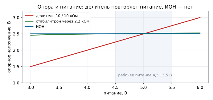
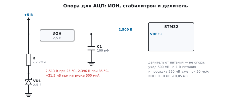
The supply is 5 V, and you need a 2.5 V reference. At 25 °C and with no load all three give almost the same: the divider 2.500 V, the Zener diode 2.513 V, the reference IC 2.500 V. The difference appears as soon as anything at all changes.
The supply changes from 4.5 to 5.5 V:
| Reference | 4.5 V | 5.5 V | Shift per 1 V of supply |
|---|---|---|---|
| divider 10 / 10 kΩ | 2.250 V | 2.750 V | 500 mV |
| Zener diode through 2.2 kΩ | 2.504 V | 2.520 V | 16.0 mV |
| reference IC | 2.500 V | 2.500 V | 0.10 mV |
The divider follows the supply one to one — it is not a reference at all, just a scaled supply. The Zener diode suppresses the shift 31 times, the reference IC 5000 times.
177.2 Load
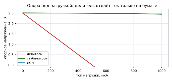
A reference on the VREF+ input of a microcontroller is not "nothing": the input draws current, especially during a conversion. The model, 5 V supply:
| Reference | 50 µA load | 500 µA load |
|---|---|---|
| divider | 2.250 V (−250 mV) | 0 V — collapsed |
| Zener diode | 2.511 V (−1.8 mV) | 2.491 V (−21.5 mV) |
| reference IC | 2.500 V | 2.500 V (−0.05 mV) |
A 10 kΩ divider has an output resistance of 5 kΩ: 50 microamps pull it down by a quarter of a volt, and it simply cannot deliver 500 µA — that much current cannot pass through the upper resistor. The Zener diode does deliver the current, but pays with a shift: its dynamic resistance in the model is tens of ohms. The reference IC has an output resistance of 0.1 Ω, and 500 µA change its output by 50 microvolts.
177.3 Temperature
Heating from 25 to 85 °C:
| Reference | 25 °C | 85 °C | Shift | In codes of a 12-bit ADC |
|---|---|---|---|---|
| divider (ideal resistors) | 2.500 V | 2.500 V | 0 | 0 |
| 2.5 V Zener diode | 2.513 V | 2.396 V | −117 mV | 192 |
| reference IC, 20 ppm/°C | 2.500 V | 2.503 V | +3.0 mV | 4.9 |
Low-voltage Zener diodes have a negative and large temperature coefficient — the model uses a typical −2 mV/°C, and over 60 degrees that adds up to almost five percent. The divider in the model is ideal, but a real one has the TCR of its resistors (section 166.2): a pair with opposite TCR signs of ±100 ppm/°C gives 0.6 % — 25 codes.
Hence a simple rule: a reference must be a reference. A divider is good only where you measure a ratio (a bridge from the same supply), a Zener diode — as a rough threshold or for protection, and anything that must stay accurate over the operating temperature range needs a reference IC.
177.4 What to read in a voltage reference datasheet
- Initial accuracy — the spread from part to part at 25 °C, typically 0.05…0.5 %. It is calibrated once when the product is manufactured.
- Temperature drift in ppm/°C — it cannot be calibrated out: 20 ppm/°C over 60 degrees is 0.12 %, almost 5 codes out of 4096.
- Line and load regulation — the very line and load regulation from the tables above, usually in ppm/V and ppm/mA.
- Noise — usually in microvolts peak-to-peak in the 0.1…10 Hz band; it goes into the noise budget of the signal path (section 165) on a par with the amplifier noise.
- Long-term drift — tens of ppm per 1000 hours, mostly in the first day after soldering; precision instruments get a burn-in.
- Output capacitor — many reference ICs require one, and its value is specified: without it, or with the "wrong" one, the reference oscillates, like an amplifier with a capacitive load from 163.1.
- Dropout — a series reference needs an input 0.2…1 V above its output.
A separate line is the shunt reference (two pins, connected like a Zener diode with a resistor): it is simpler, but the current through it is constant, and the resistor is calculated for the maximum load and the minimum supply.
177.5 The reference inside the microcontroller
STM32 has an internal reference: its voltage (about 1.2 V) is measured
by the same ADC. In most families (F0, F3, F4, G0, G4, L4 and newer)
the factory code of this reference, VREFINT_CAL, is stored in the system memory area,
not in the program Flash. F1 does not have it: the reference is taken at its nominal
1.20 V, and the datasheet spread of 1.16…1.24 V gives about ±3 % on the calculated
supply voltage (section 14.9).
This gives you something unexpectedly useful: by measuring the internal reference, the program
calculates the actual supply voltage, and so it can measure
absolute values even if VREF+ is tied to the supply.
With the factory code, the accuracy of this scheme is tens of millivolts: the internal reference is not meant to be accurate, and it has its own drift. For measurements "in percent" this is enough; for scales or a 0.1 °C thermometer it is not.
177.6 Pitfalls
ADC readings drift together with the supply. The reference is the supply or a divider from it.
In summer the instrument is off by percents. A Zener diode instead of a reference IC: −2 mV/°C is almost 5 % over 60 degrees.
The reference "sagged" when the ADC was turned on. A divider or a reference IC without current headroom: the VREF+ input draws current pulses; you need a capacitor close by and a reference IC that can hold the load.
The reference IC oscillates. There is no capacitor at its output, or its value is wrong — check the documentation, it gives the allowed range.
After soldering the instrument drifted and did not come back. Long-term drift and mechanical stress in the package; calibrate after a burn-in.
The MCU internal reference gives the wrong value. It is used to calculate the supply, not as an accurate reference: it has its own drift and spread, and on F1, without a factory code, another ±3 % from the nominal.
177.7 Summary
- The reference error goes into the result one to one: code =
U · 4096 / Uref. - Shift per 1 V of supply: divider 500 mV, Zener diode 16.0 mV, reference IC 0.10 mV.
- A 500 µA load: the divider collapses, the Zener diode loses 21.5 mV, the reference IC 0.05 mV.
- Heating 25 → 85 °C: Zener diode −117 mV (192 codes), reference IC at 20 ppm/°C — +3.0 mV (4.9 codes).
- In a voltage reference datasheet you read the initial accuracy, the drift in ppm/°C, line and load regulation, the 0.1…10 Hz noise and the output capacitor requirements.
Next: section 178 "Active filters".