 Embedded HandbookApps
178. Active filters: Sallen–Key, order, Q factor, the filter before the ADC
The RC network from section 50.4 is a first-order filter: beyond the cutoff it gives 20 dB per decade and nothing more. When that is not enough — and before an ADC it is not enough almost always — you fit an active filter: the same resistors and capacitors, but with an amplifier that turns them into a resonant circuit without an inductor.
The numbers below come from an ngspice model on the op-amp macromodel from section 164. All the filters are designed for the same cutoff frequency of about 1073 Hz.
Terms used in the documentation
Term Meaning active filter a filter built around an amplifier Sallen–Key topology a filter circuit around a voltage follower multiple feedback (MFB) a filter circuit with several feedback paths cutoff frequency (fc) the frequency where the response starts to fall filter order how steeply the filter falls beyond the cutoff quality factor Q how sharp the response is near the cutoff Butterworth / Bessel / Chebyshev standard response shapes passband ripple / peaking a rise of the response in the passband anti-aliasing filter a filter that prevents aliasing Nyquist frequency half the sampling frequency group delay the delay of a signal through the filter versus frequency
178.1 Why first order is not enough
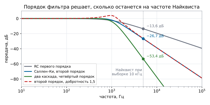
An ADC sampling at 10 kHz "sees" everything above 5 kHz as a false signal at other frequencies — this is aliasing. The job of the filter is to suppress everything above half the sampling frequency. Let us compare at the same cutoff frequency:
| Filter | 1 kHz | 5 kHz — Nyquist | 10 kHz |
|---|---|---|---|
| first-order RC | −2.71 dB | −13.6 dB | −19.4 dB |
| Sallen–Key, second order | −2.03 dB | −26.7 dB | −38.8 dB |
| two Sallen–Key stages, fourth order | −4.06 dB | −53.4 dB | −77.5 dB |
Each order adds 20 dB per decade: the first gives 20, the second 40, the fourth 80. At the Nyquist frequency the difference between the first and the fourth order is 40 decibels, that is, a factor of a hundred in voltage.
The fourth order here is two identical stages, and this is not a Butterworth filter: already at 1 kHz it is −4.06 dB, and −3 dB falls at 923 Hz, not at 1073, as for a true fourth-order Butterworth with the same frequency. For a flat passband the stages are made different — with Q of 0.54 and 1.31 at the same frequency of 1073 Hz: then at 1 kHz it is −1.96 dB, while at 5 and 10 kHz it is almost the same as for the pair of identical stages, −53.5 and −77.6 dB.
178.2 The Sallen–Key circuit
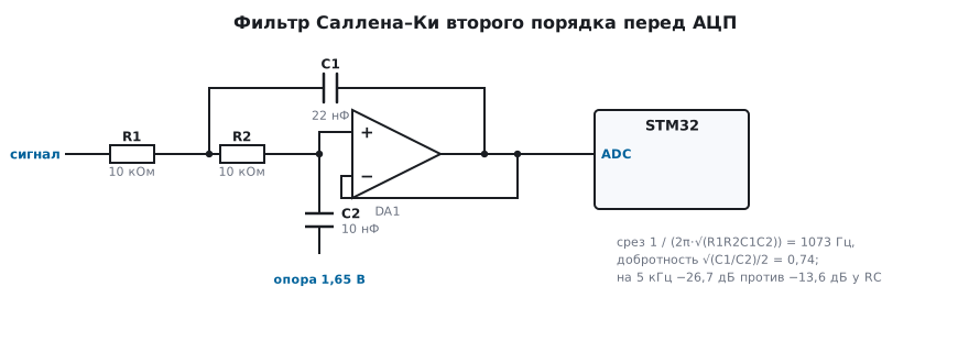
Two resistors and two capacitors around a voltage follower. The cutoff frequency is
1 / (2π · √(R1 · R2 · C1 · C2)), and Q with equal resistors is
√(C1 / C2) / 2. In the model R = 10 kΩ, C1 = 22 nF, C2 = 10 nF: a cutoff of
1073 Hz and Q of 0.74 — a Butterworth response, maximally
flat in the passband.
Why the amplifier is needed at all: capacitor C1 is connected not to ground but to the follower output. The follower "props it up" with its voltage, and the two RC sections stop loading each other — the result is a second order with a controlled Q, not two independent first orders.
178.3 Q factor: peaking and overshoot
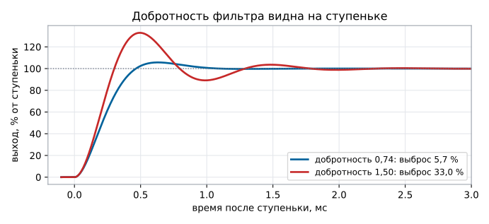
Q is set by the ratio of the capacitors, and it decides how the filter behaves near the cutoff and on a step:
| Q | Response peaking | Step overshoot |
|---|---|---|
| 0.74 (C1 22 nF, C2 10 nF) | +0.04 dB | 5.7 % |
| 1.50 (C1 44.5 nF, C2 4.94 nF) | +4.04 dB | 33.0 % |
With Q of 1.5 the filter lifts everything near the cutoff by four decibels and rings on a step — exactly like an amplifier with a small phase margin (section 163.2). For a measurement path this is bad: interference near the cutoff is amplified, and a fast jump of the signal gives an overshoot that the ADC will see as a real value.
So before an ADC you use a Butterworth (flat passband) or a Bessel (constant group delay, even less overshoot), and a Chebyshev with its peaking only where steepness matters more than the waveform.
178.4 Component tolerance
The same 10 kΩ, but capacitors with a 10 % tolerance in opposite directions — 24.2 and 9 nF:
| Circuit | Response peaking | Attenuation at 5 kHz |
|---|---|---|
| nominal (22 and 10 nF) | +0.04 dB | −26.7 dB |
| 10 % tolerance (24.2 and 9 nF) | +0.29 dB | −26.6 dB |
The attenuation has hardly changed, but Q has risen from 0.74 to 0.82, and peaking has appeared. Hence the rule: in filters use C0G capacitors and 1 % resistors (sections 167.2 and 166.1), not X7R, whose capacitance drifts with both temperature and voltage.
178.5 How many orders you need before the ADC
The reasoning is this: interference at the Nyquist frequency must be suppressed below half the least significant bit. For 12 bits that is 20 · lg(2 · 4096) ≈ 78 dB. In the model at 5 kHz the second order gives 26.7 dB and the fourth 53.4 dB: even the fourth is not enough if the interference can swing full scale.
There are two ways out, and they are usually combined:
- raise the sampling frequency — at 100 kHz instead of 10 kHz the Nyquist frequency moves to 50 kHz, where the same second-order filter already gives more than 60 dB, and the extra samples are averaged (section 165.8);
- add orders — a cascade of two or three Sallen–Key stages, but each stage adds its own tolerances, noise and offset.
A practical combination for slow sensors: an RC section right at the ADC input (section 50.6), a second-order filter in the signal path, and oversampling with averaging in software.
178.6 Pitfalls
The ADC shows a signal that is not there. Aliasing: interference above half the sampling frequency, with no filter, turns into a low-frequency "signal".
A filter was fitted, but the interference stayed. A first order gives only 13.6 dB at Nyquist — that is not enough.
Near the cutoff the signal became larger than in the passband. Q is above 0.707: peaking of +4 dB at Q = 1.5.
After a jump of the signal the ADC catches an overstated value. Overshoot of the step response: 33.0 % at Q = 1.5 against 5.7 % at 0.74.
The cutoff frequency drifted after warming up. X7R capacitors instead of C0G.
A cascade of three stages works worse than two. Each stage adds the amplifier noise and offset (sections 164 and 165); increase the order only as far as needed.
178.7 Summary
- At the Nyquist frequency of 5 kHz: first-order RC −13.6 dB, second-order Sallen–Key −26.7 dB, fourth-order — −53.4 dB.
- Cutoff frequency
1 / (2π · √(R1R2C1C2)), Q√(C1/C2) / 2: 10 kΩ, 22 and 10 nF give 1073 Hz and 0.74. - Q of 1.5 instead of 0.74: peaking of +4.04 dB instead of +0.04 and overshoot of 33.0 % instead of 5.7 %.
- A 10 % capacitor tolerance raises Q to 0.82 and gives +0.29 dB.
- For 12 bits you need about 78 dB at Nyquist — hence oversampling instead of chasing the filter order.
Next: section 179 "Oscillators and nonlinear circuits: relaxation oscillator, Wien bridge, precision rectifier, peak detector".