 Embedded HandbookApps
179. Oscillators and nonlinear circuits: relaxation oscillator, Wien bridge, precision rectifier, peak detector
A microcontroller can output PWM and read an ADC, but sometimes you need a signal or processing that it does not have: a square wave without tying up a timer, a clean sine wave, rectification of a signal of a few millivolts, holding a peak between polls. All four circuits are built on an operational amplifier or a comparator.
The numbers below come from ngspice models on the op-amp macromodel (section 164) and the comparator macromodel (section 175).
Terms used in the documentation
Term Meaning relaxation oscillator an oscillator built on charging and discharging an RC circuit astable multivibrator a free-running square-wave oscillator Wien bridge oscillator a sine oscillator with a Wien bridge in the feedback amplitude stabilisation keeping the oscillation amplitude constant Barkhausen criterion the condition for oscillation to start precision rectifier / superdiode a rectifier with the diode inside op-amp feedback peak detector a circuit that holds the maximum of a signal droop rate how fast the held value decays hold capacitor the capacitor that stores the value
179.1 Relaxation oscillator on a comparator
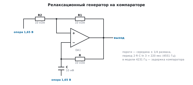
A comparator with hysteresis (section 175.4) plus an RC network from its output to the inverting input — and the circuit starts oscillating by itself: the capacitor charges up to the upper threshold, the comparator switches, the capacitor discharges down to the lower one, and so on round and round.
With hysteresis resistors of 10 and 10 kΩ (the reference is mid-supply) the thresholds
are a quarter of the output swing away from the middle — 0.825 and 2.475 V at 3.3 V,
and the period equals 2 · R · C · ln 3. The model with R = 10 kΩ and C = 10 nF:
| Quantity | Calculation | Model |
|---|---|---|
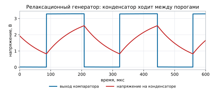
| frequency | 4551 Hz | 4231 Hz |
| swing on the capacitor | ±1/4 of the output swing, 0.825…2.475 V | 0.822…2.559 V |
The 7 % discrepancy is not an error in the formula but the price of a real comparator. Its delay (section 175.2) is unequal here: the output switches down 11.5 µs after crossing the threshold, and up after 0.9 µs. The signal approaches the threshold slowly, and the internal node of the model has to traverse the whole swing to switch down. During those 11.5 µs the capacitor climbs to 2.559 V instead of 2.475, and with that swing the period is 236 µs, as in the model. Besides, the output does not reach the rails (0.008…3.292 V in the model), so the thresholds are slightly different too. Hence the rule: the frequency of such an oscillator is only approximate, and if you need accuracy, use a crystal (section 174) or a microcontroller timer.
179.2 Wien bridge: a sine wave instead of a square wave
A sine wave needs a frequency-selective network in the feedback. A Wien bridge is
two identical RC sections: one in series, the other in parallel. At
the frequency 1 / (2πRC) they attenuate by exactly three times with zero
phase shift, so an amplifier with a gain of exactly 3 closes the loop with
unity gain — the condition for oscillation.
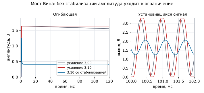
The model with R = 10 kΩ and C = 10 nF (1592 Hz calculated):
| Loop gain | Output swing |
|---|---|
| 3.00 — "exactly enough" | 3.14 V — grew almost to the rails |
| 3.10 — with a margin | 3.28 V — clipped by the rails |
| 3.10 with antiparallel diodes in the feedback | 0.82 V — a stable sine wave |
The key point: a gain of exactly 3 is unattainable. Slightly less, and the oscillations die out; slightly more, and they grow until clipping, and instead of a sine wave you get almost a square wave. So the circuit gets amplitude stabilisation: an element that reduces the gain as the amplitude grows. The classic is an incandescent lamp in the leg to ground: as it heats up, its resistance increases. Modern circuits use a pair of antiparallel diodes shunting part of the feedback resistor: as they open, they reduce it. While the amplitude is small they are closed and the gain is 3.10; as soon as the swing reaches the diode threshold, the gain drops to 3 and the amplitude stops growing.
The frequency in the model with stabilisation is 1582 Hz against the calculated 1592 Hz.
179.3 Precision rectifier: the diode inside the feedback
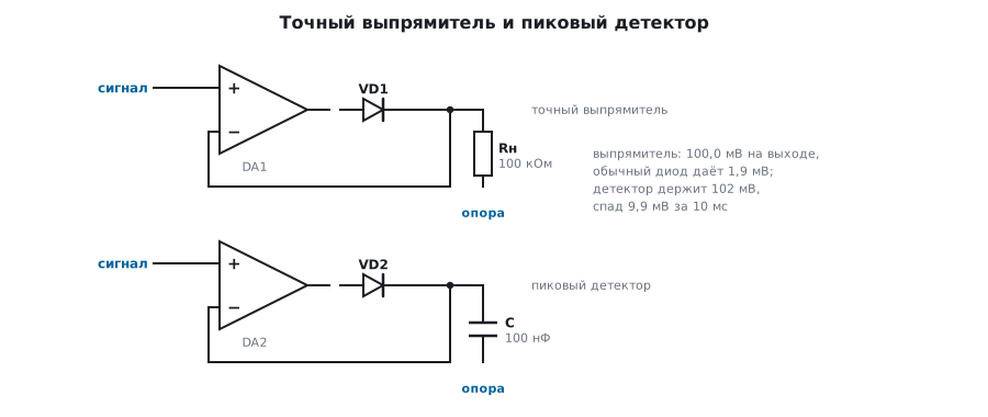
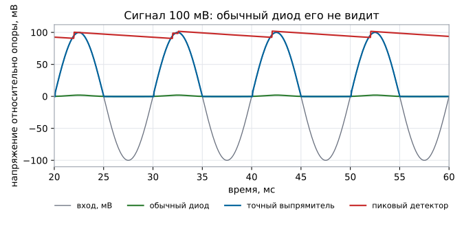
An ordinary diode does not conduct while it has less than half a volt across it, so it simply does not pass signals of a few millivolts. A sine wave with an amplitude of 100 mV:
| Circuit | Output amplitude |
|---|---|
| diode with a 100 kΩ load | 1.9 mV |
| precision rectifier (diode in the op-amp feedback) | 100.0 mV |
The trick is that the diode sits inside the feedback loop: the amplifier raises its output as far as needed to turn the diode on, and the load gets exactly the input voltage. The diode drop is divided by the op-amp gain and disappears.
The price is speed: in the "unwanted" half-wave the op-amp, with no feedback, goes to the lower rail, and at the zero crossing its output has to travel about 2 V. With the model's slew rate of 1 V/µs that is about 2 µs, at 20 kHz 4 % of the period, and the rectifier "cuts off" the crossing. The cure is a two-diode circuit: the second diode closes the feedback in the "unwanted" half-wave, and the op-amp does not saturate; an op-amp with a high slew rate helps too (section 56.2).
179.4 Peak detector
The same precision rectifier, but with a capacitor instead of a resistor: it stores the maximum, and the microcontroller reads it when convenient.
| Quantity | Model |
|---|---|
| held peak with a 100 mV input | 102 mV |
| droop over a 10 ms period (C 100 nF, load 1 MΩ) | 9.9 mV |
The droop is easy to estimate: ΔU = U · t / (R · C). Here the time constant is
100 ms, so over 10 ms a tenth is lost. To reduce the droop, increase the
capacitor and remove the load — read the voltage with a FET-input amplifier
(section 165.4), not with a divider.
The droop is set by the sum of all leakages from the capacitor — the load, the buffer input and
the diode reverse current: dU/dt = I / C. A Schottky diode with a reverse current of 30 µA
(169.3, at 5 V) would discharge 100 nF by 3 V in 10 ms — nothing would be left of a 100 mV peak,
while a silicon signal diode with 2.5 nA would lose only 0.25 mV.
So a peak detector uses a low-leakage silicon diode, not a
Schottky, and you look at the leakage at the highest temperature: at 85 °C the same
silicon diode already has 214 nA — 21 mV in 10 ms.
The flip side of a large capacitor is slow acquisition: the amplifier needs time to charge it to a new peak, and a short pulse may be measured low. The compromise is chosen from the pulse duration and the polling period, and the reset is done with a switch (section 172.6) in parallel with the capacitor.
179.5 Pitfalls
The oscillator frequency is off from the calculation by several percent. Comparator delay and incomplete output swing: 4231 Hz in the model instead of 4551.
The Wien bridge is silent or outputs a square wave. The gain is slightly less or slightly more than three: you need amplitude stabilisation.
The rectifier does not see millivolts. The diode is outside the feedback loop; inside the loop its drop is divided by the gain.
The peak detector reads short pulses low. The capacitor does not have time to charge — use a smaller capacitance or a faster amplifier.
The peak "creeps away" between polls. Droop: U · t / (R · C); the load on the
capacitor must be high-impedance.
An oscillator on an op-amp instead of a comparator heats up and rings. An op-amp used as a comparator comes out of saturation slowly (section 175.1).
179.6 Summary
- Relaxation oscillator: period
2 · R · C · ln 3— 4551 Hz calculated against 4231 Hz in the model; the difference comes from the comparator delay. - Wien bridge at 1592 Hz: a gain of 3.00 reaches a 3.14 V swing, 3.10 goes to clipping at 3.28 V, with antiparallel diodes a stable 0.82 V at 1582 Hz.
- Precision rectifier: 100.0 mV at the output where an ordinary diode gives 1.9 mV.
- Peak detector: holds 102 mV and loses 9.9 mV in 10 ms with a time constant of 100 ms.
Next: section 180 "The analog path around the ADC: sampling capacitor, buffer, multiplexer, driver".