 Embedded HandbookApps
13г. Mechanical encoder with a push button (EC11, KY-040): bounce, timer encoder mode and acceleration
In section 13.7 the timer counted an encoder by itself, in 13.10 a knob changed the brightness of an LED, in 57з.4 an encoder on a shaft measured motor speed. Here it is a user-interface knob: a mechanical encoder with detents and a push button on the shaft, like the EC11 or the KY-040 board. One thing is expected from the knob: as many detents as the person turned, that many steps in the menu, not one more. Contact bounce gets in the way, and so do different knobs (4 or 2 transitions per detent), the power-up order and the counter wrapping over its limit. Here: the quadrature code and the detent, why an edge interrupt counts too much, a state machine on a transition table, TIM4 encoder mode with its input filter, tying the count to the detents, a button with a long press and acceleration on fast turning.
Sources: RM0008 (DocID13902 Rev 17): input with pull-up, IDR is read
every APB2 clock, table 20, p. 160; a timer channel input is a floating
input, table 23, p. 165; encoder mode, counting from 0 to ARR, p. 391;
table 85, counting direction, p. 392; inverting TI1 with the CC1P bit,
p. 393; CKD, p. 403; SMS, p. 407; IC1F and CC1S, p. 414.
DocID13587 Rev 17 (STM32F103x8/xB): PA0, PA1 — TIM2_CH1_ETR,
TIM2_CH2, PA6, PA7 — TIM3_CH1, TIM3_CH2, none of them 5 V tolerant,
p. 29; PA8, PA9 — TIM1_CH1, TIM1_CH2, FT, p. 31; PB6, PB7 —
TIM4_CH1, TIM4_CH2, FT, p. 32; PB8, PB9 — TIM4_CH3, TIM4_CH4,
p. 33; maximum input voltage and injected current, tables 6 and 7, p. 37;
injection should be avoided, p. 61; VIL, VIH, the RPU pull-up,
table 35, p. 62. The project has no documents on the EC11 or the KY-040:
the number of transitions per detent, the contact state in a detent and
the bounce are model assumptions, not manufacturer data. All numbers come
from the _verify/enc13e run: a Python 3.11 model of the knob, the RC
network, the input filter and the timer counter feeds a stream into the
same enc13e.c code, built by arm-none-eabi-gcc 12.2.1 for the Cortex-M3
and run in QEMU 7.2; the firmware is built by armclang 6.24.
What it is called in the documentation
Original Meaning rotary encoder, incremental encoder encoder that counts steps, not absolute angle quadrature signals A and B two signals shifted by a quarter period detent a fixed resting position of the knob contact bounce a contact opening and closing several times when it switches encoder interface mode ( SMS= 011)counting both edges of both channels input filter ( ICxF),f_SAMPLING, Nsampling rate and how many samples in a row clock division ( CKD),t_DTSdivider of the filter sampling clock auto-reload ( ARR)counting limit: the counter runs from 0 to ARRstate transition table table of "was — became" pairs acceleration the step grows when the knob is turned fast long press holding the button for a long time five-volt tolerant (FT) a pin that withstands 5 V
13г.1 Quadrature code: how many transitions per detent
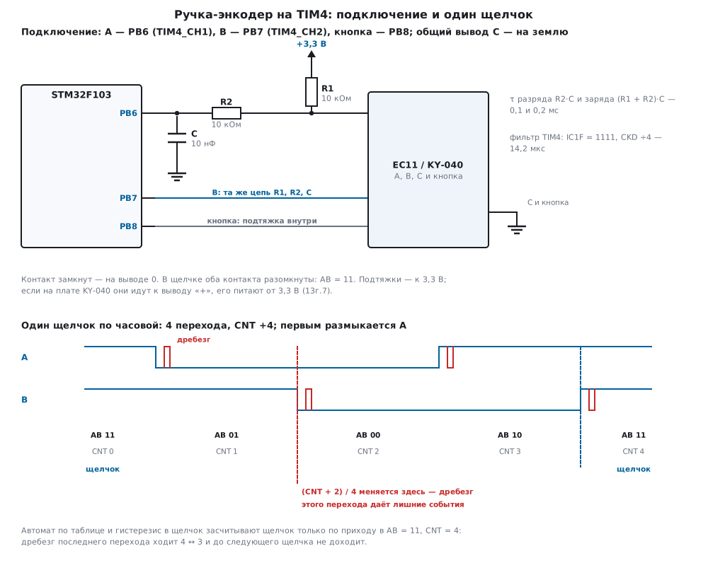
The knob has two contacts, A and B, and a common pin C to ground. When it turns they close and open shifted by a quarter cycle, so exactly one bit changes between two neighbouring states. In the model, clockwise AB goes 11 → 01 → 00 → 10 → 11: A opens first. Counter-clockwise is the same circle backwards. The direction is the order in which A and B change, not the level of either of them. Which contact of your knob is first depends on the wiring; if it counts the wrong way, see 13г.7.
How many transitions fall on one detent is up to the knob. Some have a
full cycle per detent — four transitions, both contacts open in the
detent, AB = 11. Some have half a cycle — two transitions, and the
detents rest at 11 and 00 in turn. The project has no documents on the
EC11 and KY-040, so you check with your own knob: one detent and the
difference of the timer CNT — 4 or 2. In the model a half-cycle knob
turned 30 detents forward and 10 back brought CNT to 40, that is 2 per
detent, and a full-cycle knob on the same turns brought it to 80.
| Knob | Divided by | Made: net / total | CNT at the end |
Counted: net / total |
|---|---|---|---|---|
| 2 transitions per detent | 4 | 20 / 40 | 40 | 10 / 20 — every other one |
| 2 transitions per detent | 2 | 20 / 40 | 40 | 20 / 40 |
| 4 transitions per detent | 2 | 20 / 40 | 80 | 40 / 80 — twice as many |
"Net" is detents with a sign, "total" is all detents both ways. The
divider in the code is per, 4 or 2, and it must match the knob.
13г.2 Bounce: why an edge interrupt counts too much
A contact bounces when it closes and opens. In the model after every transition there are 0 to 6 returns to the old level: a pause of 20…400 us, a return of 2…250 us, the whole burst no longer than 2 ms. While the contact is closed, sliding also gives sparks — openings of 1…12 us, one per 10 ms on average. These are model assumptions, not manufacturer data.
The simplest code is an interrupt on the falling edge of A and reading B: B = 1 — a step forward, B = 0 — back. Without bounce that is one step per detent. With bounce every rebound is another falling edge. On a falling A going forward they add steps, and on a rising A (a rebound back to zero) they add steps backwards, because B is already 0 there. In the model we turned 60 detents forward, 45 back and 30 forward — net 45, total 135:
| Method | Interrupts | Counted |
|---|---|---|
| falling A, read B | 1746 | −70 instead of 45 |
| the same through RC 10 nF | 471 | −1 instead of 45 |
| state machine on a table, 1 ms polling (13г.3) | — | 45, total 135 |
| TIM4 in encoder mode (13г.4, 13г.5) | — | 45, total 135 |
There were 7190 edges on the lines for 540 real ones (135 × 4). The interrupt also loads the CPU: 1746 handler entries for 135 detents.
RC network. The circuit is the same as for the button in 50.7: a
pull-up R1 to 3.3 V at the contact, R2 in series to the pin and a
capacitor on the pin. The contact closes — the capacitor discharges
through R2; it opens — it charges through R1 + R2. The F103 input
thresholds are VIL = 0.28·(VDD − 2) + 0.8 and VIH = 0.41·(VDD − 2) +
1.3 (table 35, p. 62), at 3.3 V that is 1.164 and 1.833 V; the model
switches the Schmitt trigger exactly at these limits.
| R1, R2, C | Discharge τ | Charge τ | Fall delay | Rise delay |
|---|---|---|---|---|
| 10 kOhm, 10 kOhm, 10 nF | 100 us | 200 us | 104.2 us | 162.1 us |
| internal pull-up (40 kOhm), 10 kOhm, 10 nF | 100 us | 500 us | 104.2 us | 405.4 us |
| 10 kOhm, 10 kOhm, 100 nF | 1000 us | 2000 us | 1042.1 us | 1621.4 us |
The internal pull-up is 30…50 kOhm, typically 40 (table 35, p. 62): charging is 2.5 times slower. The 10 nF network does not pass a single rebound shorter than its delay: an opening of 160 us did not pass, of 170 us it did; a closing of 100 us did not pass, of 110 us it did. Longer rebounds pass, which is why 10 nF was not enough for the interrupt.
A capacitor 10 times larger kills all the bounce of the model, but it also delays the transitions by 1…1.6 ms. Three runs of 200 detents each:
| Rate | No RC | 10 nF | 100 nF |
|---|---|---|---|
| 50 detents/s: edges (2400 real) | 16 392 | 8744 | 2400 |
| 50 detents/s: interrupt exact | 0 of 3 | 0 of 3 | 3 of 3 |
| 100 detents/s: interrupt / state machine exact | 0 / 1 of 3 | 0 / 1 of 3 | 3 / 3 of 3 |
| 200 detents/s: edges (2400 real) | 16 186 | 8578 | 2030 |
| 200 detents/s: timer exact | 0 of 3 | 0 of 3 | 0 of 3 |
At 200 detents per second the 100 nF network ate real transitions — fewer edges than made. The capacitance is chosen between the length of the bounce and the step between the A and B transitions. With the timer and the state machine the counting needs no RC (13г.3, 13г.4), and the 10 nF on the schematic is there for sparks and noise on the wire; 100 nF — if counting by interrupt.
13г.3 State machine on a transition table
A software solution without parts: read AB once per 1 ms and look from which state to which it moved. There are sixteen "was — became" pairs, and the table has an answer for each: a step forward, back or nothing.
/* индекс — (прошлое AB << 2) | новое AB; +1 — шаг по часовой (11 → 01 → 00 → 10 → 11), −1 — против,
 * 0 — стоим на месте или перескочили через состояние (оба бита сразу: направление неизвестно) */
static const int8_t qtab[16] = {
     0, -1, +1,  0,     /* из 00: в 00, 01, 10, 11 */
    +1,  0,  0, -1,     /* из 01 */
    -1,  0,  0, +1,     /* из 10 */
     0, +1, -1,  0,     /* из 11 */
};
Bounce does no harm to the table: a rebound there and back is +1 and −1. The steps accumulate, and a detent counts only in the resting state — AB = 11 (for a 2-transition knob also 00). The step count is reset there too, and the state machine is tied to the detents again:
/* щелчок засчитывается только в состоянии покоя, и там же сбрасывается счёт шагов: дребезг даёт +1 −1
 * и до покоя не доходит, а один пропущенный шаг (перескок) округление ещё прощает */
int enc_qdec_step(enc_qdec_t *q, uint8_t ab)
{
    int ev = 0, half = q->per / 2;
    ab &= 3u;
    q->acc = (int8_t)(q->acc + qtab[(q->ab << 2) | ab]);
    q->ab = ab;
    if (ab == ENC_REST || (q->per == 2u && ab == 0u)) {
        ev = q->acc >= 0 ? (q->acc + half) / q->per : -((-q->acc + half) / q->per);
        q->acc = 0;
    }
    return ev;
}
A skip — both bits changed between two polls — counts as zero in the table: the direction is unknown. Rounding forgives one such skip per detent: at rest 2 of 4 will have accumulated, and that is still a detent. Two skips are not forgiven.
How much 1 ms polling withstands the model checked at a constant rate: 100 detents forward and 100 back, three runs per rate with bounce and one without it. Revolutions assume 20 detents per revolution (an assumption).
| Detents/s | Rev/s | Step between transitions | With bounce: state machine | With bounce: timer | Without bounce: state machine |
|---|---|---|---|---|---|
| 20 | 1 | 12.5 ms | 3 of 3 | 3 of 3 | |
| 50 | 2.5 | 5 ms | 3 of 3 | 3 of 3 | |
| 80 | 4 | 3.125 ms | 3 of 3 | 3 of 3 | |
| 100 | 5 | 2.5 ms | 0 of 3 | 3 of 3 | |
| 120 | 6 | 2.083 ms | 0 of 3 | 3 of 3 | |
| 150 | 7.5 | 1.667 ms | 0 of 3 | 0 of 3 | 200 of 200 |
| 300 | 15 | 0.833 ms | 0 of 3 | 0 of 3 | 200 of 200 |
| 400 | 20 | 0.625 ms | 100 of 200 |
With bounce up to 2 ms the state machine is exact up to 80 detents per second: the step between transitions must hold both the bounce and one more polling period. Without bounce it lasts up to 300 detents per second, at 400 it gets half of them (at an even rate the polling hits the same phases). Above 120 detents per second the timer errs as well: if the step is shorter than the bounce, one contact is still jumping when the other switches, and the AB sequence on the pins is itself wrong. Such a turn — 6 revolutions per second — is rare for a user-interface knob.
13г.4 Timer encoder mode: registers, filter, ARR
The timer counts the transitions by itself, by table 85 (p. 392): both edges of both channels, the direction by the level of the other channel. The inputs are only TI1 and TI2, that is channels 1 and 2 of one timer (p. 391):
| Timer | A (CH1) | B (CH2) | 5 V tolerant |
|---|---|---|---|
| TIM2 | PA0 | PA1 | no (p. 29) |
| TIM3 | PA6 | PA7 | no (p. 29) |
| TIM4 | PB6 | PB7 | yes (p. 32) |
| TIM1 | PA8 | PA9 | yes (p. 31) |
Here it is TIM4 on PB6 and PB7: the pins withstand 5 V (13г.7). The setup:
static void enc_hw_init(void)
{
    RCC->APB2ENR |= RCC_APB2ENR_IOPBEN;
    RCC->APB1ENR |= RCC_APB1ENR_TIM4EN;
    /* PB6, PB7 — вход без подтяжки (0100): подтяжки на плате; PB8 — вход с подтяжкой (1000 и ODR8 = 1) */
    GPIOB->CRL = (GPIOB->CRL & 0x00FFFFFFu) | 0x44000000u;
    GPIOB->CRH = (GPIOB->CRH & ~0xFu) | 0x8u;
    GPIOB->BSRR = 1u << 8;
    /* TI1 и TI2 — входы каналов 1 и 2, фильтр 1111: 8 выборок на f_DTS / 32 */
    TIM4->CCMR1 = TIM_CCMR1_CC1S_0 | TIM_CCMR1_CC2S_0 | TIM_CCMR1_IC1F | TIM_CCMR1_IC2F;
    TIM4->CCER = 0;                                     /* CC1P = CC2P = 0; CC1P = 1 — счёт в обратную сторону */
    TIM4->SMCR = TIM_SMCR_SMS_1 | TIM_SMCR_SMS_0;       /* 011: оба фронта обоих каналов */
    TIM4->ARR = 0xFFFFu;
    TIM4->CR1 = TIM_CR1_CKD_1 | TIM_CR1_CEN;            /* f_DTS = 72 / 4 = 18 МГц: 8 / 562,5 кГц = 14,2 мкс */
}
CC1S = CC2S = 01 — the channels became inputs TI1 and TI2 (p. 414).
SMS = 011 — counting on both edges of both channels (p. 407); 001 and
010 would count on one channel, 2 per cycle. A timer channel input by
table 23 (p. 165) is a floating input; our pull-ups are on the board.
Input filter. IC1F sets the sampling rate and N — how many samples
in a row with the new level are needed for a transition to pass
(p. 414). The longest is 1111: f_DTS / 32 and N = 8. CKD divides the
filter clock by 1, 2 or 4 (p. 403). The TIM4 clock is 72 MHz, with CKD
= /4 f_DTS = 18 MHz, a sample every 1.78 us. A pulse shorter than 7
samples (12.44 us) never passes, one longer than 8 (14.22 us) always
does; in between the phase decides: in the model a 12.5 us pulse passed
at 7 of 200 sampling phases, a 14 us one at 176.
The same turn, 40 detents there and 40 back, with different filters:
IC1F, CKD |
Sample | N-sample window | Edges at the input | Edges to the counter | Counted, net / total |
|---|---|---|---|---|---|
| 0000, /1 | 0.0139 us | 0.01 us | 4106 | 4106 | −1 / 79 |
| 0011, /1 | 0.0139 us | 0.11 us | 4106 | 4106 | −1 / 79 |
| 1111, /1 | 0.4444 us | 3.56 us | 4106 | 3616 | −1 / 79 |
| 1111, /4 | 1.7778 us | 14.22 us | 4106 | 2030 | 0 / 80 |
Made: 0 and 80. Without the long filter the timer lost a detent, and the culprit is not bounce but a coincidence: an 11.47 us spark on B fell on a rebound of A, and the sequence on the pins went round the circle the other way — −3 instead of +1. The 14.2 us filter removed all 995 sparks of the model: the longest is 11.99 us, shorter than 12.44. There were 898 rebounds, and most of them are longer than the filter: the quadrature counting itself cancels them, +1 and −1 in place. Against bounce lasting milliseconds this gives almost nothing, against short sparks and noise on the wire — everything.
ARR and wrapping through 0. The counter runs from 0 to ARR and over
the edge (p. 391). With ARR = 0xFFFF the signed difference of readings
(int16_t)(uint16_t)(cnt − last) is correct across 0 as well (13.10). But
sometimes ARR is set for a menu: 12 items of 4 transitions — ARR = 47,
and CNT itself goes round 0…47. Then the difference must be taken
modulo 48:
/* разность показаний по модулю ARR + 1, к ближайшему; щелчок — когда позиция ушла от прошлого щелчка
 * на целый щелчок: гистерезис в щелчок, дребезг на любом переходе событий не плодит */
int enc_tim_step(enc_tim_t *e, uint16_t cnt)
{
    int32_t d, top = e->top ? e->top : 65536;
    int ev = 0;
    d = (int32_t)cnt - (int32_t)e->last;
    if (d > top / 2)
        d -= top;
    else if (d < -top / 2)
        d += top;
    e->last = cnt;
    e->pos += d;
    while (e->pos - e->ref >= e->per) {
        e->ref += e->per;
        ev++;
    }
    while (e->pos - e->ref <= -(int32_t)e->per) {
        e->ref -= e->per;
        ev--;
    }
    return ev;
}
In the model with ARR = 47 the knob went 5 detents back from zero, then
20 forward and 3 back: net 12, total 28, CNT at the end is 0. The
modulo-48 difference gave 12 and 28. The int16_t difference gave net 0
and 58 events: it takes the 0 → 47 transition for a step of +47.
13г.5 Dividing by 4 and tying to the detents
In 13.10 the brightness level is (counts + 2) / 4: the level boundary
lies between detents, and bounce at a detent does not jerk the level.
But the boundary lies exactly on the second transition of the detent,
01 → 00 (figure), and it bounces like all the others. For brightness a
one-level flicker in the middle of a turn is invisible; for a menu it is
an extra event, for acceleration a short interval between events. In the
model, on the same 135 detents as in 13г.2, rounding gave 165 events —
30 extra, through RC 10 nF — 145.
enc_tim_step does it differently: a detent counts when the position has
moved a whole detent, 4 counts, away from the previous detent. That is a
hysteresis one detent wide: the detent counts on arrival at the next one,
and the bounce of the last transition goes 4 ↔ 3 and does not reach the
next boundary. The same 135 detents — exactly 135 events.
Tying at start-up. The hysteresis works if the detent count matches
the detent. In the model TIM4 was enabled before the pull-ups rose: A and
B rose from zero, A crossed the threshold after 180 us, B after 260 us,
and CNT counted 00 → 10 → 11 — two steps, CNT = 2. The detents now
sit at 2, 6, 10… — halfway between the counts.
| Start-up | Made: net / total | Hysteresis | Rounding | State machine |
|---|---|---|---|---|
| position from zero | 20 / 60 | 21 / 59 | 21 / 69 | 20 / 60 |
| position from the phase on the pins | 20 / 60 | 20 / 60 | 20 / 68 | 20 / 60 |
The cure is to start the position not from zero but from the phase read
on the pins when the lines have settled. The firmware waits 5 ms — 25 RC
time constants of 0.2 ms — and only then reads CNT and IDR:
/* CNT в момент запуска может стоять не на щелчке: подтяжки поднимали линии, ручку держали между
 * щелчками. Поэтому позиция начинается с фазы, прочитанной на выводах, а не с нуля */
void enc_tim_init(enc_tim_t *e, uint16_t cnt, uint8_t ab, uint8_t per, uint16_t arr)
{
    e->last = cnt;
    e->top = (uint16_t)(arr + 1u);                      /* ARR = 0xFFFF → 0: полный круг 65536 */
    e->per = per;
    e->pos = enc_phase(ab) % per;
    if (e->pos > per / 2)
        e->pos -= per;                                  /* к ближайшему щелчку: фаза 3 — это −1 */
    e->ref = 0;
}
The state machine needs no tying at start-up: it resets the step count at every rest and does not carry a half-detent error. Rounding, even with a correct start-up, gave 8 extra events because of the bounce on the middle transition.
IDR is updated every APB2 clock (p. 160), and the firmware reads A and B
directly from PB6 and PB7 while they work as timer inputs. The same read
in the SysTick handler also drives the state machine — as a cross-check:
tim_sum and qdec_sum must match.
13г.6 The button and acceleration
The button on the shaft is an ordinary contact to ground, the
debouncing is the same as in 2ж.5: the level is trusted when it has not
changed for 20 ms, a long press is 800 ms. One thing is added: if the
knob was turned with the button held, on release you get not "short" but
ENC_KEY_TURN, and the long press does not fire — a press with a turn
becomes a separate gesture. In the firmware the held button switches the
knob from the value to the menu item. In the model — 120 presses with
bounce up to 8 ms on press and release, 12 of them with a turn of 3
detents: all 72 short, 36 long and 12 turning presses were recognised.
Acceleration. A value from 0 to 1000 one per detent is 1000 detents, 50 revolutions at 20 detents per revolution. The step is made to depend on how often the detents come. The thresholds are counted from revolutions: slower than one revolution per second is fine adjustment, a detent less often than once per 50 ms, step 1; faster than two revolutions per second — more often than once per 25 ms, and the whole range should fit into 2 revolutions, 40 detents: step 1000 / 40 = 25. In between — step 5. A change of direction and the first detent after a pause go back to step 1, otherwise an overshoot cannot be corrected.
/* шаг по времени с прошлого щелчка в ту же сторону; смена направления или пауза — снова шаг 1 */
int32_t enc_accel(enc_accel_t *a, int ev, uint32_t now_ms)
{
    int8_t dir;
    int32_t step = 1;
    if (ev == 0)
        return 0;
    dir = ev > 0 ? 1 : -1;
    if (dir == a->dir) {
        uint32_t dt = now_ms - a->t_last;
        if (dt < ENC_ACC_FAST_MS)
            step = ENC_STEP_FAST;
        else if (dt < ENC_ACC_SLOW_MS)
            step = ENC_STEP_MID;
    }
    a->t_last = now_ms;
    a->dir = dir;
    return ev * step;
}
| How it was turned | Detents | Time | Value | Without acceleration |
|---|---|---|---|---|
| 28 fast (15…18 ms per detent), a pause, 30 slow (90…140 ms) | 58 | 4.163 s | 706 | 58 |
| 73 fast (15…18 ms) | 73 | 1.218 s | 1000 — the limit | 73 |
| 60 medium (30…45 ms) | 60 | 2.291 s | 296 | 60 |
| 60 slow (60…120 ms) | 60 | 5.434 s | 60 | 60 |
The fast run gave 1 + 27 × 25 = 676, the slow one added 30 one by one: the value 706 was reached in 58 detents instead of 706. The medium rate is 1 + 59 × 5 = 296, the slow one is not accelerated at all. The firmware measures the interval by polling once per 1 ms, and detents of 15…18 ms were seen in the model from 14 ms: near the 25 ms threshold that does not matter, but a threshold closer to the hand's rate would give a step of 5 one time and 25 the next. The thresholds are a choice for 20 detents per revolution and a range of 1000; for another knob and another range they are recalculated the same way.
13г.7 Pitfalls
The timer does not count at all. Channels of the wrong pair: B on PB8
is TIM4_CH3 (p. 33), or A on TIM2 and B on TIM3. Encoder mode takes only
TI1 and TI2 of its own timer (p. 391). In the model the second input sat
at 1: 250 edges of A reached the counter, and CNT, by table 85, went
back and forth and ended at 0 — not one detent of 20.
Counting the wrong way. A and B are swapped, or the other contact
opens first. In the model instead of 20 detents forward — −20, CNT =
65456, that is 65536 − 80. CC1P = 1, the inversion of TI1 (p. 393),
does the same. Fixed by swapping the wires, by the CC1P bit or by a
sign in the code.
Every other detent, or two per detent. The wrong divider: a 2-transition knob divided by 4 — 10 detents of 20, a 4-transition knob divided by 2 — 40 (13г.1).
The menu flickers to the neighbouring item in the middle of a turn.
The level is computed by rounding (CNT + 2) / 4: the bounce of the
middle transition gives 30 extra events per 135 detents (13г.5).
After power-up the detents sit halfway. The timer was started before
the pull-ups rose: CNT = 2, a detent is lost on reversal. The position
should start from the phase on the pins after a pause (13г.5).
The menu jumps over the edge. ARR = 47 and an int16_t
difference: 0 → 47 is +47, 58 events instead of 28 (13г.4).
KY-040 with pull-ups to 5 V on a 3.3 V input. If the board's pull-ups go to its "+" pin and that is on 5 V, then A and B are at 5 V too. Pins that are not 5 V tolerant (PA0, PA1, PA6, PA7 — p. 29) withstand no more than 4.0 V at the input (table 6, p. 37); the current will flow through the protection diode into the 3.3 V supply, with a 10 kOhm pull-up up to (5 − 3.3) / 10 kOhm = 0.17 mA. Table 7 allows ±5 mA, but such injection should be avoided in normal operation (p. 61). FT pins (PB6, PB7) withstand 5 V, but only with the internal pull-up switched off (the note to table 35, p. 62) — that is why the firmware configures PB6 and PB7 as floating inputs, 0100. The simplest is to power the KY-040 from 3.3 V.
A fast turn loses detents. The bounce is longer than the step between transitions: with bounce up to 2 ms the timer is exact up to 120 detents per second, the state machine with 1 ms polling up to 80 (13г.3). RC 100 nF at 200 detents per second eats real transitions too (13г.2).
The filter is set to the maximum, and the bounce is still there. The longest filter at 72 MHz is 14.2 us, bounce is milliseconds. The filter removes sparks and noise, bounce is removed by the quadrature counting (13г.4).
13г.8 Summary
- Quadrature code: clockwise AB 11 → 01 → 00 → 10 → 11, one bit per
transition. Knobs have 4 or 2 transitions per detent — one detent and
the difference of
CNTwill tell; the wrong divider gives 10 detents of 20 or 40. - An interrupt on falling A reading B gave −70 instead of 45 and 1746 interrupts on 135 detents with bounce; RC 10 nF (τ 0.1 and 0.2 ms) — −1; RC 100 nF kills all the bounce of the model but eats transitions at 200 detents per second.
- The state machine on a table of 16 transitions with a detent only at rest AB = 11 counts exactly; polling once per 1 ms withstands 80 detents per second with bounce up to 2 ms and 300 without bounce.
- TIM4:
CC1S=CC2S= 01,SMS= 011,IC1F= 1111 andCKD= /4 — a 14.2 us filter: it removed all 995 sparks, without it 1 detent of 80 was lost; exact up to 120 detents per second with bounce up to 2 ms. - An encoder only on CH1 and CH2 of one timer; TIM4 on PB6, PB7 and TIM1 on PA8, PA9 withstand 5 V, TIM2 and TIM3 on PA0, PA1, PA6, PA7 do not.
ARRother than 0xFFFF — the difference moduloARR+ 1: 12 and 28 instead of 0 and 58.- A detent by a hysteresis of a whole detent from the previous one: 135
events for 135 detents against 165 with rounding; the start-up position
from the phase on the pins, otherwise after the pull-ups
CNT= 2 and a detent is lost on reversal. - The button: 20 ms and 800 ms, a press with a turn separately; all 120 presses recognised. Acceleration: 50 and 25 ms, steps 1, 5 and 25 — 706 in 58 detents, the whole range of 1000 in 1.218 s.
Full sources
enc13e.h — types, the acceleration and button thresholds, the functions of the state machine, CNT counting, acceleration and the button.
/* enc13e.h — раздел 13г: механический энкодер с кнопкой (EC11, KY-040) без регистров микроконтроллера.
 * Автомат по таблице переходов (опрос выводов), счёт щелчков по CNT таймера в режиме энкодера,
 * ускорение и кнопка. Один и тот же код собирается в прошивку fw13e.c (armclang) и в стенд bench13e.c
 * (arm-none-eabi-gcc, QEMU). AB — два бита: A — старший (канал TI1), B — младший (TI2); 1 — контакт разомкнут. */
#ifndef ENC13E_H
#define ENC13E_H
#include <stdint.h>

#define ENC_REST           3u       /* в щелчке оба контакта разомкнуты: A = B = 1 */
#define ENC_ACC_SLOW_MS    50u      /* щелчки реже — шаг 1 (меньше 1 оборота в секунду при 20 щелчках) */
#define ENC_ACC_FAST_MS    25u      /* чаще — шаг ENC_STEP_FAST (больше 2 оборотов в секунду) */
#define ENC_STEP_MID       5u
#define ENC_STEP_FAST      25u      /* 1000 / 40: весь ход за 2 оборота по 20 щелчков */
#define ENC_VMAX           1000u
#define ENC_KEY_STABLE_MS  20u      /* антидребезг кнопки: уровень не менялся 20 мс */
#define ENC_KEY_LONG_MS    800u

/* ── автомат по таблице переходов: опрос AB ─────────────────────────── */
typedef struct {
    uint8_t ab;                     /* прошлое состояние AB */
    uint8_t per;                    /* переходов на щелчок: 4 или 2 */
    int8_t acc;                     /* шаги со времени последнего щелчка */
} enc_qdec_t;

void enc_qdec_init(enc_qdec_t *q, uint8_t ab, uint8_t per);
int enc_qdec_step(enc_qdec_t *q, uint8_t ab);           /* +1, −1 — щелчок; 0 — нет */

/* ── счётчик таймера: щелчки по CNT ───────────────────────────────────── */
typedef struct {
    uint16_t last;                  /* прошлое показание CNT */
    uint16_t top;                   /* ARR + 1 */
    uint8_t per;
    int32_t pos;                    /* отсчёты с начала, со знаком */
    int32_t ref;                    /* отсчёт последнего щелчка */
} enc_tim_t;

int enc_phase(uint8_t ab);                              /* AB → фаза 0…3 по часовой стрелке */
void enc_tim_init(enc_tim_t *e, uint16_t cnt, uint8_t ab, uint8_t per, uint16_t arr);
int enc_tim_step(enc_tim_t *e, uint16_t cnt);           /* щелчков со знаком с прошлого вызова */

/* ── ускорение: шаг растёт, когда щелчки идут часто ──────────────────── */
typedef struct {
    uint32_t t_last;
    int8_t dir;                     /* 0 — щелчков ещё не было */
} enc_accel_t;

int32_t enc_accel(enc_accel_t *a, int ev, uint32_t now_ms);

/* ── кнопка: антидребезг, короткое и долгое нажатие, нажатие с поворотом ─ */
enum { ENC_KEY_NONE = 0, ENC_KEY_SHORT, ENC_KEY_LONG, ENC_KEY_TURN };

typedef struct {
    uint8_t raw, stable, long_sent, turned;
    uint32_t t_change, t_down;
} enc_key_t;

int enc_key_step(enc_key_t *k, int pressed, int turned, uint32_t now_ms);

#endif
enc13e.c — the transition table, detents from CNT with hysteresis and modulo ARR + 1, acceleration, the button.
/* enc13e.c — раздел 13г: автомат по таблице переходов, щелчки по CNT таймера, ускорение и кнопка.
 * Микроконтроллера не знает: на вход — AB, CNT и время в миллисекундах. */
#include "enc13e.h"

/* индекс — (прошлое AB << 2) | новое AB; +1 — шаг по часовой (11 → 01 → 00 → 10 → 11), −1 — против,
 * 0 — стоим на месте или перескочили через состояние (оба бита сразу: направление неизвестно) */
static const int8_t qtab[16] = {
     0, -1, +1,  0,     /* из 00: в 00, 01, 10, 11 */
    +1,  0,  0, -1,     /* из 01 */
    -1,  0,  0, +1,     /* из 10 */
     0, +1, -1,  0,     /* из 11 */
};

void enc_qdec_init(enc_qdec_t *q, uint8_t ab, uint8_t per)
{
    q->ab = ab & 3u;
    q->per = per;
    q->acc = 0;
}

/* щелчок засчитывается только в состоянии покоя, и там же сбрасывается счёт шагов: дребезг даёт +1 −1
 * и до покоя не доходит, а один пропущенный шаг (перескок) округление ещё прощает */
int enc_qdec_step(enc_qdec_t *q, uint8_t ab)
{
    int ev = 0, half = q->per / 2;
    ab &= 3u;
    q->acc = (int8_t)(q->acc + qtab[(q->ab << 2) | ab]);
    q->ab = ab;
    if (ab == ENC_REST || (q->per == 2u && ab == 0u)) {
        ev = q->acc >= 0 ? (q->acc + half) / q->per : -((-q->acc + half) / q->per);
        q->acc = 0;
    }
    return ev;
}

int enc_phase(uint8_t ab)
{
    static const uint8_t ph[4] = {2, 1, 3, 0};          /* AB 00, 01, 10, 11 → фаза */
    return ph[ab & 3u];
}

/* CNT в момент запуска может стоять не на щелчке: подтяжки поднимали линии, ручку держали между
 * щелчками. Поэтому позиция начинается с фазы, прочитанной на выводах, а не с нуля */
void enc_tim_init(enc_tim_t *e, uint16_t cnt, uint8_t ab, uint8_t per, uint16_t arr)
{
    e->last = cnt;
    e->top = (uint16_t)(arr + 1u);                      /* ARR = 0xFFFF → 0: полный круг 65536 */
    e->per = per;
    e->pos = enc_phase(ab) % per;
    if (e->pos > per / 2)
        e->pos -= per;                                  /* к ближайшему щелчку: фаза 3 — это −1 */
    e->ref = 0;
}

/* разность показаний по модулю ARR + 1, к ближайшему; щелчок — когда позиция ушла от прошлого щелчка
 * на целый щелчок: гистерезис в щелчок, дребезг на любом переходе событий не плодит */
int enc_tim_step(enc_tim_t *e, uint16_t cnt)
{
    int32_t d, top = e->top ? e->top : 65536;
    int ev = 0;
    d = (int32_t)cnt - (int32_t)e->last;
    if (d > top / 2)
        d -= top;
    else if (d < -top / 2)
        d += top;
    e->last = cnt;
    e->pos += d;
    while (e->pos - e->ref >= e->per) {
        e->ref += e->per;
        ev++;
    }
    while (e->pos - e->ref <= -(int32_t)e->per) {
        e->ref -= e->per;
        ev--;
    }
    return ev;
}

/* шаг по времени с прошлого щелчка в ту же сторону; смена направления или пауза — снова шаг 1 */
int32_t enc_accel(enc_accel_t *a, int ev, uint32_t now_ms)
{
    int8_t dir;
    int32_t step = 1;
    if (ev == 0)
        return 0;
    dir = ev > 0 ? 1 : -1;
    if (dir == a->dir) {
        uint32_t dt = now_ms - a->t_last;
        if (dt < ENC_ACC_FAST_MS)
            step = ENC_STEP_FAST;
        else if (dt < ENC_ACC_SLOW_MS)
            step = ENC_STEP_MID;
    }
    a->t_last = now_ms;
    a->dir = dir;
    return ev * step;
}

/* звать раз в 1 мс; turned — был щелчок в этот вызов */
int enc_key_step(enc_key_t *k, int pressed, int turned, uint32_t now_ms)
{
    uint8_t r = pressed ? 1u : 0u;
    if (k->stable && turned)
        k->turned = 1u;                                 /* крутили с нажатой кнопкой */
    if (r != k->raw) {                                  /* дребезг или настоящее изменение — ждём */
        k->raw = r;
        k->t_change = now_ms;
        return ENC_KEY_NONE;
    }
    if (r != k->stable && now_ms - k->t_change >= ENC_KEY_STABLE_MS) {
        k->stable = r;
        if (r) {
            k->t_down = now_ms;
            k->long_sent = k->turned = 0u;
            return ENC_KEY_NONE;
        }
        if (k->turned)
            return ENC_KEY_TURN;                        /* нажатие с поворотом — не короткое */
        return k->long_sent ? ENC_KEY_NONE : ENC_KEY_SHORT;
    }
    if (k->stable && !k->long_sent && !k->turned && now_ms - k->t_down >= ENC_KEY_LONG_MS) {
        k->long_sent = 1u;
        return ENC_KEY_LONG;
    }
    return ENC_KEY_NONE;
}
fw13e.c — STM32F103 firmware: TIM4 in encoder mode on PB6 and PB7, the button on PB8, everything in SysTick once per 1 ms.
/* fw13e.c — раздел 13г: ручка-энкодер с кнопкой на STM32F103 (BluePill), 72 МГц, такт TIM4 — 72 МГц.
 * TIM4 в режиме энкодера: PB6 — A (TIM4_CH1), PB7 — B (TIM4_CH2), оба с допуском 5 В. На плате у каждой
 * линии подтяжка 10 кОм к 3,3 В, 10 кОм последовательно к выводу и 10 нФ на землю. Кнопка — PB8 на землю,
 * подтяжка внутри. SysTick раз в 1 мс: щелчки по CNT, тот же счёт автоматом по выводам (для сверки),
 * ускорение, кнопка. Отпущенная кнопка — ручка меняет value (0…1000) с ускорением; нажатая — пункт меню
 * по одному. Тактирование до 72 МГц — SystemInit (раздел 6). */
#include "stm32f10x.h"
#include "enc13e.h"

#define CPU_HZ   72000000u
#define PER      4u                                     /* переходов на щелчок: проверить своей ручкой */

static enc_tim_t et;
static enc_qdec_t eq;
static enc_accel_t ea;
static enc_key_t ek;
volatile uint32_t ms;
volatile int32_t value, menu, tim_sum, qdec_sum;        /* tim_sum ≠ qdec_sum — что-то не так с линиями */
volatile uint32_t key_short, key_long, key_turn;

static uint8_t read_ab(void)
{
    uint32_t idr = GPIOB->IDR;
    return (uint8_t)((((idr >> 6) & 1u) << 1) | ((idr >> 7) & 1u));
}

static void delay_ms(uint32_t n)
{
    uint32_t t0 = DWT->CYCCNT;
    while (DWT->CYCCNT - t0 < n * (CPU_HZ / 1000u)) {
    }
}

static void enc_hw_init(void)
{
    RCC->APB2ENR |= RCC_APB2ENR_IOPBEN;
    RCC->APB1ENR |= RCC_APB1ENR_TIM4EN;
    /* PB6, PB7 — вход без подтяжки (0100): подтяжки на плате; PB8 — вход с подтяжкой (1000 и ODR8 = 1) */
    GPIOB->CRL = (GPIOB->CRL & 0x00FFFFFFu) | 0x44000000u;
    GPIOB->CRH = (GPIOB->CRH & ~0xFu) | 0x8u;
    GPIOB->BSRR = 1u << 8;
    /* TI1 и TI2 — входы каналов 1 и 2, фильтр 1111: 8 выборок на f_DTS / 32 */
    TIM4->CCMR1 = TIM_CCMR1_CC1S_0 | TIM_CCMR1_CC2S_0 | TIM_CCMR1_IC1F | TIM_CCMR1_IC2F;
    TIM4->CCER = 0;                                     /* CC1P = CC2P = 0; CC1P = 1 — счёт в обратную сторону */
    TIM4->SMCR = TIM_SMCR_SMS_1 | TIM_SMCR_SMS_0;       /* 011: оба фронта обоих каналов */
    TIM4->ARR = 0xFFFFu;
    TIM4->CR1 = TIM_CR1_CKD_1 | TIM_CR1_CEN;            /* f_DTS = 72 / 4 = 18 МГц: 8 / 562,5 кГц = 14,2 мкс */
}

void SysTick_Handler(void)
{
    int ev = enc_tim_step(&et, (uint16_t)TIM4->CNT);
    int32_t v;
    ms++;
    tim_sum += ev;
    qdec_sum += enc_qdec_step(&eq, read_ab());
    if (ek.stable)
        menu += ev;                                     /* кнопка нажата: пункт меню по одному */
    else {
        v = value + enc_accel(&ea, ev, ms);
        value = v < 0 ? 0 : (v > (int32_t)ENC_VMAX ? (int32_t)ENC_VMAX : v);
    }
    switch (enc_key_step(&ek, (GPIOB->IDR & (1u << 8)) == 0u, ev != 0, ms)) {
    case ENC_KEY_SHORT: key_short++; break;
    case ENC_KEY_LONG: key_long++; break;
    case ENC_KEY_TURN: key_turn++; break;
    default: break;
    }
}

int main(void)
{
    CoreDebug->DEMCR |= CoreDebug_DEMCR_TRCENA_Msk;
    DWT->CYCCNT = 0;
    DWT->CTRL |= DWT_CTRL_CYCCNTENA_Msk;
    enc_hw_init();
    delay_ms(5u);                                       /* линии успокоились: 25 постоянных времени RC по 0,2 мс */
    enc_tim_init(&et, (uint16_t)TIM4->CNT, read_ab(), PER, 0xFFFFu);
    enc_qdec_init(&eq, read_ab(), PER);
    (void)SysTick_Config(CPU_HZ / 1000u);
    for (;;)
        __WFI();
}
Next: section 14 "ADC" — digitising signals, conversion modes and working together with DMA and a timer.