 Embedded HandbookApps
13в. 16-channel PWM PCA9685 over I2C: servos and LEDs without the microcontroller's timers
In section 13а the timer TIM2 drove four servos, and a fifth one already needs a second timer (13а.3). In 13б a timer played notes. When there are dozens of servos or LEDs and the timers are busy, PWM is moved out into an external chip. The PCA9685 is the most common one: 16 channels of 12 bits, its own oscillator and I2C, that is two wires for all the channels. Here: what is inside it, how to connect it to the F103 and wake it up, how to set the frequency and why the oscillator has to be checked, how to turn a servo pulse into ticks, how to make LED brightness look even to the eye and how to update all 16 channels at once.
Sources: RM0008 (DocID13902 Rev 17): after reset the pins are inputs
without a pull-up, p. 160; I2C runs up to 100 kHz in standard mode and up
to 400 kHz in fast mode, p. 752; master reception of a single byte,
p. 764; I2C_CCR, p. 783–784; I2C_TRISE, p. 784. DocID13587 Rev 17
(STM32F103x8/xB): PA8 is 5 V tolerant, p. 31; PB6 is I2C1_SCL, PB7 is
I2C1_SDA, both FT, p. 32; FT means 5 V tolerant, p. 33. The project has
no document on the PCA9685: the registers, the bits, the power-up values,
the addresses and the behaviour of SLEEP, RESTART and ALLCALL are
taken from the manufacturer's documentation and built into the model. The
register addresses and the MODE1 and MODE2 bits are the same in three
open-source drivers on disk — Zephyr 4.4.2, rusEFI and Klipper, but that
is not a document. So everything below checks that the driver agrees with
the model, not with the chip. All numbers come from a run of the driver
_verify/pca13d/pca13d.c on a computer (gcc 12.2.0) with our own model of
the PCA9685 as an I2C slave in Python 3.11; the firmware is built by
armclang 6.24 for the Cortex-M3.
What it is called in the documentation
Original Meaning LED controller LED driver — that is what the manufacturer calls the PCA9685 prescaler ( PRE_SCALE)divides the oscillator down to the PWM frequency auto-increment ( AI)the register number grows after every byte LEDn_ON,LEDn_OFFthe tick on which channel n turns on and off full ON / full OFF bit 12: the channel is always on / always off totem pole / open-drain ( OUTDRV)push-pull output / open drain output invert ( INVRT)inverts the outputs ALL CALL address shared address: every PCA9685 on the bus answers it output enable ( OE)enables the outputs, active low sleep, restart sleep — the oscillator is off; restart of the channels after sleep phase shift the pulses of the channels do not start at the same moment
13в.1 The chip: 16 channels, 12 bits, its own oscillator
According to the manufacturer's documentation the PCA9685 contains a
25 MHz oscillator, a prescaler and one 12-bit counter for all the
channels: it runs from 0 to 4095 and starts again. Each of the 16 channels
has two numbers: ON — on which tick to turn the output on, OFF — on
which tick to turn it off. If OFF is less than ON, the pulse goes
through the end of the period. The number is 12-bit, and the thirteenth
bit (bit 4 of the high byte) means "always on" in ON and "always off"
in OFF.
Hence the main difference from an F103 timer: one frequency for all
16 channels, set by PRE_SCALE. Servos need 50 Hz, LEDs need hundreds
of hertz so they do not flicker. Servos and LEDs on one chip will run at
one frequency; if that is a problem — a second chip with another address.
| Register | Number | What it holds |
|---|---|---|
MODE1 |
0x00 | RESTART (bit 7), AI (bit 5), SLEEP (bit 4), ALLCALL (bit 0) |
MODE2 |
0x01 | INVRT (bit 4), OCH (bit 3), OUTDRV (bit 2) |
LEDn_ON_L … LEDn_OFF_H |
0x06 + 4n | ON and OFF of channel n, low byte first |
ALL_LED_ON_L … |
0xFA…0xFD | a write to all 16 channels at once |
PRE_SCALE |
0xFE | the prescaler, from 3 to 255 |
After power-up in the model — following the manufacturer's documentation
— MODE1 = 0x11: the chip sleeps, the shared address is on, there is no
auto-increment. MODE2 = 0x04 — push-pull outputs. PRE_SCALE = 0x1E —
that is 196.89 Hz, every channel has OFF_H = 0x10 — "always off".
ALLCALLADR = 0xE0 — the shared address 0x70 shifted by one bit.
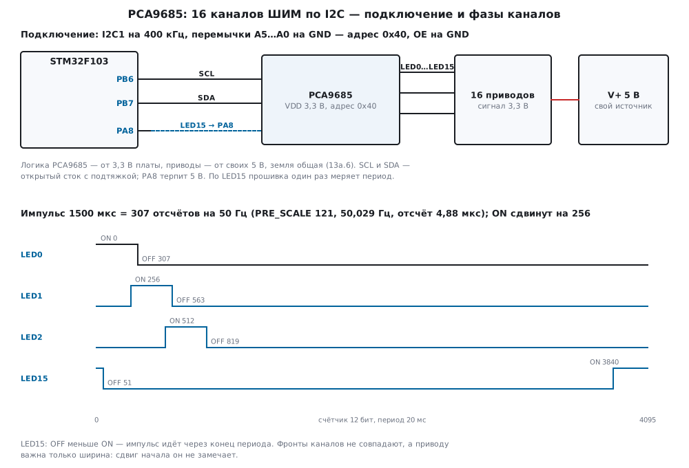
13в.2 Connecting to the F103 and initialisation
| PCA9685 pin | STM32F103 and other | Purpose |
|---|---|---|
| SCL | PB6 | I2C1 clock |
| SDA | PB7 | I2C1 data |
| VDD, GND | 3.3 V and ground | logic supply |
| V+ | a separate 5 V source | servo supply, does not go to the logic |
| A5…A0 | GND | address 0x40 |
| OE | GND | outputs enabled |
| LED15 | PA8 through a jumper | period measurement for calibration (13в.3) |
PB6 and PB7 are I2C1 pins, both FT, that is they withstand 5 V
(DocID13587, p. 32): a board with pull-ups to 5 V will not burn them. But
it is simpler to power the PCA9685 logic from 3.3 V — then the channel
outputs are 3.3 V too. Servos draw current in bursts, and their supply
V+ is not mixed with the logic: a separate source, a common ground, a
capacitor at the connector — as in 13а.6.
According to the manufacturer's documentation the address is 0x40 plus
the code on jumpers A5…A0. In the model jumpers 000000 gave 0x40 (byte on
the wire 0x80, 17.2), 000001 — 0x41, 111111 — 0x7F; at a wrong address
pca_init returned the refusal PCA_E_NACK. I2C1 is as in 15б.2:
400 kHz, CCR = F/S | 30, TRISE = 11; the F103 cannot go faster — up
to 400 kHz in fast mode (RM0008, p. 752).
Initialisation — the frequency, the output mode and the shared address switched off:
int pca_init(pca_t *d, uint8_t addr7, uint32_t freq_hz, uint8_t mode2)
{
    int rc;
    d->addr = addr7;
    d->xfers = d->errors = 0;
    if (d->osc_hz == 0u)
        d->osc_hz = PCA_OSC_HZ;
    if ((rc = pca_reg(d, PCA_MODE2, mode2)) != PCA_OK)     /* заодно: отвечает ли кто-то по адресу */
        return rc;
    return pca_set_freq(d, freq_hz);
}
The frequency is set by pca_set_freq, and the order in it is mandatory
(according to the manufacturer's documentation): PRE_SCALE is written
only in sleep, after waking the oscillator needs 500 µs, and if the
channels were running before sleep, writing 1 to RESTART restarts them:
/* PRE_SCALE пишется только во сне; после пробуждения — 500 мкс генератору и RESTART, если он взведён */
int pca_set_freq(pca_t *d, uint32_t freq_hz)
{
    uint8_t m, pre = pca_prescale(d->osc_hz, freq_hz);
    int rc;
    if ((rc = pca_get(d, PCA_MODE1, &m)) != PCA_OK)
        return rc;
    m &= (uint8_t)~(PCA_RESTART | PCA_SLEEP | PCA_ALLCALL);     /* общий адрес 0x70 — выключить */
    if ((rc = pca_reg(d, PCA_MODE1, m | PCA_AI | PCA_SLEEP)) != PCA_OK)
        return rc;
    if ((rc = pca_reg(d, PCA_PRE_SCALE, pre)) != PCA_OK)
        return rc;
    if ((rc = pca_reg(d, PCA_MODE1, m | PCA_AI)) != PCA_OK)    /* проснуться */
        return rc;
    pca_port_delay_us(PCA_WAKE_US);
    if ((rc = pca_get(d, PCA_MODE1, &m)) != PCA_OK)
        return rc;
    if (m & PCA_RESTART)                                /* каналы работали до сна: запустить их снова */
        rc = pca_reg(d, PCA_MODE1, m);
    if (rc == PCA_OK)
        d->prescale = pre;
    return rc;
}
In the model pca_init(&pca, 0x40, 50, PCA_OUTDRV) after power-up takes 6
exchanges: 80 01 04 (MODE2), a read of MODE1, 80 00 30 (sleep and
auto-increment), 80 FE 79 (PRE_SCALE = 121), 80 00 20 (wake up), a
read of MODE1. 485 µs on the bus, 985 µs with the pause. After that
MODE1 = 0x20, the frequency is 50.029 Hz. Reading a single byte on the
F103 follows a special order (RM0008, p. 764): clear ACK before clearing
ADDR, then STOP, then wait for RXNE — that is how pca_port_read in
the firmware is written.
13в.3 PWM frequency: the prescaler and the oscillator
A period is 4096 ticks, a tick is (PRE_SCALE + 1) oscillator cycles.
Hence the prescaler according to the manufacturer's documentation:
PRE_SCALE = round(osc / (4096 × f)) − 1, within 3 to 255.
/* PRE_SCALE = round(osc / (4096 × f)) − 1, в пределах 3…255 */
uint8_t pca_prescale(uint32_t osc_hz, uint32_t freq_hz)
{
    uint64_t div = (uint64_t)PCA_STEPS * (freq_hz ? freq_hz : 1u);
    uint64_t p = ((uint64_t)osc_hz + div / 2u) / div;   /* с округлением */
    if (p < PCA_PRE_MIN + 1u)
        p = PCA_PRE_MIN + 1u;
    if (p > PCA_PRE_MAX + 1u)
        p = PCA_PRE_MAX + 1u;
    return (uint8_t)(p - 1u);
}
The divider is an integer, so the frequency is not exactly the one asked for. In the model at 25 MHz:
| Asked | PRE_SCALE |
Got | Error | Without "− 1" |
|---|---|---|---|---|
| 24 Hz | 253 | 24.030 Hz | +0.123 % | 23.935 Hz |
| 50 Hz | 121 | 50.029 Hz | +0.058 % | 49.622 Hz |
| 200 Hz | 30 | 196.888 Hz | −1.556 % | 190.735 Hz |
| 1000 Hz | 5 | 1017.253 Hz | +1.725 % | 871.931 Hz |
| 1526 Hz | 3 | 1525.879 Hz | −0.008 % | 1220.703 Hz |
The limits are 23.842 Hz at 255 and 1525.879 Hz at 3: asking for 10 Hz
gave 255, for 2000 Hz — 3. At high frequencies the divider step is
coarse: 1000 Hz cannot be had more precisely than 1.7 %. For a servo this
does not matter — it needs the pulse width, not the frequency (13а.1), —
but the driver computes the width from the actual PRE_SCALE, not from
the frequency that was ordered.
The oscillator. The internal oscillator runs without a crystal, and how far its frequency is from 25 MHz in a particular chip, at which temperature and supply, was not checked here: there is no document. The model takes a deviation of 3 % either way (an assumption). The oscillator error goes into the pulse width one to one: the driver computes ticks for 25 MHz, and they are shorter or longer.
The cure is a measurement. Output LED15 with 50 % duty is wired to PA8, and the firmware once measures eight periods with the DWT cycle counter. After reset PA8 is an input without a pull-up (RM0008, p. 160) and withstands 5 V (DocID13587, p. 31):
/* период выхода LED15 в наносекундах: восемь периодов по счётчику тактов DWT */
static uint32_t period_ns(void)
{
    uint32_t a, b = 0;
    if (!edge(&a))
        return 0;
    for (int i = 0; i < 8; i++)
        if (!edge(&b))
            return 0;
    return (uint32_t)((uint64_t)(b - a) * 1000u / (72u * 8u));
}
From the period — the real oscillator frequency, and PRE_SCALE again:
/* по измеренному периоду выхода: osc = 4096 × (PRE_SCALE + 1) / T */
uint32_t pca_calibrate(pca_t *d, uint32_t period_ns)
{
    uint64_t n = (uint64_t)PCA_STEPS * (d->prescale + 1u) * 1000000000u;
    if (period_ns)
        d->osc_hz = (uint32_t)((n + period_ns / 2u) / period_ns);
    return d->osc_hz;
}
| Oscillator in the model | Before calibration: frequency | 1500 µs became | Angle | Period | After: PRE_SCALE |
Frequency | Pulse | Angle |
|---|---|---|---|---|---|---|---|---|
| 25.75 MHz (+3 %) | 51.530 Hz | 1454.5 µs | 81.8° | 19 406 291 ns | 125 | 49.894 Hz | 1502.2 µs | 90.4° |
| 24.25 MHz (−3 %) | 48.528 Hz | 1544.5 µs | 98.0° | 20 606 680 ns | 117 | 50.173 Hz | 1498.7 µs | 89.8° |
The angle is from the servo model of 13а.1: 1000 µs is 0°, 2000 µs is 180°. Before calibration the servo misses by 8°, after it — by less than half a degree; the measurement gave the oscillator frequency to the hertz: 25 750 000 and 24 250 000 Hz. What remains is the divider step and the tick step, not the oscillator.
13в.4 Servos: the pulse in ticks and phase spreading
At 50 Hz and PRE_SCALE = 121 a tick is 122 / 25 MHz = 4.88 µs. The
driver turns microseconds into ticks with rounding, using the oscillator
frequency it believes in:
/* микросекунды → отсчёты при текущих PRE_SCALE и частоте генератора, с округлением */
uint16_t pca_us_ticks(const pca_t *d, uint32_t us)
{
    uint64_t div = 1000000ull * (d->prescale + 1u);
    uint64_t t = ((uint64_t)us * d->osc_hz + div / 2u) / div;
    return (uint16_t)(t > PCA_STEPS - 1u ? PCA_STEPS - 1u : t);
}
| Pulse | 500 µs | 1000 µs | 1500 µs | 2000 µs | 2500 µs |
|---|---|---|---|---|---|
| Ticks | 102 | 205 | 307 | 410 | 512 |
| At the output in the model | 497.76 µs | 1000.4 µs | 1498.16 µs | 2000.8 µs | 2498.56 µs |
The travel 1000…2000 µs gets 205 ticks — 0.878° per tick, the wide travel 500…2500 µs gets 410 ticks, 0.439°. TIM2 in 13а.2 had a step of 1 µs, 0.18°: the PCA9685 is five times coarser, but the dead band of the servo model is 1° (13а.1), and a step of 0.878° is enough for it.
Phase spreading. If all channels have ON = 0, all 16 outputs turn
on at the same tick. The servo does not care where the pulse starts — the
width matters. So the driver shifts the start by 256 ticks per channel,
and the edges spread over the period:
/* заполнение 0…4096 → ON и OFF; spread — сдвиг начала на 256 отсчётов на канал */
void pca_duty(uint32_t ch, uint32_t duty, int spread, uint16_t *on, uint16_t *off)
{
    if (duty == 0u) {
        *on = 0;
        *off = PCA_FULL;                                /* всегда выключен */
    } else if (duty >= PCA_STEPS) {
        *on = PCA_FULL;                                 /* всегда включён */
        *off = 0;
    } else {
        *on = (uint16_t)(spread ? (ch % PCA_CHANNELS) * (PCA_STEPS / PCA_CHANNELS) : 0u);
        *off = (uint16_t)((*on + duty) % PCA_STEPS);    /* OFF < ON — импульс через конец периода */
    }
}
Channel 3 at 1500 µs is ON = 768, OFF = 1075; channel 15 at 2000 µs
is ON = 3840, OFF = 154, the pulse goes through the end of the
period, and in the model it is still 2000.8 µs. What the shift gives, the
model computes from the shape of all 16 outputs; the current is an
assumption: 20 mA per output while it is on, as for an LED. How much the
signal input of a servo draws was not checked.
| 16 channels | No shift: on at once | edges on one tick | current peak | With shift: on at once | edges | current peak | Mean current |
|---|---|---|---|---|---|---|---|
| servo, 1500 µs | 16 | 16 | 320 mA | 2 | 1 | 40 mA | 24 mA |
| duty 25 % | 16 | 16 | 320 mA | 4 | 2 | 80 mA | 80 mA |
| duty 50 % | 16 | 16 | 320 mA | 8 | 2 | 160 mA | 160 mA |
The mean current is the same, while the peak with the shift is 2–8 times
lower, and instead of 16 edges at once there are one or two. For servos
the main current is the motors on V+, and the shift does not remove
their bursts: a separate source and a staggered start help there (13а.6).
13в.5 LEDs: brightness, gamma, full on/off, outputs
Brightness is the duty from 0 to 4096. The eye does not see brightness linearly: half the duty looks much brighter than half. So the level is recalculated with a gamma — here 2.2, an assumption about perception, not data from a document. The driver has a table of 17 points and linear interpolation between them:
/* уровень 0…1024 → заполнение 0…4096 по гамме 2,2: таблица и линейная вставка между точками */
uint16_t pca_gamma(uint32_t level)
{
    if (level >= 1024u)
        return PCA_STEPS;
    uint32_t i = level >> 6, f = level & 63u;
    uint32_t a = gamma22[i], b = gamma22[i + 1u];
    return (uint16_t)(a + ((b - a) * f + 32u) / 64u);
}
| Level | 0 | 16 | 32 | 64 | 128 | 256 | 512 | 768 | 1000 | 1024 |
|---|---|---|---|---|---|---|---|---|---|---|
| Duty | 0 | 2 | 5 | 9 | 42 | 194 | 891 | 2175 | 3893 | 4096 |
The interpolation departs from the exact curve 4096 × (level / 1024)^2.2 by no more than 5.8 ticks. The first level that glows is level 4; of 1025 levels, 936 give different duties. This is where the 12 bits are needed: if the same duty is rounded to 8 bits, the first 53 levels are complete darkness, and light appears only from level 54.
Full on and off. An ordinary pulse cannot give 100 %: ON = 0,
OFF = 4095 — the output is on for 0.999756 of the period, one tick
short. So pca_duty sets bit 12 in ON ("always on") for 4096 and bit
12 in OFF for 0. If both are set, according to the manufacturer's
documentation "off" wins — in the model the output is 0.
Push-pull output or open drain. OUTDRV in MODE2: 1 — the output
itself drives both 0 and 1, 0 — open drain: it only pulls to ground and
releases the pin instead of a one. INVRT inverts the output. An LED is
connected either from the pin to ground (lit at 1) or from the plus to
the pin (lit at 0). In the model at 25 % duty:
MODE2 |
Output | LED to ground | LED from plus |
|---|---|---|---|
| 0x04 | push-pull | 0.25 | 0.75 |
| 0x14 | push-pull, INVRT |
0.75 | 0.25 |
| 0x00 | open drain | 0 | 0.75 |
| 0x10 | open drain, INVRT |
0 | 0.25 |
An open drain will not light an LED to ground at all. An LED from the
plus is "the other way round": without INVRT 25 % gives 75 % of light.
It is driven with INVRT — or the duty is computed as 4096 − brightness.
The output current and the resistor follow the manufacturer's
documentation for the chip and the LED; they were not computed here.
13в.6 All 16 channels in one transaction
With auto-increment the register number grows after every byte, and 16 channels are one write: the number 0x06 and 64 bytes.
/* все 16 каналов одной транзакцией: 1 + 64 байта, выходы меняются вместе по STOP */
int pca_write_all(pca_t *d, const uint16_t on[16], const uint16_t off[16])
{
    uint8_t b[1 + 4 * PCA_CHANNELS];
    b[0] = PCA_LED0_ON_L;
    for (uint32_t i = 0; i < PCA_CHANNELS; i++) {
        b[1 + 4 * i] = (uint8_t)on[i];
        b[2 + 4 * i] = (uint8_t)(on[i] >> 8);
        b[3 + 4 * i] = (uint8_t)off[i];
        b[4 + 4 * i] = (uint8_t)(off[i] >> 8);
    }
    return xfer_done(d, pca_port_write(d->addr, b, sizeof b));
}
According to the manufacturer's documentation the outputs take the new
values on STOP (or on the ACK of every byte if OCH = 1). So one
transaction means all 16 channels change at once. Bus time in the model:
| Write | SCL clocks | 100 kHz | 400 kHz | Share of a 20 ms frame, 100 / 400 kHz |
|---|---|---|---|---|
| 16 channels in one transaction | 596 | 5960 µs | 1490 µs | 29.8 % / 7.45 % |
| 16 channels one by one | 16 × 56 | 8960 µs | 2240 µs | 44.8 % / 11.2 % |
| one channel | 56 | 560 µs | 140 µs | |
ALL_LED — all at once with one value |
56 | 560 µs | 140 µs | |
| reading one register | 39 | 390 µs | 97.5 µs |
Synchronism. Channels written one by one get the new values at
different moments, and some of them already in the next period. In the
model a new value takes effect from the period after STOP (an
assumption); 400 frames with a random counter phase:
| How it was written | 100 kHz | 400 kHz |
|---|---|---|
| one transaction | 0 of 400 | 0 of 400 |
| 16 transactions | 159 of 400 (39.8 %) | 48 of 400 (12 %) |
In two frames out of five at 100 kHz some servos moved one period later than the rest. One transaction does not allow this.
Smooth motion — as in 13а.4, only the step is made not by a timer interrupt but by a frame every 20 ms: the firmware computes 16 pulses and writes them in one transaction. The travel 1000 → 2000 µs at 20 µs per frame takes 50 frames, 1 s; the ticks go from 209 to 410 in steps of 4–5 (20 µs is 4.1 ticks). At 400 kHz a frame occupies the bus for 1490 µs — 7.45 % of the time, and the same bus still has room for sensors.
13в.7 Pitfalls
PRE_SCALE "did not get written". It was written without putting the
chip to sleep — according to the manufacturer's documentation the write
is lost. In the model PRE_SCALE stayed 30 (0x1E, after power-up), the
period is 5079 µs instead of 20 ms, and the driver, sure of 121, gave
307 ticks — a pulse of 380.7 µs instead of 1500. The servo hits its
stop. Only pca_set_freq: sleep, PRE_SCALE, wake-up.
A channel was written — the output is silent. No AI: after power-up
auto-increment is off, and all four bytes land in one register
LED0_ON_L. In the model after writing 1500 µs the channel registers
are 01 00 00 10: the "always off" bit is in place, pulses in 100 ms —
0. pca_set_freq sets AI in MODE1.
A foreign device at 0x70 rewrites the PCA9685. After power-up
ALLCALL = 1, and the chip answers 0x70. In the model a write of two
bytes 00 01 to a device with address 0x70 changed the PCA9685's
MODE1 from 0x11 to 0x01 — it woke up. After pca_init (ALLCALL
cleared) the same write left MODE1 = 0x20 alone. Two answers to one
address are also a fight on the line during reads.
After sleep the channels stand still. Going to sleep with the
channels running sets RESTART. In the model the servo got 5 pulses in
100 ms; after sleep MODE1 = 0xB0, after waking — 0xA0 and 0 pulses.
Writing 1 to RESTART from pca_set_freq gave back 0x20 and 5 pulses.
Writing 0 to RESTART changes nothing — only a one clears it, and only
500 µs after waking.
Forgot the "− 1". PRE_SCALE = 122 instead of 121 — 49.622 Hz, and
a pulse computed for 121 came out 1510.4 µs instead of 1500. A trifle for
a servo, but at 1000 Hz the same "− 1" gives 871.931 Hz instead of
1017.253 (13в.3).
The controller resets when the servos move. V+ is taken from the
same 5 V or 3.3 V as the logic. A separate source for V+, a common
ground, a capacitor at the connector (13а.6).
5 V and pull-ups. A PCA9685 board on 5 V with pull-ups to 5 V: PB6 and PB7 are FT (p. 32), PA8 too (p. 31), but PA0…PA3 are not (13а.6), a channel output must not go to them. The simplest is the logic on 3.3 V.
The LED glows the other way round. It is connected from the plus to
the pin, and there is no INVRT: 25 % gives 75 % of light (13в.5).
13в.8 Summary
- PCA9685: 16 channels of 12 bits, a 25 MHz oscillator, one frequency for
all —
PRE_SCALE= round(osc / (4096 × f)) − 1, from 3 to 255: from 23.842 to 1525.879 Hz; 50 Hz is 121, 50.029 Hz. - F103: I2C1 on PB6 and PB7 (FT), 400 kHz; address 0x40 plus jumpers A5…A0; initialisation — 6 exchanges, 985 µs.
PRE_SCALEonly in sleep; after waking 500 µs andRESTART;AIfor multi-byte writes; clearALLCALL.- A servo at 50 Hz: a tick is 4.88 µs, 1500 µs is 307 ticks, 0.878° per
tick; shifting
ONby 256 gives a current peak of 40 mA instead of 320 mA in the model. - An oscillator 3 % off — the servo misses by 8°; measuring the period on
LED15 and
pca_calibrate— less than half a degree. - LEDs: gamma 2.2 from a 17-point table, 936 distinct duties; 4096 and 0 via bit 12; an open drain will not light an LED to ground.
- 16 channels in one transaction — 1490 µs at 400 kHz and 5960 µs at
100 kHz, all change on one
STOP; one by one — 2240 µs and desynchronisation in 12 % of frames.
Full sources
pca13d.h — registers, MODE1 and MODE2 bits, the port and the driver functions.
/* pca13d.h — раздел 13в: драйвер PCA9685 (16 каналов ШИМ по I2C) без регистров микроконтроллера.
 * Драйвер говорит с микросхемой только через три функции порта (pca_port_*): в прошивке fw13d.c их
 * делает I2C1 STM32F103, в стенде host13d.c — модель model13d.py.
 * Карта регистров и биты — по документации производителя; документа в проекте нет, адреса регистров
 * и биты совпадают с открытыми драйверами Zephyr, rusEFI и Klipper; с микросхемой не сверено. */
#ifndef PCA13D_H
#define PCA13D_H
#include <stdint.h>

/* ── регистры ─────────────────────────────────────────────────────────── */
#define PCA_MODE1         0x00u
#define PCA_MODE2         0x01u
#define PCA_LED0_ON_L     0x06u         /* канал n: 0x06 + 4n — ON_L, ON_H, OFF_L, OFF_H */
#define PCA_ALL_LED_ON_L  0xFAu         /* запись сразу во все 16 каналов */
#define PCA_PRE_SCALE     0xFEu         /* пишется только при SLEEP = 1 */

/* ── MODE1 ────────────────────────────────────────────────────────────── */
#define PCA_RESTART       0x80u         /* 1 — каналы остановлены сном; запись 1 перезапускает */
#define PCA_AI            0x20u         /* автоинкремент номера регистра */
#define PCA_SLEEP         0x10u         /* генератор выключен */
#define PCA_ALLCALL       0x01u         /* отвечать и на общий адрес 0x70 */
/* ── MODE2 ────────────────────────────────────────────────────────────── */
#define PCA_INVRT         0x10u         /* инверсия выходов */
#define PCA_OCH           0x08u         /* 0 — выходы меняются по STOP, 1 — по ACK */
#define PCA_OUTDRV        0x04u         /* 1 — двухтактный выход, 0 — открытый сток */

#define PCA_FULL          0x1000u       /* бит 12 в ON или OFF: канал всегда включён или всегда выключен */
#define PCA_STEPS         4096u         /* 12 бит: отсчётов на период */
#define PCA_CHANNELS      16u
#define PCA_OSC_HZ        25000000u     /* внутренний генератор */
#define PCA_ADDR_BASE     0x40u         /* A5…A0 на GND */
#define PCA_ADDR_ALLCALL  0x70u
#define PCA_PRE_MIN       3u
#define PCA_PRE_MAX       255u
#define PCA_WAKE_US       500u          /* генератору после SLEEP = 0 */

enum { PCA_OK = 0, PCA_E_NACK = -1, PCA_E_BUS = -2 };

typedef struct {
    uint8_t addr;                       /* семибитный адрес: 0x40 + перемычки */
    uint8_t prescale;                   /* что драйвер записал в PRE_SCALE */
    uint32_t osc_hz;                    /* частота генератора, которой верит драйвер: 25 МГц или после калибровки */
    uint32_t xfers, errors;             /* обменов по I2C и ошибок */
} pca_t;

/* ── порт: в прошивке — I2C1, в стенде — строки к модели ──────────────── */
/* записать n байт одной транзакцией: START, адрес, байты, STOP; 0, PCA_E_NACK или PCA_E_BUS */
int pca_port_write(uint8_t addr7, const uint8_t *tx, uint32_t n);
/* прочитать один байт регистра reg: запись номера, повторный старт, чтение */
int pca_port_read(uint8_t addr7, uint8_t reg, uint8_t *v);
void pca_port_delay_us(uint32_t us);

/* ── драйвер ──────────────────────────────────────────────────────────── */
uint8_t pca_prescale(uint32_t osc_hz, uint32_t freq_hz);
uint32_t pca_freq_mhz(uint32_t osc_hz, uint8_t prescale);
int pca_reg(pca_t *d, uint8_t reg, uint8_t v);
int pca_get(pca_t *d, uint8_t reg, uint8_t *v);
int pca_init(pca_t *d, uint8_t addr7, uint32_t freq_hz, uint8_t mode2);
int pca_set_freq(pca_t *d, uint32_t freq_hz);
uint32_t pca_calibrate(pca_t *d, uint32_t period_ns);
uint16_t pca_us_ticks(const pca_t *d, uint32_t us);
void pca_duty(uint32_t ch, uint32_t duty, int spread, uint16_t *on, uint16_t *off);
void pca_servo(const pca_t *d, uint32_t ch, uint32_t us, int spread, uint16_t *on, uint16_t *off);
uint16_t pca_gamma(uint32_t level);
int pca_channel(pca_t *d, uint32_t ch, uint16_t on, uint16_t off);
int pca_write_all(pca_t *d, const uint16_t on[16], const uint16_t off[16]);
int pca_all_off(pca_t *d);

#endif
pca13d.c — the driver: frequency, calibration, ticks, phases, gamma, writing all channels.
/* pca13d.c — раздел 13в: драйвер PCA9685 по I2C. Один и тот же файл собирается в прошивку (armclang,
 * Cortex-M3) и в стенд на компьютере (gcc): микроконтроллера он не знает, только порт pca_port_*. */
#include "pca13d.h"

/* 4096 × (i/16)^2,2 — гамма 2,2 по 17 точкам */
static const uint16_t gamma22[17] = {0, 9, 42, 103, 194, 317, 473, 665, 891, 1155, 1456, 1796, 2175, 2594, 3053, 3554, 4096};

/* PRE_SCALE = round(osc / (4096 × f)) − 1, в пределах 3…255 */
uint8_t pca_prescale(uint32_t osc_hz, uint32_t freq_hz)
{
    uint64_t div = (uint64_t)PCA_STEPS * (freq_hz ? freq_hz : 1u);
    uint64_t p = ((uint64_t)osc_hz + div / 2u) / div;   /* с округлением */
    if (p < PCA_PRE_MIN + 1u)
        p = PCA_PRE_MIN + 1u;
    if (p > PCA_PRE_MAX + 1u)
        p = PCA_PRE_MAX + 1u;
    return (uint8_t)(p - 1u);
}

/* фактическая частота в миллигерцах: osc / (4096 × (PRE_SCALE + 1)) */
uint32_t pca_freq_mhz(uint32_t osc_hz, uint8_t prescale)
{
    uint64_t div = (uint64_t)PCA_STEPS * (prescale + 1u);
    return (uint32_t)(((uint64_t)osc_hz * 1000u + div / 2u) / div);
}

static int xfer_done(pca_t *d, int rc)
{
    d->xfers++;
    if (rc)
        d->errors++;
    return rc;
}

int pca_reg(pca_t *d, uint8_t reg, uint8_t v)
{
    uint8_t b[2] = {reg, v};
    return xfer_done(d, pca_port_write(d->addr, b, 2));
}

int pca_get(pca_t *d, uint8_t reg, uint8_t *v)
{
    return xfer_done(d, pca_port_read(d->addr, reg, v));
}

/* PRE_SCALE пишется только во сне; после пробуждения — 500 мкс генератору и RESTART, если он взведён */
int pca_set_freq(pca_t *d, uint32_t freq_hz)
{
    uint8_t m, pre = pca_prescale(d->osc_hz, freq_hz);
    int rc;
    if ((rc = pca_get(d, PCA_MODE1, &m)) != PCA_OK)
        return rc;
    m &= (uint8_t)~(PCA_RESTART | PCA_SLEEP | PCA_ALLCALL);     /* общий адрес 0x70 — выключить */
    if ((rc = pca_reg(d, PCA_MODE1, m | PCA_AI | PCA_SLEEP)) != PCA_OK)
        return rc;
    if ((rc = pca_reg(d, PCA_PRE_SCALE, pre)) != PCA_OK)
        return rc;
    if ((rc = pca_reg(d, PCA_MODE1, m | PCA_AI)) != PCA_OK)    /* проснуться */
        return rc;
    pca_port_delay_us(PCA_WAKE_US);
    if ((rc = pca_get(d, PCA_MODE1, &m)) != PCA_OK)
        return rc;
    if (m & PCA_RESTART)                                /* каналы работали до сна: запустить их снова */
        rc = pca_reg(d, PCA_MODE1, m);
    if (rc == PCA_OK)
        d->prescale = pre;
    return rc;
}

int pca_init(pca_t *d, uint8_t addr7, uint32_t freq_hz, uint8_t mode2)
{
    int rc;
    d->addr = addr7;
    d->xfers = d->errors = 0;
    if (d->osc_hz == 0u)
        d->osc_hz = PCA_OSC_HZ;
    if ((rc = pca_reg(d, PCA_MODE2, mode2)) != PCA_OK)     /* заодно: отвечает ли кто-то по адресу */
        return rc;
    return pca_set_freq(d, freq_hz);
}

/* по измеренному периоду выхода: osc = 4096 × (PRE_SCALE + 1) / T */
uint32_t pca_calibrate(pca_t *d, uint32_t period_ns)
{
    uint64_t n = (uint64_t)PCA_STEPS * (d->prescale + 1u) * 1000000000u;
    if (period_ns)
        d->osc_hz = (uint32_t)((n + period_ns / 2u) / period_ns);
    return d->osc_hz;
}

/* микросекунды → отсчёты при текущих PRE_SCALE и частоте генератора, с округлением */
uint16_t pca_us_ticks(const pca_t *d, uint32_t us)
{
    uint64_t div = 1000000ull * (d->prescale + 1u);
    uint64_t t = ((uint64_t)us * d->osc_hz + div / 2u) / div;
    return (uint16_t)(t > PCA_STEPS - 1u ? PCA_STEPS - 1u : t);
}

/* заполнение 0…4096 → ON и OFF; spread — сдвиг начала на 256 отсчётов на канал */
void pca_duty(uint32_t ch, uint32_t duty, int spread, uint16_t *on, uint16_t *off)
{
    if (duty == 0u) {
        *on = 0;
        *off = PCA_FULL;                                /* всегда выключен */
    } else if (duty >= PCA_STEPS) {
        *on = PCA_FULL;                                 /* всегда включён */
        *off = 0;
    } else {
        *on = (uint16_t)(spread ? (ch % PCA_CHANNELS) * (PCA_STEPS / PCA_CHANNELS) : 0u);
        *off = (uint16_t)((*on + duty) % PCA_STEPS);    /* OFF < ON — импульс через конец периода */
    }
}

void pca_servo(const pca_t *d, uint32_t ch, uint32_t us, int spread, uint16_t *on, uint16_t *off)
{
    pca_duty(ch, pca_us_ticks(d, us), spread, on, off);
}

/* уровень 0…1024 → заполнение 0…4096 по гамме 2,2: таблица и линейная вставка между точками */
uint16_t pca_gamma(uint32_t level)
{
    if (level >= 1024u)
        return PCA_STEPS;
    uint32_t i = level >> 6, f = level & 63u;
    uint32_t a = gamma22[i], b = gamma22[i + 1u];
    return (uint16_t)(a + ((b - a) * f + 32u) / 64u);
}

/* один канал: номер регистра и четыре байта, младший первым; нужен автоинкремент (AI) */
int pca_channel(pca_t *d, uint32_t ch, uint16_t on, uint16_t off)
{
    uint8_t b[5] = {(uint8_t)(PCA_LED0_ON_L + 4u * (ch % PCA_CHANNELS)), (uint8_t)on, (uint8_t)(on >> 8),
                    (uint8_t)off, (uint8_t)(off >> 8)};
    return xfer_done(d, pca_port_write(d->addr, b, 5));
}

/* все 16 каналов одной транзакцией: 1 + 64 байта, выходы меняются вместе по STOP */
int pca_write_all(pca_t *d, const uint16_t on[16], const uint16_t off[16])
{
    uint8_t b[1 + 4 * PCA_CHANNELS];
    b[0] = PCA_LED0_ON_L;
    for (uint32_t i = 0; i < PCA_CHANNELS; i++) {
        b[1 + 4 * i] = (uint8_t)on[i];
        b[2 + 4 * i] = (uint8_t)(on[i] >> 8);
        b[3 + 4 * i] = (uint8_t)off[i];
        b[4 + 4 * i] = (uint8_t)(off[i] >> 8);
    }
    return xfer_done(d, pca_port_write(d->addr, b, sizeof b));
}

int pca_all_off(pca_t *d)
{
    uint8_t b[5] = {PCA_ALL_LED_ON_L, 0, 0, 0, PCA_FULL >> 8};
    return xfer_done(d, pca_port_write(d->addr, b, 5));
}
fw13d.c — STM32F103 firmware: I2C1 at 400 kHz, period measurement on PA8, 16 servos in 20 ms frames.
/* fw13d.c — раздел 13в: PCA9685 на STM32F103 (BluePill), 72 МГц, APB1 = 36 МГц.
 * I2C1: PB6 — SCL, PB7 — SDA (открытый сток, 400 кГц). Перемычки A5…A0 на GND — адрес 0x40, OE на GND.
 * Выход LED15 перемычкой на PA8 (вход, допуск 5 В): по нему один раз меряется период и калибруется частота
 * генератора. Потом 16 приводов раз в 20 мс ходят 1000 ↔ 2000 мкс по 20 мкс за кадр, кадр — одна транзакция.
 * Тактирование до 72 МГц — как в разделе 6. */
#include "stm32f10x.h"
#include "pca13d.h"

#define CPU_HZ          72000000u
#define APB1_MHZ        36u
#define I2C_TIMEOUT_US  1000u           /* 65 байт на 400 кГц — 1490 мкс, но ждём каждый флаг отдельно */
#define FRAME_US        20000u

static pca_t pca;
volatile uint32_t bus_errors, period_ns_meas;

static int expired(uint32_t t0, uint32_t us)
{
    return DWT->CYCCNT - t0 >= us * (CPU_HZ / 1000000u);
}

void pca_port_delay_us(uint32_t us)
{
    uint32_t t0 = DWT->CYCCNT;
    while (!expired(t0, us)) {
    }
}

static void i2c1_init(void)
{
    RCC->APB2ENR |= RCC_APB2ENR_IOPAEN | RCC_APB2ENR_IOPBEN | RCC_APB2ENR_AFIOEN;
    RCC->APB1ENR |= RCC_APB1ENR_I2C1EN;
    /* PB6, PB7 — альтернативная функция, открытый сток, 50 МГц (1111); PA8 — вход без подтяжки (0100, как после сброса) */
    GPIOB->CRL = (GPIOB->CRL & 0x00FFFFFFu) | 0xFF000000u;
    GPIOA->CRH = (GPIOA->CRH & ~0xFu) | 0x4u;
    I2C1->CR1 = 0;                                      /* настраивать при PE = 0 */
    I2C1->CR2 = APB1_MHZ;
    I2C1->CCR = I2C_CCR_FS | 30u;                       /* DUTY = 0: 36 МГц / (3 × 30) = 400 кГц */
    I2C1->TRISE = APB1_MHZ * 300u / 1000u + 1u;         /* 300 нс × 36 МГц = 10,8 → 10 + 1 = 11 */
    I2C1->CR1 = I2C_CR1_PE;
}

static int sr1_wait(uint16_t mask)
{
    uint32_t t0 = DWT->CYCCNT;
    while (!(I2C1->SR1 & mask)) {
        if (I2C1->SR1 & I2C_SR1_AF)
            return PCA_E_NACK;                          /* адрес или байт не подтверждён */
        if (expired(t0, I2C_TIMEOUT_US))
            return PCA_E_BUS;
    }
    return PCA_OK;
}

static int fail(int rc)
{
    I2C1->CR1 |= I2C_CR1_STOP;
    I2C1->SR1 = (uint16_t)~I2C_SR1_AF;                  /* AF снимается записью нуля */
    return rc;
}

/* START и байт адреса; ADDR не снят — его снимает вызывающий чтением SR2 */
static int start(uint8_t addr_byte)
{
    int rc;
    uint32_t t0 = DWT->CYCCNT;
    while (I2C1->SR2 & I2C_SR2_BUSY) {                  /* SDA держит ведомый — раздел 17.6 */
        if (expired(t0, I2C_TIMEOUT_US))
            return PCA_E_BUS;
    }
    I2C1->CR1 |= I2C_CR1_START;
    if ((rc = sr1_wait(I2C_SR1_SB)) != PCA_OK)
        return rc;
    I2C1->DR = addr_byte;
    return sr1_wait(I2C_SR1_ADDR);
}

int pca_port_write(uint8_t addr7, const uint8_t *tx, uint32_t n)
{
    int rc;
    if ((rc = start((uint8_t)(addr7 << 1))) != PCA_OK)
        return fail(rc);
    (void)I2C1->SR2;
    for (uint32_t i = 0; i < n; i++) {
        if ((rc = sr1_wait(I2C_SR1_TXE)) != PCA_OK)
            return fail(rc);
        I2C1->DR = tx[i];
    }
    if ((rc = sr1_wait(I2C_SR1_BTF)) != PCA_OK)
        return fail(rc);
    I2C1->CR1 |= I2C_CR1_STOP;                          /* по STOP выходы PCA9685 берут новые значения */
    return PCA_OK;
}

int pca_port_read(uint8_t addr7, uint8_t reg, uint8_t *v)
{
    int rc;
    if ((rc = start((uint8_t)(addr7 << 1))) != PCA_OK)
        return fail(rc);
    (void)I2C1->SR2;
    if ((rc = sr1_wait(I2C_SR1_TXE)) != PCA_OK)
        return fail(rc);
    I2C1->DR = reg;
    if ((rc = sr1_wait(I2C_SR1_BTF)) != PCA_OK)
        return fail(rc);
    I2C1->CR1 |= I2C_CR1_START;                         /* повторный старт: SR2.BUSY ещё 1, start() не годится */
    if ((rc = sr1_wait(I2C_SR1_SB)) != PCA_OK)
        return fail(rc);
    I2C1->DR = (uint8_t)(addr7 << 1 | 1u);
    if ((rc = sr1_wait(I2C_SR1_ADDR)) != PCA_OK)
        return fail(rc);
    I2C1->CR1 &= (uint16_t)~I2C_CR1_ACK;                /* один байт: RM0008, с. 764 — ACK снять до ADDR */
    (void)I2C1->SR2;
    I2C1->CR1 |= I2C_CR1_STOP;
    if ((rc = sr1_wait(I2C_SR1_RXNE)) != PCA_OK)
        return fail(rc);
    *v = (uint8_t)I2C1->DR;
    return PCA_OK;
}

/* фронт на PA8: дождаться нуля, потом единицы; 0 — нет сигнала за 50 мс */
static int edge(uint32_t *t)
{
    uint32_t t0 = DWT->CYCCNT;
    while (GPIOA->IDR & (1u << 8)) {
        if (expired(t0, 50000u))
            return 0;
    }
    while (!(GPIOA->IDR & (1u << 8))) {
        if (expired(t0, 50000u))
            return 0;
    }
    *t = DWT->CYCCNT;
    return 1;
}

/* период выхода LED15 в наносекундах: восемь периодов по счётчику тактов DWT */
static uint32_t period_ns(void)
{
    uint32_t a, b = 0;
    if (!edge(&a))
        return 0;
    for (int i = 0; i < 8; i++)
        if (!edge(&b))
            return 0;
    return (uint32_t)((uint64_t)(b - a) * 1000u / (72u * 8u));
}

int main(void)
{
    static uint16_t on[16], off[16];
    uint32_t us = 1000u, t0;
    int32_t dir = 20;
    CoreDebug->DEMCR |= CoreDebug_DEMCR_TRCENA_Msk;
    DWT->CYCCNT = 0;
    DWT->CTRL |= DWT_CTRL_CYCCNTENA_Msk;
    i2c1_init();
    while (pca_init(&pca, PCA_ADDR_BASE, 50u, PCA_OUTDRV) != PCA_OK)
        pca_port_delay_us(100000u);                     /* нет ответа: провод, адрес, питание */
    /* калибровка: LED15 — половина периода, его фронты считает PA8 */
    pca_duty(15u, PCA_STEPS / 2u, 0, &on[15], &off[15]);
    if (pca_channel(&pca, 15u, on[15], off[15]) == PCA_OK) {
        period_ns_meas = period_ns();
        if (period_ns_meas) {
            (void)pca_calibrate(&pca, period_ns_meas);
            (void)pca_set_freq(&pca, 50u);              /* PRE_SCALE заново — уже по настоящей частоте */
        }
    }
    t0 = DWT->CYCCNT;
    for (;;) {
        for (uint32_t ch = 0; ch < 16u; ch++)
            pca_servo(&pca, ch, us, 1, &on[ch], &off[ch]);
        if (pca_write_all(&pca, on, off) != PCA_OK)
            bus_errors++;
        us = (uint32_t)((int32_t)us + dir);
        if (us >= 2000u || us <= 1000u)
            dir = -dir;
        while (!expired(t0, FRAME_US)) {
        }
        t0 += FRAME_US * (CPU_HZ / 1000000u);
    }
}
Next: section 14 "ADC" — digitising signals, conversion modes and working together with DMA and a timer.