 Embedded HandbookApps
57. PWM in power electronics
A microcontroller can only switch on and off. To get "half", it switches on half of the time. Everything grows out of this simple idea: brightness control, motor speed, soldering iron temperature, voltage converters.
This section covers what you need to understand when PWM drives not an LED but power: how the average value differs from the RMS value, how frequency trades against resolution, why a brightness scale looks uneven and what happens to the current in a motor winding.
The mechanics of the timers themselves are in section 13, high resolution is in section 46, switches are in section 52.
Terms used in the documentation
Term Meaning duty cycle the fraction of the period the output is on average / RMS value mean value / root-mean-square value resolution the number of distinguishable levels gamma correction compensating the eye's non-linear response flicker visible blinking of a light source current ripple the AC part of the current around its average electrical time constant L/R of a winding dead time a pause between turning one switch off and the other on half-bridge, full bridge two switches / four switches feeding a load complementary outputs a pair of outputs in opposite states centre-aligned PWM PWM with the pulse centred in the period
57.1 Frequency and resolution share one clock
PWM resolution is the number of timer clock cycles that fit into one period. Hence a direct trade-off: the higher the frequency, the coarser the step.
| PWM frequency | Steps with a 72 MHz timer | Bits |
|---|---|---|
| 1 kHz | 36000 (prescaler 2) | 15.1 |
| 20 kHz | 3600 | 11.8 |
| 100 kHz | 720 | 9.5 |
| 500 kHz | 144 | 7.2 |
The counter width also sets a ceiling: the F103 timers are 16-bit, and a period holds no more than 65536 steps. 72000 does not fit — at 1 kHz you need a prescaler of 2.
At 20 kHz (the usual frequency for motors — above the audible range) you get 3600 steps: eleven bits fit, twelve no longer do. At 500 kHz not even eight fit — that is why power converters get a separate high-resolution timer (section 46.1).
How the frequency is chosen:
- above the audible range (from 18–20 kHz) if the load is a winding: otherwise it will sing;
- high enough for the load to smooth it out (see below);
- no higher than needed, because switching losses grow in direct proportion to frequency (section 52.3).
57.2 Average and RMS are different quantities
This is the first place where people go wrong.
| Duty cycle | Average | RMS |
|---|---|---|
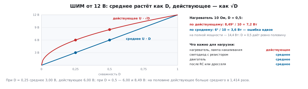
| 0.25 | 3.00 V | 6.00 V |
| 0.50 | 6.00 V | 8.49 V |
| 1.00 | 12.00 V | 12.00 V |
The RMS value equals U · √D — at half duty it is
1.414 times the average.
Heating depends on the RMS value. A 10 Ω heater at a duty cycle of 0.5 from 12 V gets 7.2 W, not the 3.6 you would get by calculating from the average. The error is exactly a factor of two.
A useful check: at full power the heater takes 14.4 W, so a duty cycle of 0.5 gives exactly 50 % of the power. For a purely resistive load the power is directly proportional to the duty cycle — but you only get this through the RMS value, not through the average.
What applies where:
| Load | What matters |
|---|---|
| heater, incandescent lamp | RMS (power) |
| LED with a resistor | average (the current is set by the resistor) |
| motor | average (torque follows the average current) |
| after an RC filter or an inductor | average (the AC component is smoothed) |
57.3 LED: brightness and the eye
In an LED the current is set by the resistor, so brightness is proportional to the average current: duty 0.25 — 2.5 mA, 0.5 — 5 mA, 1.0 — 10 mA.
But the eye perceives brightness non-linearly, roughly as the power 1/2.2:
| Duty cycle | Looks like |
|---|---|
| 0.10 | 35 % |
| 0.25 | 53 % |
| 0.50 | 73 % |
Half the duty cycle looks like three quarters of the brightness. That is why a linear control scale looks uneven: at the bottom brightness changes sharply, at the top it barely changes.
The cure is gamma correction: to get "half brightness to the eye", you need a duty cycle of 0.218 — code 891 of 4095, not 2048. In practice you use a precomputed table of 32–256 values: it is faster, and it lets you fit the scale to a particular LED.
57.4 Flicker
The eye does not notice flicker above about 60 Hz when looking steadily. But that does not mean 100 Hz is enough:
- when the eye or head moves, a 100 Hz source breaks up into a "comb" of separate flashes;
- peripheral vision is more sensitive than central vision;
- a camera records stripes at any frequency that is not a multiple of its exposure.
The practical limit is from 1 kHz, and it is cheap: the resolution at 1 kHz is excessive anyway (36000 steps).
A separate case is multiplexed display: four digits switched in turn at an overall rate of 1 kHz give each one 250 Hz and only 25 % of the time lit. Brightness drops fourfold; it is compensated by raising the pulse current, but not above what the LED allows in pulsed mode.
57.5 Motor: the current does not follow the voltage
A winding is an inductance, and the current in it does not change instantly. For a motor with an inductance of 1 mH and a resistance of 2 Ω the electrical time constant is 500 µs, which is ten PWM periods at 20 kHz. The current simply has no time to change noticeably within a period; it flows almost steadily, with small ripple.
At a duty cycle of 0.5 and 20 kHz the ripple is 150 mA peak-to-peak with an average current of 3 A — 5 %, quite acceptable.
Lower the frequency to 1 kHz — the period becomes twice as long as the time
constant, and the current no longer flows steadily: it swings between 1.6 and 4.4 A, a swing of
2.8 A — almost equal to the average. The formula U·D·(1−D)/(L·f) would give
3 A: it holds only while the period is much shorter than the time constant. The current
does not drop to zero, but the motor torque follows the current — the motor
will hum at the PWM frequency, and the winding heating, which is calculated from the
RMS current, will grow by about 8 % for the same useful work.
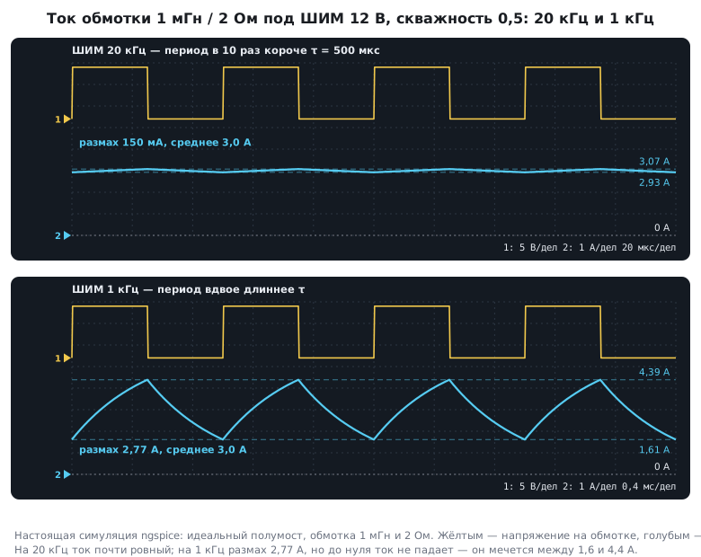
Hence the rule for an inductive load: the PWM period must be much shorter than the electrical time constant. Ten times shorter is good.
A mandatory companion is a path for the current during the off time: a freewheeling diode with a single switch (section 51.2) or the second switch of a half-bridge.
57.6 Half-bridge and dead time
When the load must be driven in both directions (a motor forward and back, a converter), one switch is not enough: you need a half-bridge of a high-side and a low-side switch, and more often a full bridge of four.
The high-side and low-side switches must never be on at the same time — that is a short circuit of the supply through both switches. Between turning one off and turning the other on, a dead time is inserted (section 46.3).
It is not free. The interval is inserted twice per period:
| Frequency | Two intervals of 500 ns |
|---|---|
| 1 kHz | 0.1 % of the period |
| 20 kHz | 2.0 % |
| 100 kHz | 10 % |
At 100 kHz a tenth of the period is wasted, and near zero duty cycle a dead zone appears. Besides, the interval distorts the output voltage: at 20 kHz that is 120 mV out of 12 V, about 1 %. A controller (section 47) compensates for this error, but you need to know about it — especially when driving a motor at low speed, where it causes jerks.
Hence: the dead time is chosen as the minimum sufficient for the particular switches and driver, not "with a bigger margin".
57.7 Centre alignment
Ordinary PWM starts the pulse at the beginning of the period (edge alignment). Centre-aligned PWM builds the pulse symmetrically around the middle: the counter counts up and down.
Why you need it:
- in a three-phase circuit symmetric pulses give less noise and smaller current ripple;
- the current measurement falls in the middle of the pulse, where the transients are already over — this is the very ADC triggering from a timer (section 14.5);
- at the same count frequency the period is twice as long, so the resolution is twice as poor — you pay for symmetry with resolution.
57.8 Pitfalls
The heater heats twice as much as calculated. The power was calculated from the average voltage instead of the RMS value.
The brightness scale is uneven. No gamma correction.
The LEDs flicker on video. The PWM frequency is below 1 kHz.
The motor hums. The frequency is in the audible range, or the current ripple is comparable to the average current.
The motor heats up but has no torque. Discontinuous current because of a low PWM frequency.
The bridge burned out on the very first power-up. No dead time, or it is shorter than the switch turn-off time.
Jerks at low speed. The dead zone caused by the dead time.
Not enough resolution. The PWM frequency is too high for the timer clock — lower the frequency, raise the clock or use a high-resolution timer.
The ADC current measurement gives garbage. The conversion starts at the moment a switch toggles; tie the trigger to the middle of the pulse.
57.9 Summary
- Frequency and resolution share one clock: at 20 kHz from a 72 MHz timer you have 3600 steps, at 500 kHz — 144.
- The RMS value equals
U·√D; heating is calculated from it, otherwise the error is a factor of two. - For an LED with a resistor the average value matters, not the RMS value.
- The eye is non-linear: a duty cycle of 0.5 looks like 73 % brightness; "half to the eye" is code 891 of 4095.
- Backlight frequency — from 1 kHz, otherwise flicker is visible during motion and on video.
- For an inductive load the PWM period must be about ten times shorter than the electrical time constant: otherwise the current ripple becomes comparable to the average.
- Dead time is mandatory and not free: two intervals of 500 ns at 100 kHz are 10 % of the period, and 1 % voltage distortion at 20 kHz.
- Centre alignment gives less noise and a convenient measurement point at the cost of half the resolution.
Next: section 57а "Motors: brushed, stepper, brushless" — H-bridge, steps and microsteps, Hall-sensor commutation, TIM1.