 Embedded HandbookApps
57а. Motors: brushed, stepper, brushless
In section 57 the motor appeared as a load under PWM: an inductance whose current cannot keep up with the voltage. Here it is an object to control. The three motor types most often found next to a microcontroller are controlled differently: the brushed one by a single duty cycle, the stepper by a sequence of currents in two windings, the brushless one by switching three phases according to the rotor position. For all of this the STM32 has the TIM1 timer: complementary outputs with dead time, a break input and an input for Hall sensors.
Everything the firmware computes itself — the dead-time code, the step tables,
acceleration, sensor-based commutation, the transforms for field-oriented control,
brushed-motor start-up — is collected in one program
_verify/motor57a/motor.c and run on a PC. The dead-time
formula and the behaviour of the TIM1 inputs are checked against the F1 reference manual.
The check is _verify/motor57a_check.py.
Terms used in the documentation
Term Meaning brushed DC motor a DC motor with a mechanical commutator stepper motor, full step, half step, microstepping a motor that turns in fixed steps; the ways of stepping it brushless DC motor (BLDC) a motor with electronic commutation six-step (trapezoidal) commutation switching three phases in six sectors field-oriented control (FOC) control of the current vector in rotor axes Clarke and Park transforms from three phase currents to two, then to rotor axes back EMF the voltage generated by the spinning motor dead-time generator (DTG) the timer block that inserts dead time break input BKIN, bits BKE and BKP the timer emergency input, its enable and polarity main output enable (MOE) the master enable of the timer outputs
57а.1 Three motors — three ways of control
| Brushed | Stepper | Brushless (BLDC) | |
|---|---|---|---|
| what switches the current in the windings | brushes and commutator, mechanically | the controller, step by step | the controller, by rotor position |
| what the firmware controls | duty cycle and sign | the sequence of currents in two windings | three phases: which is "+", which is "−", which is floating |
| power stage | H-bridge (4 switches) | two H-bridges or a ready-made driver | three half-bridges (6 switches) |
| rotor position | not needed | known from the step count — as long as no steps are missed | Hall sensors, an encoder or back EMF |
| where it is used | fans, pumps, toys | printers, machine tools, positioners | drones, spindles, power tools |
57а.2 Brushed: H-bridge and start-up
A brushed motor only needs a voltage: the brushes switch the windings themselves. The firmware is left with PWM (speed) and direction. For both directions you need an H-bridge — four switches: two are on along a diagonal, the current flows through the motor one way; the other diagonal — the other way. Two switches on the same side together mean shoot-through current in the bridge, so between them there is a dead time (57.6 and below in 57а.6).
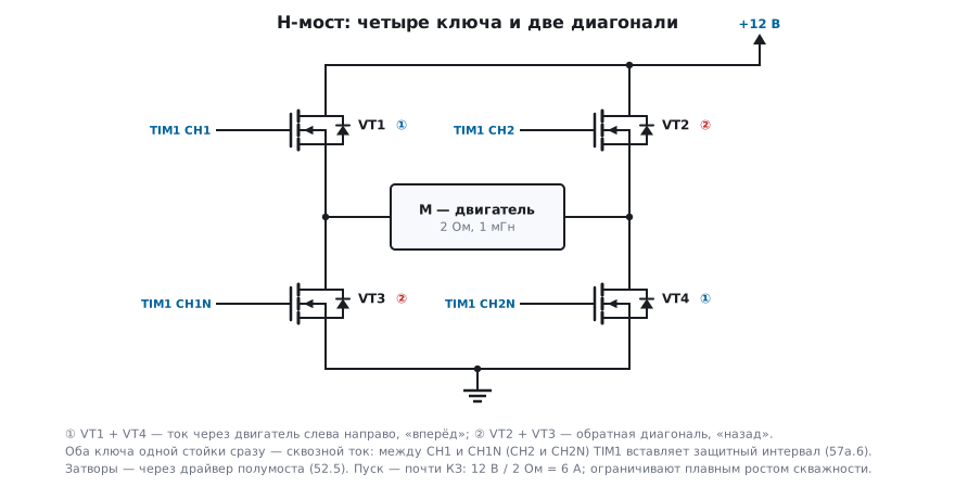
Model. Electrical part: U = R·i + L·di/dt + K·ω, where K·ω is the back EMF.
Mechanical part: J·dω/dt = K·i − b·ω. Take a notional 12 V motor with the
same winding as in section 57 (R = 2 Ω, L = 1 mH), K = 0.02 V·s/rad, rotor moment
of inertia J = 10⁻⁵ kg·m² and friction b = 10⁻⁶ N·m·s. The program integrates
the equations with a 1 µs step:
| Quantity | Result | Where it comes from |
|---|---|---|
| stall current | 6 A | U / R |
| peak start-up current | 5.78 A after 2.34 ms | the rotor has already started turning, back EMF rises |
| no-load speed | 597 rad/s = 5701 rpm | U·K / (R·b + K²) |
| time to 63 % of speed | 49.7 ms | mechanical time constant J·R / K² = 50 ms |
| no-load current | 0.03 A | only for friction |
The main conclusion: at start-up the motor is almost a short circuit. The start-up current is almost 200 times the no-load current, and the driver, the power supply and the traces are sized for it, not for the rated running current. Or it is limited — by ramping the duty cycle up smoothly.
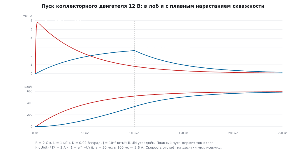
Soft start in the same model. The duty cycle rises from 0 to 100 % over 100 ms (PWM averaged): the current peak is 2.61 A at the end of the ramp, 2.2 times lower. While the voltage rises at a constant rate, the current only goes into accelerating the rotor: J·(dU/dt) / K² = 3 A, and it approaches this value with the mechanical time constant of 50 ms — by 100 ms it is just 2.6 A. The price is time: at 250 ms the speed is 585 rad/s versus 593 with a direct start.
Braking. Turn off all switches — the motor coasts down by itself. Short the winding with the two low-side switches — the back EMF drives a current through the shorted winding, and the motor brakes (the energy goes into heating the winding).
57а.3 Stepper: steps, half steps, microsteps
A bipolar stepper motor has two windings, A and B; the rotor aligns with the field they create. By changing the currents in a certain order you rotate the field — and the rotor follows it in steps. A typical motor is 1.8° per step, 200 steps per revolution.
| Mode | Currents (A, B) in order | Steps per revolution | What happens to torque |
|---|---|---|---|
| full step | (+,+) (−,+) (−,−) (+,−) | 200 | both windings always on: the field is √2 = 1.41 times stronger than with one |
| half step | (+,0) (+,+) (0,+) (−,+) (−,0) (−,−) (0,−) (+,−) | 400 | every other step only one winding works — torque "jumps" |
| 1/16 microstep | A = cos, B = sin, 16 levels per quarter | 3200 | the same field strength at any angle — smooth, quiet motion |
The 1/16 microstep table for a quarter turn of the field with an 8-bit current setpoint (255 is full current):
255/0 254/25 250/50 244/74 236/98 225/120 212/142 197/162 180/180
162/197 142/212 120/225 98/236 74/244 50/250 25/254 0/255
The numbers in the table are the winding current setpoint. It is held by a driver with current regulation (section 57е): the supply is several times higher than the rated winding voltage, and the switches limit the current at the set level in every PWM period. With simple voltage PWM the current has no time to rise at speed, torque drops — hence missed steps at high speed.
The field strength √(A² + B²) at all 17 points is from 0.998 to 1.002 of full:
rounding to 8 bits barely spoils it. In half-step mode it jumps
between 1 and 1.41 — hence jerks and noise.
Microstepping is not about positioning accuracy but about smoothness: a loaded rotor lags behind the field, and the intermediate positions hold more weakly than full steps.
57а.4 Stepper acceleration without square roots
A stepper cannot be started at full speed straight away — the rotor will not keep up
with the field and will start missing steps. It is accelerated at a constant acceleration α
(steps/s²). Then step n occurs at the moment tₙ = √(2n/α), and the interval
between steps is cₙ = tₙ − tₙ₋₁. Computing a square root on every step in an interrupt
is expensive; there is a recurrence formula:
/* при старте, один раз: интервал в тиках таймера, 8 бит дроби */
uint32_t c = (uint32_t)(F_TIMER * 0.676 * sqrt(2.0 / ALPHA) * 256.0);
TIMx->ARR = ((c + 128u) >> 8) - 1u;

/* в прерывании по шагу n = 1, 2, …: одно деление и одно вычитание */
uint32_t d = 4u * n + 1u;
c -= (2u * c + d / 2u) / d;
TIMx->ARR = ((c + 128u) >> 8) - 1u;
The root is computed once — for the first interval, and that one is taken with a correction of 0.676: without it the recurrence formula is badly wrong on the first steps.
Check at α = 2000 steps/s²:
| Step | Formula, s | Exact, s | Error |
|---|---|---|---|
| 2 | 0.0128262 | 0.0130986 | 2.08 % |
| 10 | 0.0051292 | 0.0051317 | 0.05 % |
| 100 | 0.0015852 | 0.0015851 | 0.003 % |
| 1000 | 0.0005001 | 0.0005001 | 0.003 % |
The worst error is at the second step, 2.08 %; by the tenth it is hundredths of a percent.
After 1000 steps the speed is 1999.4 steps/s against the exact 2000. The listing above
computes the same in whole ticks of a 1 MHz timer: at step 1000 it gives 500 ticks against the exact
500.1. The eight fraction bits in c are needed: without them rounding accumulates, and by step 1000
the error reaches 20 %.
57а.5 Brushless: Hall-sensor commutation
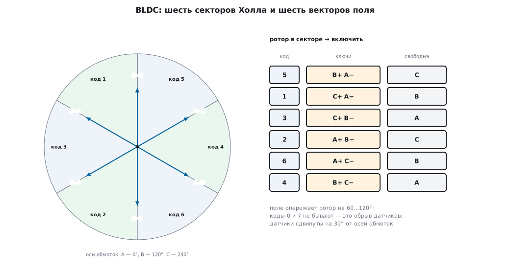
In a BLDC motor the windings are on the stator, the magnets are on the rotor, and the current must be switched by the controller. The simplest way is six steps: at any moment one phase is connected to "+", another to "−", the third is floating. Which ones is told by three Hall sensors placed 120° apart: their code is the sector number.
All angles here and below are electrical. In a motor with p pole pairs one electrical revolution is 1/p of a shaft revolution, and the six sectors repeat p times per revolution. On a motor with four pole pairs sensors "120° apart" may be placed 30° apart on the shaft, a "30°" shift is 7.5° of shaft rotation, and the shaft revolutions per second are the sector change rate divided by 6p.
The model in the program: the winding axes A, B, C are at 0°, 120°, 240°. A current "into X, out of Y" gives a field in the direction (axis X − axis Y) — six vectors 60° apart: A−C 30°, B−C 90°, B−A 150°, C−A 210°, C−B 270°, A−B 330°. For each rotor position (in 1° steps) the vector 90° ahead of the sector middle is chosen. The result:
| Sector | Hall C B A | Code | "+" | "−" | Floating |
|---|---|---|---|---|---|
| 0 | 1 0 1 | 5 | B | A | C |
| 1 | 0 0 1 | 1 | C | A | B |
| 2 | 0 1 1 | 3 | C | B | A |
| 3 | 0 1 0 | 2 | A | B | C |
| 4 | 1 1 0 | 6 | A | C | B |
| 5 | 1 0 0 | 4 | B | C | A |
What the model showed:
- the field leads the rotor by 60…120° in any position — the torque is always in one direction, maximum at 90°;
- codes 0 and 7 never occur: all sensors in the same state means a broken or shorted sensor wire. On seeing 0 or 7 the firmware must stop the motor;
- the sensors must be placed with a 30° shift from the winding axes. With the sensors right on the axes the sector boundary falls on the middle of a vector, and the lead wanders from 30 to 150° — the torque sags by half.
In real firmware the "code → switches" table is an array of 8 elements, indexed by the sensor code. The direction is reversed by shifting the table by three sectors.
57а.6 TIM1 for a motor
The STM32 does all of the above with the TIM1 timer (and TIM8 on the larger models), not in software:
Complementary outputs and dead time. Channels CH1…CH3 and CH1N…CH3N
drive the high-side and low-side switch of each half-bridge. Between turning
one off and the other on, the timer itself inserts a pause — the dead time,
set by the 8-bit DTG field of the BDTR register. The encoding has four ranges:
DTG[7:5] |
Interval |
|---|---|
| 0xx | DTG × tDTS |
| 10x | (64 + DTG[5:0]) × 2tDTS |
| 110 | (32 + DTG[4:0]) × 8tDTS |
| 111 | (32 + DTG[4:0]) × 16tDTS |
With tDTS = 125 ns (8 MHz) the function from the program gives the range boundaries 15875, 16000…31750, 32000…63000 and 64000…126000 ns — exactly the example from the reference manual. At 72 MHz (tDTS = 13.9 ns):
| Wanted | Code | Result |
|---|---|---|
| 100 ns | 0x08 | 111.1 ns |
| 500 ns | 0x24 | 500 ns |
| 1 µs | 0x48 | 1000 ns |
| 2 µs | 0x88 | 2000 ns |
| 5 µs | 0xCD | 5000 ns |
You cannot get more than 14 µs at 72 MHz (code 0xFF); longer values need the
CKD divider in CR1, which increases tDTS.
Break input BKIN. It is enabled by the BKE bit in BDTR, the polarity is BKP.
An active level on the input clears MOE in hardware and asynchronously, and all
outputs go to a safe state — without the processor. BKIN is
connected to a current comparator or to the driver fault signal.
Hall sensors. A second timer (TIM2…TIM5) with the TI1S bit in CR2 takes
the three sensors through an XOR onto the TI1 input: any change of the code
resets the counter and latches the time between changes — that is the
speed. Through TRGO the same timer can give TIM1 a COM commutation event,
and TIM1 switches the outputs to the next sector by itself.
Encoder — the encoder mode of a general-purpose timer (section 13.7).
57а.7 Field-oriented control in a nutshell
Six steps give torque with ripple: the field jumps by 60°. Smooth torque comes from field-oriented control (FOC): the currents of all three phases are sinusoidal, the field is always 90° ahead of the rotor. In every PWM period the firmware:
- measures the phase currents (two are enough — the sum of all three is zero);
- Clarke transform: three currents → two (α, β) in stationary axes:
α = ia,β = (ia + 2·ib) / √3; - Park transform: rotation by the rotor angle θ →
d = α·cosθ + β·sinθ,q = −α·sinθ + β·cosθ. In rotor axes the currents are constant:qcreates torque,dmust be zero; - two PI controllers (section 47) hold
d = 0andq= the setpoint; - inverse transforms and PWM on three phases.
The check in the program: three sinusoidal currents of amplitude 1 with the field 90°
ahead of the rotor, the rotor angle in steps of 5°. After Clarke and Park d does not
move away from zero and q from one by more than 7·10⁻¹⁶ — the precision
of double arithmetic. That is how it should be: in rotor axes the rotating field
stands still, and the controller is left working with constant quantities.
FOC needs the rotor angle — from an encoder or estimated from current and voltage — and a fast processor with a hardware FPU; for this ST has the G4 series and a ready-made motor control library.
57а.8 Pitfalls
The H-bridge burned out when reversing. Two switches on the same side ended up on at the same time. Dead time, and changing direction via the "everything off" state.
The driver goes into protection at start-up. The start-up current is many times the running current — in the example 5.8 A against 0.03 A at no load. Soft start with the duty cycle.
The stepper misses steps during acceleration. The acceleration is more than the motor can handle with its load. Lower α or more current.
The acceleration "jerks" at the beginning. The first interval without the 0.676 correction — the recurrence formula is badly wrong on the first steps.
The stepper heats up while standing still. The holding current is full. Reduce the current when stopped if the load allows.
The BLDC jerks and does not pick up speed. The sensors are shifted wrongly or the phase order is mixed up: the lead leaves 60…120°. You check it by turning the rotor by hand and comparing the codes with the table.
Sensor code 0 or 7. This never happens with working sensors — a break or a short. Stop the motor.
The dead time is "wrong". A DTG code above 0x7F is already another range with another multiplier. Calculate from the table, not as DTG × tDTS.
The TIM1 outputs are silent after a fault. BKIN fired and cleared MOE. Only
software can set it back (or it is set automatically if AOE is enabled).
57а.9 Summary
- Brushed — H-bridge and PWM; at start-up almost a short circuit: 6 A for a motor that takes 0.03 A at no load.
- Stepper — 200 steps per revolution at 1.8°; 1/16 microstepping gives 3200 positions and a field of constant strength (0.998…1.002).
- Acceleration — a recurrence formula with one square root for the whole ramp and a correction of 0.676 to the first interval; the error from the second step on is no more than 2.08 %.
- BLDC — six sectors by Hall codes 1…6; the field leads the rotor by 60…120° if the sensors are shifted 30° from the axes; codes 0 and 7 mean a fault.
- TIM1:
DTGin four ranges (up to 14 µs at 72 MHz),BKINclearsMOEin hardware, Hall sensors — throughTI1Sof a second timer. - FOC: Clarke and Park turn rotating currents into constant d and q.
Full source code
motor.c — the section's calculations on a PC: dead time, microstepping, acceleration, BLDC commutation, Clarke and Park, brushed-motor start-up.
/* Раздел 57а «Двигатели»: расчёты, которые прошивка делает сама.
 * Собирается обычным gcc на компьютере: gcc -O2 -o motor motor.c -lm && ./motor
 *
 *  1. защитный интервал TIM1: код DTG по времени и обратно (формула справочного руководства F1);
 *  2. шаговый двигатель: полный шаг, полушаг, микрошаг 1/16 — таблица токов;
 *  3. разгон шагового: интервалы между шагами без корня, рекуррентной формулой;
 *  4. BLDC: шестишаговая коммутация по датчикам Холла;
 *  5. преобразования Кларк и Парка;
 *  6. коллекторный двигатель: пуск от 12 В — ток и скорость по уравнениям;
 *  7. тот же пуск с нарастанием скважности за 100 мс — журнал dc_start.csv для рисунка.
 */
#include <math.h>
#include <stdint.h>
#include <stdio.h>
#include <stdlib.h>

/* ── 1. DTG ─────────────────────────────────────────────────────────────── */
/* Время защитного интервала для кода DTG при такте tDTS (нс), четыре диапазона. */
static double dtg_to_ns(uint8_t dtg, double tdts)
{
    if ((dtg & 0x80) == 0)
        return dtg * tdts;                              /* 0xx: DTG × tDTS */
    if ((dtg & 0xC0) == 0x80)
        return (64 + (dtg & 0x3F)) * 2 * tdts;          /* 10x: (64 + DTG[5:0]) × 2tDTS */
    if ((dtg & 0xE0) == 0xC0)
        return (32 + (dtg & 0x1F)) * 8 * tdts;          /* 110: (32 + DTG[4:0]) × 8tDTS */
    return (32 + (dtg & 0x1F)) * 16 * tdts;             /* 111: (32 + DTG[4:0]) × 16tDTS */
}

/* Наименьший код, дающий интервал не короче нужного. */
static int ns_to_dtg(double ns, double tdts)
{
    for (int d = 0; d < 256; d++) {
        /* внутри диапазона время растёт с кодом, между диапазонами — тоже */
        if (dtg_to_ns((uint8_t)d, tdts) >= ns - 1e-9)
            return d;
    }
    return -1;
}

/* ── 2. шаговый ─────────────────────────────────────────────────────────── */
static void stepper_tables(void)
{
    /* полный шаг, две обмотки включены: направление тока в A и B */
    static const int full[4][2] = {{+1, +1}, {-1, +1}, {-1, -1}, {+1, -1}};
    /* полушаг: между двумя «двумя включёнными» — одна включена */
    static const int half[8][2] = {{+1, 0}, {+1, +1}, {0, +1}, {-1, +1}, {-1, 0}, {-1, -1}, {0, -1}, {+1, -1}};
    printf("full:");
    for (int i = 0; i < 4; i++)
        printf(" %+d%+d", full[i][0], full[i][1]);
    printf("\nhalf:");
    for (int i = 0; i < 8; i++)
        printf(" %+d%+d", half[i][0], half[i][1]);
    printf("\n");
    /* микрошаг 1/16 на четверть оборота поля: ток A = cos, B = sin, 8 бит (255 — полный ток) */
    double min_mag = 1e9, max_mag = 0;
    printf("micro16:");
    for (int k = 0; k <= 16; k++) {
        double a = k * (M_PI / 2) / 16;
        int ia = (int)lround(255 * cos(a)), ib = (int)lround(255 * sin(a));
        double mag = sqrt((double)ia * ia + (double)ib * ib) / 255;
        if (mag < min_mag) min_mag = mag;
        if (mag > max_mag) max_mag = mag;
        printf(" %d/%d", ia, ib);
    }
    printf("\nmicro16_mag_min=%.4f max=%.4f\n", min_mag, max_mag);
    /* амплитуда тока при полном шаге с двумя обмотками — √2 от тока одной */
    printf("full_two_phase_mag=%.4f\n", sqrt(2.0));
    /* 1,8° на шаг → шагов на оборот; 1/16 — микрошагов */
    printf("steps_per_rev=%d micro16_per_rev=%d\n", (int)lround(360 / 1.8), (int)lround(360 / 1.8) * 16);
}

/* ── 3. разгон ──────────────────────────────────────────────────────────── */
/* Равноускоренное движение: n-й шаг случается в момент t_n = √(2n/α) (α — шагов/с²).
 * Интервал c_n = t_n − t_(n−1). Без корня: c_n = c_(n−1) − 2c_(n−1)/(4n+1), а первый
 * интервал берут с поправкой 0,676, чтобы ряд совпал с точным уже со второго шага. */
static void accel_profile(void)
{
    const double alpha = 2000.0;                        /* шагов в секунду за секунду */
    double c0 = 0.676 * sqrt(2 / alpha);
    double c = c0, t = 0, worst = 0;
    int worst_n = 0;
    printf("accel c0_exact=%.6f c0=%.6f\n", sqrt(2 / alpha), c0);
    for (int n = 1; n <= 1000; n++) {
        if (n > 1)
            c = c - 2 * c / (4 * (n - 1) + 1);
        t += c;
        double exact = sqrt(2.0 * n / alpha) - sqrt(2.0 * (n - 1) / alpha);
        double err = fabs(c - exact) / exact;
        if (n >= 2 && err > worst) { worst = err; worst_n = n; }
        if (n == 2 || n == 10 || n == 100 || n == 1000)
            printf("accel n=%d c=%.7f exact=%.7f err=%.3f%%\n", n, c, exact, 100 * err);
    }
    printf("accel worst_err_from2=%.2f%% at n=%d; after 1000 steps speed=%.1f steps/s (exact %.1f)\n",
           100 * worst, worst_n, 1 / c, alpha * sqrt(2 * 1000 / alpha));
}

/* То же в целых числах — так считает прерывание по шагу. Тики таймера 1 МГц, у интервала 8 бит
 * дроби: без них ошибка округления копится и к 1000-му шагу доходит до 20 %. */
static struct { uint32_t ARR; } tim_step, *TIMx = &tim_step;

static void accel_int(void)
{
    const double ALPHA = 2000.0;                                     /* шагов в секунду за секунду */
    const uint32_t F_TIMER = 1000000u;                               /* такт таймера шага */
    double worst = 0;
    uint32_t worst_n = 0;
/* при старте, один раз: интервал в тиках таймера, 8 бит дроби */
uint32_t c = (uint32_t)(F_TIMER * 0.676 * sqrt(2.0 / ALPHA) * 256.0);
TIMx->ARR = ((c + 128u) >> 8) - 1u;
    for (uint32_t n = 1; n < 1000; n++) {
/* в прерывании по шагу n = 1, 2, …: одно деление и одно вычитание */
uint32_t d = 4u * n + 1u;
c -= (2u * c + d / 2u) / d;
TIMx->ARR = ((c + 128u) >> 8) - 1u;
        double exact = (sqrt(2.0 * (n + 1) / ALPHA) - sqrt(2.0 * n / ALPHA)) * F_TIMER;
        double err = fabs(TIMx->ARR + 1.0 - exact) / exact;
        if (err > worst) { worst = err; worst_n = n + 1; }
        if (n + 1 == 2 || n + 1 == 10 || n + 1 == 100 || n + 1 == 1000)
            printf("accel_int n=%u ticks=%u exact=%.1f err=%.3f%%\n", (unsigned)(n + 1), (unsigned)(TIMx->ARR + 1u), exact, 100 * err);
    }
    printf("accel_int worst=%.2f%% at n=%u\n", 100 * worst, (unsigned)worst_n);
}

/* ── 4. BLDC ────────────────────────────────────────────────────────────── */
/* Датчики Холла через 120°: код HA|HB<<1|HC<<2. Для каждого из шести секторов — какая фаза
 * подключена к «+», какая к «−», какая свободна. Проверка: поле статора опережает ротор
 * на 60…120° в любом секторе — момент всегда в одну сторону. */
#define HALL_OFFSET 30.0

static void bldc_six_step(void)
{
    const char *ph = "ABC";
    int seen[8] = {0};
    double worst_lo = 1e9, worst_hi = -1e9;
    for (int deg = 0; deg < 360; deg++) {
        double th = deg + 0.5;                                   /* угол ротора, электрические градусы */
        /* датчики стоят через 120°, но сдвинуты на 30° от осей обмоток: иначе граница сектора
         * пришлась бы на середину вектора поля и опережение гуляло бы 30…150° */
        double r = fmod(th - HALL_OFFSET + 360, 360);
        int ha = r < 180;
        int hb = fmod(r - 120 + 360, 360) < 180;
        int hc = fmod(r - 240 + 360, 360) < 180;
        int code = ha | hb << 1 | hc << 2;
        seen[code]++;
        int sector = (int)(r / 60);                              /* 0…5 */
        /* поле статора — на 90° впереди середины сектора */
        double field = HALL_OFFSET + sector * 60 + 30 + 90;
        /* из шести векторов «+X −Y» выбираем ближайший к нужному полю. Оси обмоток A, B, C —
         * 0°, 120°, 240°; ток «в X, из Y» даёт поле по направлению (ось X − ось Y):
         * A−C 30°, B−C 90°, B−A 150°, C−A 210°, C−B 270°, A−B 330° */
        static const struct { int hi, lo; double ang; } vec[6] = {
            {0, 2, 30}, {1, 2, 90}, {1, 0, 150}, {2, 0, 210}, {2, 1, 270}, {0, 1, 330}};
        int best = 0;
        double bd = 1e9;
        for (int v = 0; v < 6; v++) {
            double d = fabs(fmod(vec[v].ang - field + 540, 360) - 180);
            if (d < bd) { bd = d; best = v; }
        }
        double lead = fmod(vec[best].ang - th + 720, 360);
        if (lead < worst_lo) worst_lo = lead;
        if (lead > worst_hi) worst_hi = lead;
        if (fmod(r, 60) < 1)
            printf("bldc sector=%d hall=%d%d%d code=%d +%c -%c float=%c\n", sector, hc, hb, ha, code,
                   ph[vec[best].hi], ph[vec[best].lo], ph[3 - vec[best].hi - vec[best].lo]);
    }
    printf("bldc codes_seen:");
    for (int c = 0; c < 8; c++)
        printf(" %d:%d", c, seen[c]);
    printf("\nbldc lead_min=%.1f lead_max=%.1f\n", worst_lo, worst_hi);
}

/* ── 5. Кларк и Парк ────────────────────────────────────────────────────── */
static void clarke_park(void)
{
    double worst_d = 0, worst_q = 0;
    for (int deg = 0; deg < 360; deg += 5) {
        double th = deg * M_PI / 180;
        /* три фазных тока амплитудой 1, ротор под углом th, ток «по q» — на 90° впереди */
        double ia = cos(th + M_PI / 2), ib = cos(th + M_PI / 2 - 2 * M_PI / 3), ic = cos(th + M_PI / 2 + 2 * M_PI / 3);
        double alpha = ia;                                         /* Кларк, амплитудно-инвариантный */
        double beta = (ia + 2 * ib) / sqrt(3.0);
        double d = alpha * cos(th) + beta * sin(th);               /* Парк */
        double q = -alpha * sin(th) + beta * cos(th);
        if (fabs(d) > worst_d) worst_d = fabs(d);
        if (fabs(q - 1) > worst_q) worst_q = fabs(q - 1);
        (void)ic;
    }
    printf("park max|d|=%.2e max|q-1|=%.2e\n", worst_d, worst_q);
}

/* ── 6. коллекторный: пуск ──────────────────────────────────────────────── */
static void dc_motor(void)
{
    const double V = 12, R = 2, L = 1e-3, K = 0.02, J = 1e-5, B = 1e-6;
    double i = 0, w = 0, dt = 1e-6, t = 0, ipk = 0, t_ipk = 0, t63 = -1;
    double w_ss = V * K / (R * B + K * K);                        /* установившаяся скорость без нагрузки */
    while (t < 0.5) {
        double di = (V - R * i - K * w) / L;
        double dw = (K * i - B * w) / J;
        i += di * dt;
        w += dw * dt;
        t += dt;
        if (i > ipk) { ipk = i; t_ipk = t; }
        if (t63 < 0 && w >= 0.632 * w_ss) t63 = t;
    }
    printf("dc stall=%.2f A ipk=%.2f A at %.2f ms; w_ss=%.1f rad/s = %.0f rpm; t63=%.1f ms; tau_m=%.1f ms; i_end=%.3f A\n",
           V / R, ipk, t_ipk * 1e3, w_ss, w_ss * 60 / (2 * M_PI), t63 * 1e3, J * R / (K * K) * 1e3, i);
}

/* ── 7. пуск «в лоб» и плавный: скважность от 0 до 100 % за 100 мс (ШИМ усреднён) ──
 * Журнал dc_start.csv — для рисунка: время, мс; ток и скорость при пуске в лоб; то же при плавном. */
static void dc_soft_start(void)
{
    const double V = 12, R = 2, L = 1e-3, K = 0.02, J = 1e-5, B = 1e-6, RAMP = 0.1;
    double i1 = 0, w1 = 0, i2 = 0, w2 = 0, dt = 1e-6, ipk2 = 0, t_ipk2 = 0;
    FILE *f = fopen("dc_start.csv", "w");
    for (long n = 0; n <= 250000; n++) {
        double t = n * dt;
        if (f && n % 500 == 0)
            fprintf(f, "%.1f,%.4f,%.2f,%.4f,%.2f\n", t * 1e3, i1, w1, i2, w2);
        double u2 = V * (t < RAMP ? t / RAMP : 1.0);
        double di1 = (V - R * i1 - K * w1) / L, dw1 = (K * i1 - B * w1) / J;
        double di2 = (u2 - R * i2 - K * w2) / L, dw2 = (K * i2 - B * w2) / J;
        i1 += di1 * dt;
        w1 += dw1 * dt;
        i2 += di2 * dt;
        w2 += dw2 * dt;
        if (i2 > ipk2) { ipk2 = i2; t_ipk2 = t + dt; }
    }
    if (f)
        fclose(f);
    printf("dc_soft ramp=100 ms ipk=%.2f A at %.1f ms; w_250ms=%.1f rad/s (direct %.1f)\n", ipk2, t_ipk2 * 1e3, w2, w1);
}

int main(void)
{
    const double tdts72 = 1e3 / 72.0;                              /* нс: такт 72 МГц, CKD = 00 */
    const double tdts8 = 125.0;
    printf("dtg8 max: %.0f %.0f %.0f %.0f %.0f %.0f %.0f\n", dtg_to_ns(0x7F, tdts8), dtg_to_ns(0x80, tdts8),
           dtg_to_ns(0xBF, tdts8), dtg_to_ns(0xC0, tdts8), dtg_to_ns(0xDF, tdts8), dtg_to_ns(0xE0, tdts8), dtg_to_ns(0xFF, tdts8));
    int ns_list[] = {100, 500, 1000, 2000, 5000};
    for (unsigned k = 0; k < sizeof ns_list / sizeof ns_list[0]; k++) {
        int d = ns_to_dtg(ns_list[k], tdts72);
        printf("dtg72 want=%d ns -> DTG=0x%02X = %.1f ns\n", ns_list[k], d, dtg_to_ns((uint8_t)d, tdts72));
    }
    printf("dtg72 max=%.0f ns\n", dtg_to_ns(0xFF, tdts72));
    stepper_tables();
    accel_profile();
    accel_int();
    bldc_six_step();
    clarke_park();
    dc_motor();
    dc_soft_start();
    return 0;
}
Next: section 57б "Motor current: shunt, amplifier, sampling at the right moment of the PWM" — where to put the shunt, how to amplify its signal and at which moment of the PWM period to take the sample.