 Embedded HandbookApps
173. Power protection: reverse polarity, fuse, transient suppressor
A microcontroller pin is protected with a resistor and a clamp — that is section 62. This section is about the power input of the whole board: what to put there so that swapped wires, a short circuit and a transient in the wiring do not burn the device. Diodes are covered in section 169, switches in 171 and 172; now we build circuits from them.
All the numbers below come from ngspice models: a 12 V supply, a 12 Ω load (about 1 A).
Terms used in the documentation
Term Meaning reverse polarity protection protection against swapped supply wires ideal diode / active rectifier a transistor acting as a low-drop diode high-side / low-side protection protection in the positive / negative wire crowbar (shunt diode) a diode across the input that shorts it on reverse polarity fuse / resettable fuse (PPTC) a one-time fuse / a self-resetting one hold current / trip current current the fuse carries indefinitely / current at which it opens transient voltage suppressor (TVS) a diode that clamps voltage transients breakdown voltage (VBR) voltage at which the suppressor starts to conduct clamping voltage (VC) suppressor voltage at a given pulse current peak pulse power / energy power / energy the suppressor can absorb in a pulse dynamic resistance the slope of voltage vs current above breakdown
173.1 Reverse polarity: four circuits
It is easy to swap plus and minus: a screw terminal, an unkeyed connector, a power adapter from another device. What you can put at the input:
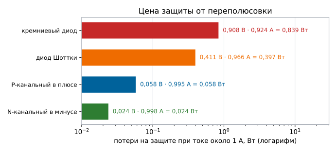
| Circuit | Drop at 1 A | Losses | At reverse polarity |
|---|---|---|---|
| silicon diode in series | 0.908 V | 0.839 W | 7 nA |
| Schottky diode in series | 0.411 V | 0.397 W | 30 µA |
| P-channel in the positive wire | 57.9 mV | 57.6 mW | 13 pA |
| N-channel in the negative wire | 23.8 mV | 23.8 mW | 13 pA |
A diode is the simplest solution and the most expensive in losses: almost a volt of drop and almost a watt of heat per amp. A Schottky is twice as good in drop, but it has a large reverse current (section 169.3), and when hot — milliamps.
A transistor as a diode (an "ideal diode") is the same switch from section 171, connected so that the body diode faces against the reverse current:
- P-channel in the positive wire: drain to the source of power, source to the load, gate through 100 kΩ to ground. With correct polarity the gate is at −12 V relative to the source, the channel is on, the drop is 57.9 mV. With reverse polarity the gate and source are equal, the channel is off, the body diode is reverse-biased.
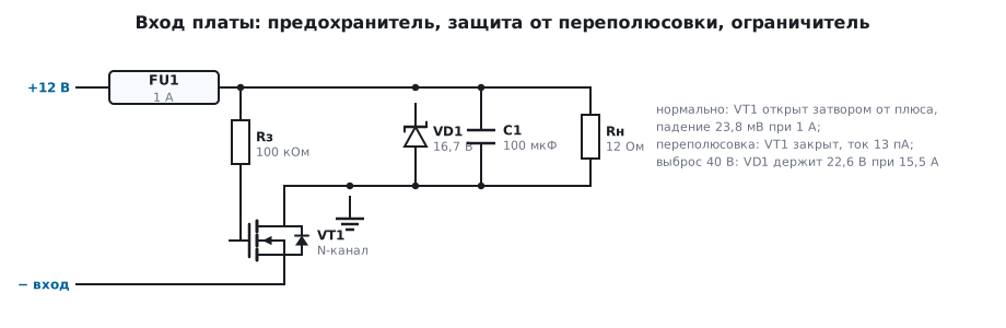
- N-channel in the negative wire: drain to the supply's minus, source to the board ground, gate through 100 kΩ to plus. Like the P-channel one, it is placed "back to front": the body diode conducts in the working direction, and at reverse polarity it is reverse-biased. The drop is half as large — 23.8 mV, because an N-channel transistor in the same package has a lower channel resistance. The downside of the circuit: the board ground and the supply minus are separated by the transistor, and any external ground connection (USB, a debugger, a sensor with a common ground) bypasses it.
The gate needs protection too. It is pulled through 100 kΩ to the opposite wire, so the gate-source voltage equals the supply voltage. For power transistors the limit is usually ±20 V, for small ones in SOT-23 ±12 and ±8 V (section 172): 12 V fits with margin only into the first, and a 24 V supply exceeds even that. The transient from 173.3 is dangerous in different ways: a short one, of 50 µs, the gate cannot follow — its capacitance charges through 100 kΩ for hundreds of microseconds, and in the model the gate-source voltage reaches only 13.4 V for the P-channel and 13.9 V for the N-channel; a transient 3 ms long brings it to 22.6 V for both. That is why a Zener diode of 10…15 V is placed between gate and source, and the 100 kΩ resistor limits its current: with a 12 V Zener the same model gives 12.0 V.
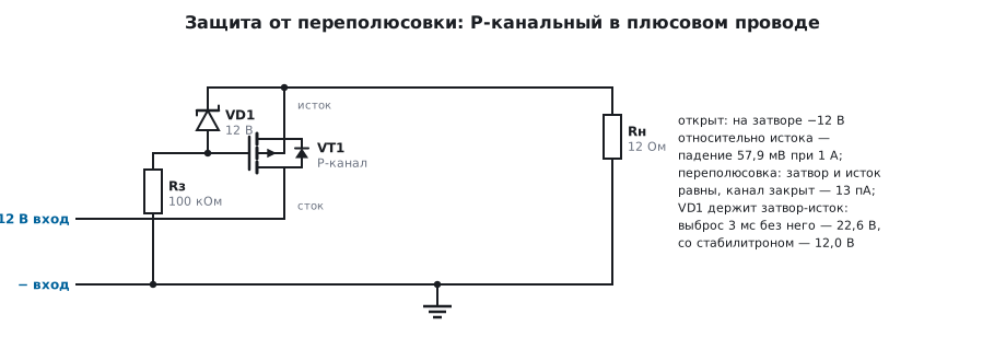
Hence the choice: a board with an isolated supply — N-channel in the negative wire; a board whose ground is shared with the outside world — P-channel in the positive wire.
173.2 A diode across the input and a fuse
A fifth circuit: the diode is placed across the input, cathode to plus, with a fuse in front of it. At normal polarity the diode is off and does not interfere: with a source internal resistance of 0.5 Ω and a 0.05 Ω fuse the load gets 0.956 A, and 47.8 mV drops across the fuse.
At reverse polarity the diode conducts and shorts the input: in the model 18.6 A flows through the fuse, and it blows. The circuit protects both against reverse polarity and against a short circuit in the load, but:
- a fuse is one-time, and a resettable one (PPTC) does not trip instantly — it takes hundreds of milliseconds;
- the diode must survive the trip current of the fuse;
- while the fuse is intact, the input stays shorted across the source.
This circuit is popular in automotive supplies and in cheap power adapters: it adds no losses in normal operation.
173.3 A transient at the input: the suppressor
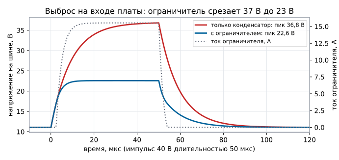
Transients come to the board through the wiring: a relay coil switched off, a nearby load jerked. A model of such a short transient: a 12 V source with an internal resistance of 1 Ω, a 40 V pulse of 50 µs arrives at the input, the board has 10 µF and a 12 Ω load.
| What is at the input | Peak voltage | Suppressor current | Energy in it |
|---|---|---|---|
| only a 10 µF capacitor | 36.8 V | — | — |
| capacitor and suppressor | 22.6 V | 15.5 A | 16.1 mJ |
Without a suppressor the bus reaches 36.8 V — enough to kill a 30 V regulator and everything after it. With a suppressor it is 22.6 V.
⚠️ The clamping voltage is higher than the breakdown voltage. The suppressor in the model has a breakdown of 16.7 V and a dynamic resistance of 0.35 Ω, and at a current of 15.5 A it has 16.7 + 0.35 · 15.5 = 22.1 V across it. In the documentation this is a separate row, "clamping voltage at a given peak pulse current", and that is the row to choose by, not the breakdown voltage.
How to choose: the working (stand-off) voltage of the suppressor is above the maximum supply (otherwise it leaks and heats up in normal operation), the clamping voltage is below the maximum voltage of what you protect, and the pulse energy has margin over the expected transient.
An automotive input is a separate story. Disconnecting the alternator under load (load dump) is a transient lasting not microseconds but fractions of a second, and it carries orders of magnitude more energy than 16 mJ; it is handled by the protection in the alternator itself or a separate circuit, not by a suppressor at the board. And the suppressor from the model is no good for a car anyway: during a jump start from an external 24 V battery it will conduct, and even through the model's 1 Ω it will have 18.5 V at 4.0 A — 74 W, not as a pulse, but for the whole start. On an automotive input the working voltage of the suppressor is chosen above 24 V, and the regulator after it is rated for its clamping voltage.
173.4 What to put at the board input
The order from the connector inward:
- Fuse — against a short circuit and against the consequences of reverse polarity. A resettable one is convenient where the board is hard to reach, but it is slow and changes its resistance after tripping.
- Reverse polarity protection — a transistor if losses matter, a diode if simplicity matters.
- Suppressor — against transients in the wiring; for boards in a car and in industrial wiring it is mandatory. A unidirectional one is placed after the reverse polarity protection: before it, with swapped wires, it will conduct like the diode from 173.2 and blow the fuse; otherwise use a bidirectional one.
- Bulk capacitor and decoupling — section 167: an electrolytic or polymer capacitor at the input, ceramics at the regulator.
Then comes the regulator (section 55), and from it the board supply. In addition: an RC or LC filter for the analog part (section 168.2).
173.5 Pitfalls
The board works, but the input diode runs hot. A silicon diode at one amp gives 0.9 V and almost a watt; a transistor in the same role gives 58 mV.
The "ideal diode" does not protect. The transistor is connected with drain and source swapped: the body diode conducts the reverse current regardless of the gate (section 171.6).
An N-channel in the negative wire stopped protecting after a debugger was connected. The board ground got connected to the external one through the cable — the transistor is bypassed.
The regulator burned out although a suppressor was fitted. It was chosen by the breakdown voltage: at the pulse current the clamping voltage is noticeably higher — 22.6 V versus 16.7 V in the model.
The protection transistor failed after a transient. The gate had no Zener diode: a long transient raised the gate-source voltage above ±20 V.
The suppressor heats up in normal operation. The working voltage was chosen too close to the supply — it leaks.
A resettable fuse did not save the transistor. It trips in hundreds of milliseconds, while a junction fails in microseconds: it protects against fire, not against burnout.
173.6 Summary
- Reverse polarity: a silicon diode — 0.908 V and 0.839 W at 1 A, a Schottky — 0.411 V and 0.397 W, P-channel — 57.9 mV, N-channel in the negative wire — 23.8 mV.
- At reverse polarity the transistors hold a leakage current of 13 pA, a Schottky 30 µA.
- A diode across the input with a fuse: in normal operation 47.8 mV across the fuse, at reverse polarity 18.6 A through it — the fuse blows.
- A 40 V transient of 50 µs: without a suppressor the bus reaches 36.8 V, with one 22.6 V at a current of 15.5 A and an energy of 16.1 mJ; clamping voltage = breakdown plus the drop across the dynamic resistance.
- The gate of an "ideal diode" gets a 10…15 V Zener diode: a transient 3 ms long brings the gate-source voltage to 22.6 V, with a 12 V Zener 12.0 V.
Next: section 173а "Power loss" — how many milliseconds the board has when the input is gone, and what to save in them.