 Embedded HandbookApps
204. Reliability: margins, aging and in-house testing
The device is assembled (199), it powers up (200), it passes the line test (201), it is calibrated (202) and it survived interference (203). One question is left that no test bench answers with a single measurement: how long will it live? You cannot "solder in" reliability at the end. It is built from the margins designed into the circuit, from how fast specific parts age, and from tests that find the weak spot before the customer does. All of this is possible without a lab: the arithmetic of aging fits on a sheet of paper, and a burn-in at elevated temperature fits in a box with a lamp.
The numbers in this section come from _verify/rel204/aging_calc.py
and therm_calc.py; Flash endurance, retention and thermal resistances
come from the F103 and F407 datasheets in the packs (extracted by flash_ds.py); the settings-write
model wear_budget.c was built with gcc 12 in the stm-lab:1 image
and run, and the save counts are taken from its output.
What it is called in the documentation
Original Meaning mean time between failures (MTBF) average operating time between failures failure rate, FIT how often parts fail; 1 FIT is one failure per billion device-hours bathtub curve failure curve shaped like a bathtub: early failures, plateau, wear-out infant mortality early failures in the first hours of operation wear-out failures from wear: the part's life is used up acceleration factor how many times a harsh condition speeds up aging power cycling repeated power on and off elevated temperature soak powered hold at elevated temperature no fault found (NFF) the fault was not confirmed when the return was examined
204.1 Reliability in numbers: MTBF and the bathtub curve
Over its life, a device's failures fall on a curve shaped like a bathtub. On the left are early failures: hidden manufacturing defects (a cold solder joint, a crack in a ceramic part, a weak die) show up in the first hours and days. The bottom is normal operation: failures are rare and random. On the right is wear-out: parts reach the end of their life, and the failure rate grows month by month.
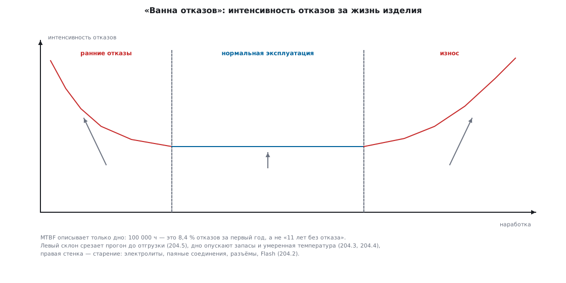
Mean time between failures (MTBF) describes only the bottom. MTBF = 100000 h
does not mean "the device lives 11 years". It means "at the bottom of the bathtub, failures happen on average
once every 100000 hours". For a single device this is a probability: the chance of failing
in the first year is 1 − exp(−8760/100000) = 8.4 %; out of a hundred devices
at customers, about eight will fail in a year (aging_calc.py). Service
life is set not by MTBF but by the right wall of the bathtub, the fastest-aging
part: a device with a calculated MTBF of decades and an electrolytic capacitor next to a hot
regulator will be dead in three years.
Failure rates add up: a device of 100 parts at 50 FIT each
is 5000 FIT, so MTBF is 10⁹/5000 = 200000 h, about 23 years. This has two
consequences. Every extra part adds to the denominator: a circuit with half the
parts is twice as reliable, all else being equal. And one bad component
spoils the whole sum: FIT values of parts differ by orders of magnitude, so you should hunt
not for "reliability in general" but for the worst line in the list, and that is what
the next subsection is about.
⚠️ Early failures are cut off before shipping. The left slope of the bathtub is a defect that has almost shown itself: it will appear in the first few tens of hours of operation. A powered burn-in of assembled devices over the weekend, at elevated temperature (204.5), moves these failures from the customer's site to your desk. That is why "run it for a week before shipping" is not superstition but moving the point of failure.
204.2 What ages first
It is not "the device in general" that ages. Specific parts age, each by its own mechanism.
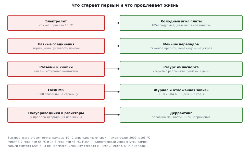
Electrolytic capacitors are almost always first: the electrolyte
dries out, and the drying rate doubles every 10 °C. The rated 2000 h
at 105 °C turn into (aging_calc.py, details in 167.6):
| Temperature inside the enclosure | Life |
|---|---|
| 105 °C | 2000 h |
| 65 °C | 32000 h, 3.7 years |
| 45 °C | 128000 h, 14.6 years |
The 10 °C rule is the main formula of this section: ten degrees cooler means twice as long a life. It works the other way too: an electrolytic capacitor pressed against a hot regulator ages two to four times faster than its neighbor in a cool corner of the board.
Solder joints fatigue from thermal cycles. The board and the part expand
differently: for a chip package 3.2 mm long, with a difference in expansion
coefficients of 10 ppm/°C and a swing of 60 °C, the ends "walk" by 1.9 µm per cycle
(aging_calc.py). That is microns, but every day of switching on and off is a cycle,
and over the years the solder accumulates fatigue cracks: the classic failure
"works until it cools down". The cure is smaller temperature swings (204.4)
and mechanics: fix heavy parts in place, and do not put large leadless packages
near a flexing edge of the board (see ceramic cracks in 199.9).
Connectors and buttons wear out with cycles: the contact plating wears off, resistance grows, and bounce appears where there was none. The rated life, from tens to thousands of cycles, is given by the manufacturer in the datasheet; compare it with how the product is really used: a connector that is plugged ten times a day collects 3650 cycles a year.
The microcontroller's Flash is the only aging part inside the chip,
and its endurance is documented. The F103 and F407 datasheets give the same
numbers (flash_ds.py extracts them from the pack PDFs):
| Parameter (F1 and F4: same numbers) | Guaranteed |
|---|---|
| page or sector erase cycles | 10000 |
| retention after 1 thousand cycles at 85 °C | 30 years |
| retention after 1 thousand cycles at 105 °C | 10 years |
| retention after 10 thousand cycles at 55 °C | 20 years |
Read the table as a story of aging: worn Flash forgets faster (after 10 thousand cycles retention is measured at only 55 °C), and hot Flash forgets three times faster: 30 years at 85 °C versus 10 years at 105 °C, that is ×1.7 for every 10 °C, close to the 10 °C rule. Firmware written once is not affected by this; a settings page that is erased every day is affected a lot (204.6).
204.3 Margins: derating
A margin means running a part at a fraction of its rated limit. This is not over-caution: near the limit, degradation is nonlinear, and every bit of margin buys years. Typical fractions and why they are what they are:
| Parameter | Typical fraction | Why exactly this much |
|---|---|---|
| capacitor voltage | 50 % for tantalum, 70–80 % for ceramic and electrolytic | a tantalum capacitor fails as a short circuit (167.6); the margin covers a spike that got past the clamp (173.3) |
| resistor power | 50 % | the rating is given at 25 °C in open air; inside an enclosure at 60 °C only half of it is left anyway (166) |
| current of switches and diodes | 50–70 % | heating grows as the square of current: 70 % of the current is half the power |
| temperature of dies and electrolytes | 20–30 °C below the limit | the 10 °C rule: 20 °C cooler means four times longer life |
The justification is always one of two things. Either the square: power and heating
grow as I² and U², so a fraction of 0.7 in current or voltage is
already half in heat. Or the aging exponent: service life drops
by half for every 10 °C, so a temperature margin is the cheapest
way to buy years: it needs no other parts, only a different
placement on the board.
⚠️ The margin goes into the parts list, not into the post-mortem of a return. The fraction is calculated not from the "normal" mode but from the worst case: maximum mains voltage, maximum load, summer, a closed enclosure. A 16 V capacitor on a 12 V bus looks like a 25 % margin until you remember the spike up to 14.5 V from battery charging: then only 9 % is left.
204.4 Heat: temperature rise from thermal resistance
Temperature multiplies all aging mechanisms, so the thermal
calculation is the first reliability calculation. The datasheet gives the thermal
resistance from junction to ambient, θJA in °C/W, and the temperature rise is calculated in one
line: T_junction = T_ambient + P · θJA.
| Package | θJA, F103 | θJA, F407 |
|---|---|---|
| LQFP48 7×7 mm | 55 °C/W | — |
| LQFP64 10×10 mm | 45 °C/W | 46 °C/W |
| LQFP100 14×14 mm | 46 °C/W | 43 °C/W |
| LQFP144 20×20 mm | — | 40 °C/W |
Let us calculate the worst case from the datasheets (therm_calc.py). An F103 in LQFP48
at 72 MHz with all peripherals draws no more than 50 mA: P = 3.3 V × 50 mA =
0.165 W, temperature rise 0.165 × 55 = 9.1 °C. An F407 in LQFP100
at 168 MHz draws up to 117 mA: P = 0.386 W, temperature rise 0.386 × 43 =
16.6 °C. In a room nobody cares. But put the device
in a cabinet in the sun, where the air around the board is 85 °C, and the F407 die will be
at 102 °C with a limit of 105 °C: there is no margin, and that is before counting its neighbors.
Practical consequences:
- Calculate from the air near the board, not from the room. A closed enclosure without ventilation is warm by itself: inside it is tens of degrees above the room if watts are dissipated in it.
- The MCU is rarely the main heater. A linear regulator 12 → 3.3 V at
100 mA dissipates 0.87 W, which is 2.3 times more than the whole F407 and 5
times more than the F103 (
therm_calc.py); choosing a converter is covered in section 55. Drivers and power switches heat up too, and they heat their neighbors: an electrolytic capacitor next to them ages by the 10 °C rule. - A heatsink and airflow are needed when the temperature rise is counted no longer in degrees but in tens of degrees: θJA in still air fundamentally cannot be reduced in software. A heatsink lowers the thermal resistance of the hot part, a fan lowers it for the whole box; but every fan is itself a part with a limited life, and its failure also goes into the calculation.
🔧 Temperature rise is measured, not only calculated. The built-in die temperature sensor (14.7) is read in two lines: read it right after a cold start and after half an hour of operation in the closed enclosure; the difference is your real temperature rise plus the heating of the box. Hot spots on the board are found with a thermistor or a DS18B20 (96) pressed against the parts, or with a finger, but a finger does not keep a log.
204.5 In-house testing: burn-in, temperature, cycles
Home tests do not replace a lab, but two benches made from things at hand find most weak spots.
Burn-in at elevated temperature. A plywood box, an incandescent
lamp or a heating element with a thermostat, a thermometer, and the devices run
for a week at 60 °C under normal load. Elevated temperature is
a time accelerator: by the 10 °C rule, going from 25 → 60 °C speeds up
chemical aging 11 times (the more accurate exponential model
with a typical activation energy of 0.7 eV gives 17 times, the same order of magnitude,
aging_calc.py). A week of such burn-in is about 2.6 months of life
at room temperature: it pulls out almost all early failures (204.1),
and along the way it reveals hangs that happen only
in a warm device.
Power cycles. A relay with a timer switches the power:
a 30-second cycle gives 2880 cycles per day, twenty thousand per week
(aging_calc.py). This checks three things at once: the inrush current at
power-up, correct firmware startup from any state,
and "on, warmed up, off, cooled down" thermal cycles in miniature.
The device must not just power up but reach the working state
every time, and this is checked by firmware with a log (204.6),
not by a person at the bench.
Honest caveats: what a home bench will and will not show:
| Bench | Will show | Will NOT show |
|---|---|---|
| a week at 60 °C | early failures, "hangs when warm", weak electrolytic capacitors | moisture, vibration, rated life |
| power cycles | inrush current, startup from any state | life of connectors and buttons: they are cycled separately |
| both together | gross design holes | statistics: you cannot measure MTBF on three units |
⚠️ Three devices over a month are not statistics. No failures in three units proves only the absence of gross defects. Real reliability statistics are gathered where the devices live, at the customers; so that they are not lost, every device carries a log (204.6), and every return is analyzed (204.7).
204.6 Firmware and service life
Firmware does not age, but it manages three things that either age or save the day.
A watchdog (12) is mandatory in a product: at the bottom of the bathtub failures are rare but random, and a hang once every six months across a thousand customers means five hung devices every day. The IWDG turns them into an unnoticed restart, and the reset cause flags (12.4) turn them into a log line.
Settings writes need a wear budget. A Flash page has 10000
erase cycles (204.2), and naive firmware spends them without anyone noticing. The model
wear_budget.c: the user adjusts brightness every 5 minutes for 16 hours
a day, which gives 192 changes per day:
запись при каждом изменении  192 зап./сут; без журнала    52 дн; журнал 11.8:   3333 дн =   9.1 лет
отложенная запись (прогон)   15 зап./сут; без журнала   666 дн; журнал 11.8:  42666 дн = 116.9 лет
Writing "immediately and to one page" kills the device in 52 days. A journal on two pages (11.8) stretches the life 64 times, to 9.1 years. Deferred writing adds another order of magnitude: settings are marked as changed, written no more often than once an hour, and on power loss they are written immediately from the PVD brown-out detector interrupt (10.7):
void cfg_mark_dirty(uint32_t now) /* вызывать при каждом изменении */
{
if (!dirty) {
dirty = 1;
dirty_since = now;
}
}
void cfg_tick(uint32_t now) /* раз в секунду из главного цикла */
{
if (dirty && now - dirty_since >= WRITE_HOLDOFF_S) {
cfg_save(¤t);
dirty = 0;
}
}
void cfg_power_down(void) /* по прерыванию PVD: питание уходит */
{
if (dirty) {
cfg_save(¤t); /* дописать, пока держит конденсатор */
dirty = 0;
}
}
In the run, a day gave 15 saves instead of 192, and the journal lasts 116.9 years: Flash endurance is no longer the shortest line in the aging list. Where to store calibration coefficients is covered in 202.5; they do not need deferred writing: they are written once on the line.
The device's failure log. A line about the release of each board is already in your production log (201.7); the device should keep a matching log about its own life: reset counters by cause, operating hours, maximum die temperature, configuration check triggers (203.5). It is written rarely, once a day and on events, so it uses almost no endurance, and when the device comes back it turns "does not work" into a diagnosis (204.7).
204.7 Failure analysis: returns and "cannot reproduce"
A return is the most expensive and the most informative unit of a batch: a device that found a weak spot in the design for you. How to handle it:
- Record first, repair later. Photos, external inspection, reading the failure log and reset flags, all before the first soldering: repair destroys evidence. Half of the causes are visible by eye, from traces of overheating, corrosion and mechanical damage.
- "Cannot reproduce" is not a verdict but a symptom. A device that works on the desk was not returned for no reason. Look at the log (resets? maximum temperature?), ask about the environment (a cabinet, the sun, a contactor behind the wall (203)) and heat it on the 204.5 bench: intermittent failures are most often caused by temperature or interference.
- Look for what returns have in common instead of repairing them one by one. The serial number leads to the release log (201.7): the same batch of parts? the same board revision? the same calibration numbers at the edge of tolerance? Three returns with the same failure are not three accidents but one systematic defect.
- The method for finding the cause on the board is the same as at first power-up (200.7): from the power supply to the chip, splitting the circuit in half.
A closed analysis is a line in the log: cause, batch, what was changed. The list of such lines over a year is an honest map of the product's weak spots, and the next board revision is made from it, not from gut feeling.
204.8 Pitfalls
The device passed a week-long burn-in, and returns started a year later. Burn-in cuts off the left slope of the bathtub; it does not cancel wear-out: a week at 60 °C is only ~2.6 months of life at 25 °C. Margins (204.3) and cool electrolytic capacitors work against wear-out, not burn-in.
The MTBF calculation says 23 years, but the electrolytic capacitor dried out in four. MTBF describes the bottom of the bathtub; service life is set by the fastest part on the right wall: a 2000-hour electrolytic capacitor at 65 °C inside the enclosure lasts 3.7 years, and no MTBF will change that.
Settings stopped saving after two months. Every change is written to the same page: 192 writes per day eat up 10000 erase cycles in 52 days. A journal on two pages and deferred writing (204.6) give years instead of weeks.
Works on the desk, hangs in a cabinet in summer. The F407's own 16.6 °C of temperature rise plus the hot air of the cabinet put the die at its limit. Calculate from the ambient temperature near the board and measure with the built-in sensor (14.7), not with a thermometer on the wall.
A "cannot reproduce" return was closed as working. Without a failure log the device is mute: the cause stayed at the customer's site and will come back as the next return. Reset counters, operating hours and maximum temperature are written into every device before shipping (204.6).
The margin was calculated from the "normal" mode. A 16 V capacitor on a 12 V bus has a 25 % margin until charging raises the bus to 14.5 V. Derating fractions (204.3) are calculated from the worst case: maximum mains voltage, summer, a closed enclosure.
204.9 Summary
- The bathtub curve: burn-in before shipping cuts off early failures, MTBF describes the bottom, and the fastest-aging part sets the right wall. MTBF 100000 h means 8.4 % failures in the first year, not "11 years without failure"; FIT values add up: 100 parts at 50 FIT give an MTBF of 200000 h.
- The 10 °C rule: ten degrees cooler means twice as long a life. An electrolytic capacitor rated 2000 h/105 °C lasts 3.7 years at 65 °C and 14.6 years at 45 °C; thermal cycles flex solder joints by microns per cycle, causing fatigue.
- F1 and F4 Flash: 10000 erase cycles; retention 30 years at 85 °C after 1 thousand cycles, 10 years at 105 °C, 20 years at 55 °C after all 10 thousand; worn and hot Flash forgets faster.
- Derating: 50 % of power, 50–80 % of voltage, 20–30 °C
below the limit; the justification is the square (
I²,U²) and the aging exponent. - Temperature rise = P·θJA: F103 in LQFP48 is +9.1 °C, F407 in LQFP100 is +16.6 °C; with 85 °C around the F407 that is 102 °C out of the allowed 105. The main heaters are regulators and switches (0.87 W for a linear 12 → 3.3 V regulator at 100 mA).
- In-house testing: a week at 60 °C ≈ ×11 acceleration (≈ 2.6 months of life), a relay cycler gives 2880 power-ups per day; they find holes but do not measure MTBF: statistics come from customers through the failure log.
- Firmware: a watchdog plus a failure log; write settings only through a journal
and deferred: 52 days → 9.1 years → 116.9 years in the
wear_budget.cmodel.
Full source code
wear_budget.c: Flash wear budget for settings, three write strategies.
/* wear_budget.c — раздел 204.6: бюджет ресурса Flash под настройки.
*
* Модель суток: пользователь крутит яркость каждые 5 минут по 16 часов
* в день (192 изменения). Сравниваются три стратегии записи и считается,
* на сколько лет хватает 10 000 стираний страницы (F1 и F4) — без журнала
* и с журналом на двух страницах из 11.8 (страница стирается раз
* в 64 сохранения: 10 000 x 64 = 640 000 сохранений).
*
* gcc -Wall -Wextra -Werror -O2 -o wear_budget wear_budget.c && ./wear_budget
*/
#include <stdint.h>
#include <stdio.h>
enum { WRITE_HOLDOFF_S = 3600 }; /* не чаще раза в час */
typedef struct { uint16_t brightness; } cfg_t;
static cfg_t current;
static int dirty; /* настройки изменились, но не записаны */
static uint32_t dirty_since; /* когда изменились впервые */
static long writes;
static void cfg_save(const cfg_t *c) /* журналом из 11.8 */
{
(void)c;
writes++;
}
void cfg_mark_dirty(uint32_t now) /* вызывать при каждом изменении */
{
if (!dirty) {
dirty = 1;
dirty_since = now;
}
}
void cfg_tick(uint32_t now) /* раз в секунду из главного цикла */
{
if (dirty && now - dirty_since >= WRITE_HOLDOFF_S) {
cfg_save(¤t);
dirty = 0;
}
}
void cfg_power_down(void) /* по прерыванию PVD: питание уходит */
{
if (dirty) {
cfg_save(¤t); /* дописать, пока держит конденсатор */
dirty = 0;
}
}
/* ── модель суток ─────────────────────────────────────────────────────── */
enum { DAY_S = 86400, ACTIVE_S = 16 * 3600, EVERY_S = 300 };
enum { ENDURANCE = 10000, JOURNAL_GAIN = 64 };
static void budget(const char *name, long per_day)
{
long plain = ENDURANCE / per_day; /* дней без журнала */
long journal = (long)ENDURANCE * JOURNAL_GAIN / per_day;
printf("%-28s %4ld зап./сут; без журнала %5ld дн; журнал 11.8: %6ld дн = %5.1f лет\n",
name, per_day, plain, journal, journal / 365.0);
}
int main(void)
{
long events = 0;
current.brightness = 0;
for (uint32_t t = 0; t < DAY_S; t++) {
if (t < ACTIVE_S && t % EVERY_S == 0) { /* крутилка яркости */
current.brightness++;
cfg_mark_dirty(t);
events++;
}
cfg_tick(t);
}
cfg_power_down(); /* конец суток: свет выключили */
printf("изменений за сутки: %ld (каждые 5 мин по 16 ч)\n", events);
budget("запись при каждом изменении", events);
budget("отложенная запись (прогон)", writes);
printf("прогон отложенной записи: %ld сохранений за сутки вместо %ld\n",
writes, events);
return 0;
}
Next: section 204а "Device enclosure": how to get an enclosure from the same board model and check it before printing.