 Embedded HandbookApps
203. Product EMC: interference, immunity and workshop testing
An instrument that works on the desk tells you nothing about how it will behave next to a contactor, under an installer's two-way radio, or after a winter jacket and a door handle. Electromagnetic compatibility is the product's final exam, and it is taken twice: the product must not disturb its neighbours and must not fail from their interference. The pins are already protected (section 62), the power input is built (section 173); here is the whole picture: what makes noise inside the instrument, what comes in from outside, how the defence is built from the enclosure to the firmware, and what of it you can check in the workshop before a paid laboratory.
The numbers in this section are calculations in _verify/emc203/wave_calc.py, the edge spectrum is the
Fourier series in spectrum.py, the discharge and the coupling are ngspice models in the
stm-lab:1 container, and the configuration guard was built and run on a PC and built
for Cortex-M3 in stm-arm:1; pin speeds come from the pack headers.
Terms used in the documentation
Term Meaning electromagnetic compatibility (EMC) not disturbing others and withstanding disturbance electromagnetic interference (EMI) an electromagnetic disturbance radiated / conducted emission emission into the air / interference that leaves along the wires immunity, susceptibility resistance to interference, sensitivity to it contact / air discharge discharge by direct contact / discharge through air electrical fast transient (EFT), burst bursts of nanosecond pulses surge a long, high-energy pulse voltage dip, short interruption a sag and a brief loss of supply pre-compliance testing preliminary testing before formal tests pigtail a short lead by which a cable shield is soldered to ground
203.1 The two sides of EMC: you make noise, and you get jammed
The problem has two mirror faces. Emission: clock edges, the switching converter and the product's cables radiate and push interference into the mains — for this a product is rejected in testing even if it works flawlessly itself. Immunity: an electrostatic discharge from a hand, bursts from arcing contacts, a surge in the wiring and a mains dip — these make the product hang, give wrong readings and restart at the customer's site.
Interference travels two ways: along wires (conducted) and through the field (radiation and pickup). Below tens of megahertz the main path is the wires, above it is the air; the boundary is blurred, because a cable along which interference arrived by conduction immediately works as a transmitting antenna.
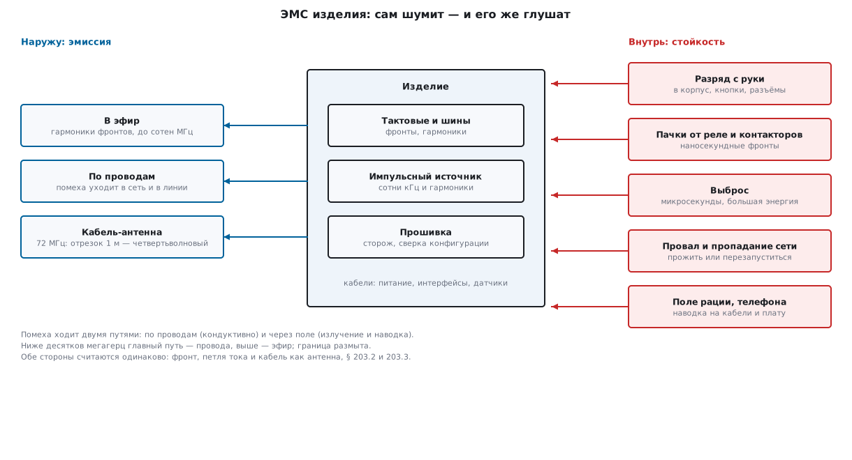
A threat map for a particular instrument takes an evening: list all the cables (power, interfaces, sensors), everything a person touches (enclosure, buttons, connectors), everything that arcs and switches nearby (relays, contactors, motors), and all your own noise sources (clocks, buses, the switcher). Further on in this section you will see that almost every "source → victim" pair is closed off by one of the standard measures.
203.2 What radiates in an instrument: edges, clocks, cables
What radiates is not "the 72 MHz frequency" but the edges. A square wave consists of odd
harmonics: 72, 216, 360 MHz and up; their amplitude falls off slowly
until the frequency reaches the envelope corner 1/(π·t_edge) — for a
1 ns edge that is 318 MHz, for 5 ns it is 64 MHz. Above the corner the spectrum drops fast,
so the slower the edge, the shorter the tail of harmonics. The Fourier series of a
3.3 V trapezoid at 72 MHz (spectrum.py, the DFT agrees with the analytical
formula to better than 2 %):
| Harmonic | Frequency | 1 ns edge | 5 ns edge | Drop |
|---|---|---|---|---|
| 1 | 72 MHz | 2.083 V | 1.681 V | 1.9 dB |
| 3 | 216 MHz | 0.648 V | 0.051 V | 22.0 dB |
| 5 | 360 MHz | 0.336 V | 0.044 V | 17.7 dB |
| 9 | 648 MHz | 0.102 V | 0.016 V | 16.3 dB |
The first harmonic — the signal itself — hardly changed, while the tail fell
by an order of magnitude. Hence the rule: pin speed should be the minimum
sufficient. On F1 it is set in the pin configuration — 2, 10 or
50 MHz (the GPIO_Speed_… enumeration in the pack header); on F4 and later families
by the OSPEEDR register. "50 MHz" on a pin that toggles an LED
is a free transmitter.
A centimetre-long trace on the board radiates weakly by itself — the trouble is
the cables: a wire a quarter wavelength long is already a tuned antenna.
The wavelength is λ = c/f:
| Frequency | λ | λ/4 |
|---|---|---|
| 72 MHz | 4.16 m | 1.04 m |
| 216 MHz | 1.39 m | 34.7 cm |
| 360 MHz | 0.83 m | 20.8 cm |
A one-metre power cable is a quarter-wave antenna right at the clock frequency, and a thirty-centimetre lead to a sensor is almost an antenna for the fifth harmonic. What drives the antenna is common-mode current — the current that flows along all conductors of the cable in the same direction and returns through capacitance to the surroundings: an estimate with the short-dipole formula gives, from 5 µA of common-mode current on a 30 cm cable at 216 MHz, a field of about 68 µV/m at three metres — the order of what is allowed for a residential environment. Microamps! That is why a common-mode choke or a ferrite bead on the cable (section 168) does more for emission than any change to the circuit.
The third source is the switching converter (section 58): hundreds of kilohertz of switching and harmonics up to tens of megahertz. It is fixed on the board: minimum area of the hot loop and a solid ground under it (sections 130, 181), and for high-speed nets and return currents see section 132г.
⚠️ You cannot hide the frequency, but you can hide the edge. You cannot move the clock down — the work needs it. But edges are almost always faster than the circuit requires: on GPIO, on SPI, and on the gate of the switcher's transistor (there the edge is set by the gate resistor). Slowing the edges is the first and cheapest measure.
203.3 Immunity: discharge, bursts, surge, dip
Immunity tests look different, but each one imitates a specific event in the product's life.
Electrostatic discharge. A person in a dry room is a charged capacitor:
the test generator model is 150 pF charged to a few to tens of
kilovolts and discharged through 330 Ω (a hand holding a metal object).
The ngspice model esd.cir at 8 kV: peak current 24.2 A, decay to 1/e
in 49.5 ns, 4.8 mJ dissipated in the resistor — the integral agrees
with the formula E = CU²/2 = 0.5 · 150 pF · (8 kV)² = 4.8 mJ
(F·V² = C·V = J — the units check out). Peak power is
U²/R ≈ 194 kW: millijoules, but in nanoseconds. That is 24 times more
energy than in the human body model from the IC datasheet —
why the built-in protection is not enough is covered in 62.8. The discharge hits
everything a person touches: enclosure, buttons, connectors — and a contact
discharge is nastier than an air discharge: it has a specified nanosecond
edge with a spectrum reaching gigahertz.
Bursts. Every contactor and relay in a cabinet, when it breaks an inductive
load, arcs with a series of nanosecond pulses. The coil of a small relay
(100 mH, 30 mA) stores only 45 µJ, but without a snubber the break
rings the coil's circuit up to U = I·√(L/C) ≈ 2.1 kV — and the arc
repeats while the contacts separate. The energy of each pulse
is negligible; what is dangerous is the edge: the coupling.cir model applies a
300 V edge in 5 ns to a "foreign" wire lying in the same harness as ours
(10 pF of capacitance between them):
| Where it arrived through 10 pF | Peak on the line |
|---|---|
| high-impedance input, 10 kΩ pull-up | 293 V |
| line with a 100 Ω load | 60 V |
| 100 Ω plus a 1 nF capacitor | 2.9 V |
| the same edge, but over 1 µs, into 100 Ω | 0.3 V |
Three conclusions from one table: a nanosecond edge gets through
picofarads (i = C·dU/dt = 10 pF · 60 V/ns = 0.6 A); high-impedance inputs
are defenceless, low-impedance ones are five times better, and a capacitor at the input reduces
the pickup a hundredfold; to a slow surge the same 10 pF make no difference.
Surge. A pulse of microseconds to milliseconds from switching heavy loads and from lightning-induced pickup: the voltage is lower than for static, but the energy is no longer milli- but joules. It is met not by an MCU pin but by the board input: a clamp, a fuse and their correct order — section 173.
Dips and interruptions. The mains "blinks" for half a cycle to a cycle: the instrument must either ride through it on stored energy or restart cleanly — but not hang and not corrupt the data in Flash. Which of these you choose is a decision that must be made and written down before the tests, not after.
203.4 The first line of defence: power input, interfaces, enclosure
The general principle: meet the interference at the boundary, while it has one way in, not ten.
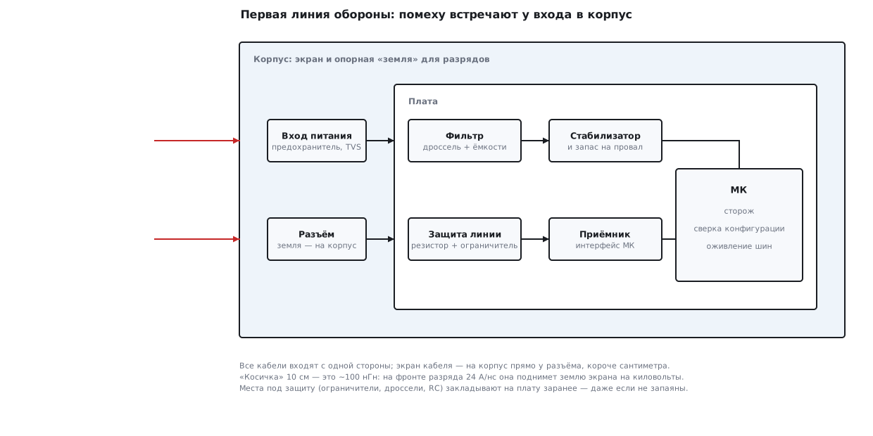
The power input is the chain from section 173: fuse, reverse-polarity protection, clamp, followed by a filter and a regulator. A mains dip is held by a storage capacitor: 1000 µF discharged by a 1 W load from 12 to 8 V gives 40 ms — a mains cycle with margin. Longer than that is no longer a job for the capacitor but a deliberate "we will restart": the PVD brown-out detector (section 10.7) warns the firmware in time so that it can finish the log and not start writing to Flash.
Interfaces. Everything that leaves the board gets a series resistor and a clamp at the connector (sections 62.3, 62.9); long and inter-unit lines get RS-485 with its own protection (section 89.4); the harshest environment gets galvanic isolation (section 54). Against common-mode interference and for emission — a common-mode choke or a bead on the cable (section 168). A capacitor of a few nanofarads at the input is exactly that "2.9 V instead of 293 V" row from the table above.
Enclosure and ground. A metal enclosure is a shield and a discharge receiver: static goes into it, bypassing the circuit — if the board ground is connected to the enclosure at the connectors and the discharge path does not cross the board. The rules that give most of the result:
- all cables enter on one side of the enclosure — otherwise interference that entered on the left will exit on the right straight through the board;
- the cable shield is bonded to the enclosure all around its circumference or with a lead shorter than
a centimetre. A 10 cm pigtail is about 100 nH; on a discharge edge of
24 A/ns it lifts the shield ground by
U = L·di/dt≈ 2.4 kV — the shield turns into an interference injector; - a slot in a shield is an antenna: it is transparent to waves whose λ/2 is comparable to its length (a 15 cm slot is "tuned" to 1 GHz — right in the discharge spectrum); covers and seams are bonded more often, rows of vias stitch the copper pours (section 132г.7);
- the ground is solid, return currents run under their own signals (sections 130, 181).
🔧 Build the defence in from the start. Footprints for clamps, beads and RC at every connector are laid out on the board from the first revision — unpopulated, they cost nothing. If the lab finds a problem, the rework is a soldering iron and an hour, not a new board and a month.
203.5 Firmware that survives interference
The electronics absorbs the energy, but some interference reaches the die — and then the firmware saves the product. Its defence has three tiers.
The watchdog (section 12) is the last line: the independent IWDG restarts a program that has hung for good. But a reset is an admission of defeat for tens of milliseconds: for a counter it means lost pulses, for a controller a jolt. That is why a second tier sits above the watchdog.
Checking the peripheral configuration. Interference can flip a bit in a configuration register: the program is intact, the loop is running, the watchdog is fed — and the UART is silent because its divider was reset. Configuration registers are protected by nothing except the firmware — so after full initialization a reference copy is taken, and the main loop checks against it:
enum { NCFG = 8 };
volatile uint32_t *cfg_addr[NCFG];         /* что охраняем: заполняется при инициализации */
static uint32_t cfg_good[NCFG];            /* эталон после инициализации */
static uint32_t cfg_ref;                   /* его контрольная сумма */
void cfg_snapshot(void)                    /* вызвать после полной инициализации */
{
    for (int i = 0; i < NCFG; i++)
        cfg_good[i] = *cfg_addr[i];
    cfg_ref = cfg_crc();
}

int cfg_guard(void)                        /* из главного цикла, раз в десятки мс */
{
    if (cfg_crc() == cfg_ref)
        return 0;                          /* всё на месте — дёшево: одна сумма */
    int fixed = 0;
    for (int i = 0; i < NCFG; i++)
        if (*cfg_addr[i] != cfg_good[i]) {
            *cfg_addr[i] = cfg_good[i];    /* вернуть как было */
            fixed++;
        }
    return fixed;                          /* и записать событие в журнал */
}
cfg_addr[] holds the addresses of configuration registers — GPIOA->CRL,
USART1->CR1 — configuration only, not data and not flags. A run of
_verify/emc203/emc_guard.c on a PC: a single flipped bit was detected
and restored in one call, flips in two registers gave "registers
restored: 2", and the checksum after the repair matched. For Cortex-M3
the whole mechanism built into 172 bytes of code and 68 bytes of RAM.
Restoring what is outside. A discharge in the middle of an I²C transaction leaves the slave holding SDA low — the bus is revived with manually generated clocks (recipe 17.6). A UART receiver is resynchronized after interference on a framing error. A crystal choked by interference is caught by the clock security system: it switches the MCU to the internal oscillator (section 6). Inputs are read three times and the majority value is taken, and the state of critical outputs is rewritten periodically — just like the configuration.
⚠️ Every reset goes into the log. The reset cause flags (section 12.4)
and the cfg_guard trigger counter in non-volatile memory
or telemetry (section 190) are the only way to find out that an instrument
at the customer's site catches interference once an hour. An instrument that "just blinks
sometimes" is an instrument that silently restarts.
203.6 Testing in the workshop: a lighter, a relay, a receiver
Before the lab, gross holes can be found with improvised tools — as long as you honestly understand what they show and what they do not.
A piezo lighter as a discharge generator. A piezo element without the burner gives a 3–4 mm spark; air breaks down at roughly 3 kV/mm, so this is a pulse of the order of 9 kV — the level of a serious test. Click it at the enclosure, near the buttons, into the connectors, along the gaps; meanwhile the instrument is running, and a person next to it watches its behaviour.
🔧 How to zap. First an indirect discharge: a spark into a metal plate standing a couple of centimetres from the product; then into the enclosure and the metal of the connectors; last of all next to the plastic buttons and seams. Never discharge into an open board without an enclosure: a live die does not always survive that, and the product is tested assembled — the way a person with a charged hand will meet it.
A relay as a burst generator. A relay that switches its own coil through its own normally closed contact is a classic buzzer: the contacts arc continuously, and without a snubber every break rings at kilovolts (the calculation from 203.3: about 2.1 kV). A couple of turns of wire from this "rig" around the product's harness — and you see whether the interfaces survive nanosecond edges. A mains dip is the easiest to imitate: pull the plug and push it back, release the power supply button for half a second — and watch whether the instrument restarted cleanly.
A receiver as an emission indicator. A medium-wave AM receiver, a cheap walkie-talkie or an SDR dongle next to the board hears the "singing" of the switcher and the clocks. You cannot measure an absolute level this way, but a "before/after" comparison works very well: slowed the edges, put on a bead, closed the lid — did the hiss in the receiver drop or not.
| Rig | What it imitates | What it will NOT show |
|---|---|---|
| piezo lighter | electrostatic discharge ~9 kV | specified current and edge; "how many kV we withstand" |
| relay buzzer at the harness | bursts from contactors | the coupling level to real wiring |
| pulling the plug | mains dip and interruption | the shape and phase of a specified dip |
| receiver near the board | near-field emission | absolute level, far field, the whole frequency range |
⚠️ A home rig finds holes in the defence; it does not confirm margin. None of these experiments is standardized: the energy of a lighter is not the energy of a test gun, the coupling of the relay to the harness is arbitrary. "Everything passed at home" means "there are no gross holes", and nothing more.
203.7 When to go to the lab and what to take with you
You go to the lab when the product is sold or built into other people's systems: the list of formal tests depends on the market and the product class, and the home check from 203.6 saves paid hours — it is expensive to look on a standard test bench for something a lighter would have found.
A kit packed for the trip marks a prepared team:
- two or three units of the product with the standard cables at standard length and all covers: a different cable is a different antenna, and the result will not repeat;
- test firmware: an "alive / restarted / recovered by itself" indicator, a log of resets and configuration-check triggers — otherwise nobody will notice a brief glitch on the test bench;
- written criteria: what counts as normal for each kind of disturbance. There are three outcomes — did not notice; glitched and recovered by itself; needs a person. Which outcome is acceptable for which disturbance is a decision made by the developer before the tests;
- a soldering iron and a box of fixes: beads, clamps, capacitors, jumpers — for the footprints provided in 203.4; half a day at the bench with a soldering iron replaces a month of correspondence;
- time for a retest: after any change to the board the tests are repeated — this goes into the plan and the budget instead of coming as a surprise.
203.8 Pitfalls
Everything passes on the desk, fails at the customer's. The cable is part of the antenna: a lead of different length and routing changes both emission and immunity; λ/4 for the fifth harmonic of 72 MHz is only 21 cm. Test with the standard cables, routed as in real use.
The watchdog restarts, but the instrument is still "dead". Interference flipped a configuration register: the loop is running, the watchdog is fed, the peripheral is silent. You need configuration checking and restoring (203.5), not just the IWDG.
There is a shield, but it does nothing. The cable shield is soldered with a 10 cm "pigtail": that is ~100 nH, and a discharge edge lifts the shield ground by ~2.4 kV. The shield goes to the enclosure right at the entry, short or all around.
A discharge into a plastic button brings the instrument down. The breakdown goes not through the plastic but along the gap around the button to the traces behind it: at ~3 kV/mm eight kilovolts are enough for almost 3 mm of air. Route traces and contacts away from gaps, and close the gaps.
Slowed the edges — the interface can no longer keep up. Pin speed is the minimum sufficient, not the minimum: the edge is part of the signal's timing budget, and on fast buses it is tight (section 132г).
"Isolated" the ground with a cut — and got more interference. The return current went around the cut in a large loop, and the loop became an antenna (section 181). A solid ground is almost always better than artistic cuts.
The switcher is noisy only under load. At no load the converter skips pulses and the currents are small; listen with the receiver and measure emission under the working load.
203.9 Summary
- EMC has two sides: emission (do not disturb) and immunity (do not fail); the paths are wires and field, below tens of MHz the main path is the wires.
- Edges radiate: stretching the edge of a 72 MHz square wave from 1 to 5 ns drops
the third harmonic by 22 dB, the fifth by 17.7 dB, the signal by 1.9 dB;
the envelope corner
1/(π·t_edge)is 318 MHz at 1 ns, 64 MHz at 5 ns. - Cables are antennas: λ/4 is 1.04 m at 72 MHz, 34.7 cm at 216 MHz, 20.8 cm at 360 MHz; common-mode microamps are enough for a reject — a choke and a bead on the cable.
- An 8 kV discharge from 150 pF through 330 Ω: 24.2 A, 49.5 ns, 4.8 mJ, peak power ~194 kW; a 300 V/5 ns edge through 10 pF gives 293 V on a high-impedance input, 60 V on 100 Ω, 2.9 V with a 1 nF capacitor.
- Defence at the boundary: the power input chain (173), a resistor and a clamp at the connectors (62), a shield without pigtails (10 cm = 2.4 kV on a discharge edge), cables on one side; 1000 µF holds a 40 ms dip at 1 W.
- Firmware: watchdog + configuration check (172 bytes of code, 68 bytes of RAM on Cortex-M3) + bus recovery (17.6) + reset log.
- The workshop finds holes (lighter ~9 kV, relay buzzer ~2.1 kV, receiver "before/after") but does not confirm margin — margin is confirmed by the lab, which you visit with cables, criteria and a soldering iron.
Full source code
emc_guard.c — checking the peripheral configuration after interference.
/* Раздел 203.5: сверка конфигурации периферии после помехи.
 *
 * На плате в cfg_addr[] кладут адреса регистров конфигурации:
 * &GPIOA->CRL, &USART1->CR1, &TIM2->CR1, ... — только конфигурацию,
 * не данные и не флаги. Здесь, на компьютере, вместо периферии —
 * массив fake_regs, а «помеха» перещёлкивает в нём один бит.
 *
 * Сборка на ПК:  gcc -O2 -Wall -Wextra -o emc_guard emc_guard.c && ./emc_guard
 * Для кристалла: arm-none-eabi-gcc -mcpu=cortex-m3 -mthumb -O2 -DNO_HOST_TEST -c emc_guard.c
 */
#include <stdint.h>
#ifndef NO_HOST_TEST
#include <stdio.h>
#endif

enum { NCFG = 8 };
volatile uint32_t *cfg_addr[NCFG];         /* что охраняем: заполняется при инициализации */
static uint32_t cfg_good[NCFG];            /* эталон после инициализации */
static uint32_t cfg_ref;                   /* его контрольная сумма */

static uint32_t cfg_crc(void)
{
    uint32_t crc = 0xFFFFFFFFu;
    for (int i = 0; i < NCFG; i++) {
        crc ^= *cfg_addr[i];
        for (int b = 0; b < 32; b++)
            crc = (crc >> 1) ^ (0xEDB88320u & (0u - (crc & 1u)));
    }
    return crc;
}

void cfg_snapshot(void)                    /* вызвать после полной инициализации */
{
    for (int i = 0; i < NCFG; i++)
        cfg_good[i] = *cfg_addr[i];
    cfg_ref = cfg_crc();
}

int cfg_guard(void)                        /* из главного цикла, раз в десятки мс */
{
    if (cfg_crc() == cfg_ref)
        return 0;                          /* всё на месте — дёшево: одна сумма */
    int fixed = 0;
    for (int i = 0; i < NCFG; i++)
        if (*cfg_addr[i] != cfg_good[i]) {
            *cfg_addr[i] = cfg_good[i];    /* вернуть как было */
            fixed++;
        }
    return fixed;                          /* и записать событие в журнал */
}

#ifndef NO_HOST_TEST
static volatile uint32_t fake_regs[NCFG];  /* «периферия» для опыта на ПК */

int main(void)
{
    for (int i = 0; i < NCFG; i++) {       /* «инициализация периферии» */
        fake_regs[i] = 0xB4430000u + 0x111u * (uint32_t)i;
        cfg_addr[i] = &fake_regs[i];
    }
    cfg_snapshot();
    printf("эталон: %d регистров, CRC 0x%08X\n", NCFG, cfg_ref);
    printf("тихий проход: guard=%d (расхождений нет)\n", cfg_guard());

    fake_regs[3] ^= 1u << 13;              /* «помеха» перещёлкнула бит */
    printf("помеха: бит 13 регистра 3 перещёлкнут, CRC 0x%08X\n", cfg_crc());
    printf("guard: восстановлено регистров: %d\n", cfg_guard());
    printf("после восстановления: CRC %s\n",
           cfg_crc() == cfg_ref ? "совпал" : "НЕ совпал");

    fake_regs[1] ^= 1u << 0;               /* и два регистра сразу */
    fake_regs[6] ^= 1u << 31;
    int fixed = cfg_guard();
    printf("помеха в двух регистрах: guard=%d, CRC %s\n",
           fixed, cfg_crc() == cfg_ref ? "совпал" : "НЕ совпал");
    return 0;
}
#endif
Next: section 204 "Reliability: margins, aging and in-house testing" — the instrument survived the interference; now make it live for years.