 Embedded HandbookApps
202. Calibration on the production line
On a prototype you trim a measurement channel with a constant in the code: tweak it, it matches, forget about it. In series production that does not work: every unit has its own divider, its own reference and its own offset, while the firmware is the same for all of them. The difference between "works on my bench" and "works on every hundredth board" is a procedure on the line: apply a reference value, compute the corrections for this particular unit, write them into it and verify them. This section covers how much error builds up from tolerances, what the factory has already calibrated inside the chip, how to calibrate the rest and where to store the coefficients.
All numbers come from the calculation in _verify/lcal202/budget.py and from a run of the model
_verify/lcal202/lcal.c (gcc 12 in the stm-lab:1 image); addresses come from the headers
and documentation of the F1 and F4 packs.
Terms used in the documentation
Term Meaning end-of-line calibration calibration at the end of the line, at release device under test (DUT) the unit being tested test accuracy ratio (TAR) how much more accurate the reference is than the tolerance golden unit a reference unit used to check the station itself guard band acceptance tolerance set tighter than the product tolerance as-found / as-left readings "as received" and "as left" calibration interval time between calibrations piecewise linear approximation by straight segments between points
202.1 Why calibrate every unit
Let us build the error budget of a typical channel: measuring up to 24 V through a 68 kΩ / 10 kΩ divider with ±1 % resistors, the ADC reference is the 3.3 V supply from a ±1 % regulator, a 12-bit ADC. The division ratio is 0.128205, the full scale is 25.74 V.
The divider error is found by going through the tolerance corners: both resistors at the edges of ±1 % in every combination. The worst pairs are R1 low with R2 high and the other way round:
| Term | Worst case |
|---|---|
| 68 kΩ / 10 kΩ divider, ±1 % resistors | −1.73 % … +1.76 % |
| reference: supply from a ±1 % regulator | ±1.00 % |
| F1 ADC, total unadjusted error ±5 LSB | ±0.12 % |
| sum | ±2.88 % — that is ±0.69 V at a 24 V input |
| root sum of squares | ±2.03 % — ±0.49 V |
For a quick estimate one formula is enough: the relative shift of the division ratio ≈ (1 − k)·(δR2 − δR1). At k = 0.128 it gives 1.74 % — almost exact; for a symmetric 10 kΩ / 10 kΩ divider the shift is smaller, exactly ±1.00 %.
The worst case is rare, but the middle of the distribution is no comfort either: a Monte Carlo run over 100000 "units" with uniform tolerances gives a median error of 0.68 % of full scale, and 32 % of the batch is worse than 1 % — every third instrument. For comparison: 1 LSB of a 12-bit ADC is 0.0244 % of full scale. The worst case is 118 times larger: the channel's resolution is eaten not by noise and not by the ADC, but by component tolerances.
Sensors are worse still. For the F103 internal temperature sensor the datasheet
voltage at 25 °C is anywhere from 1.34 to 1.52 V with a slope of 4.3 mV/°C: a spread of
±90 mV means an error of up to ±21 °C if you compute with the typical value.
VREFINT on F1 wanders from 1.16 to 1.26 V — from −3.3 % to +5.0 % of the typical
1.20 V. No carefully derived formula cures this: the numbers are different
for every unit.
The conclusion from the budget: the accuracy of a production instrument is set not by the circuit and not by the resolution, but by whether this particular unit was compared with a reference. Calibration moves the accuracy from the component tolerances to the accuracy of the reference — in a minute on the line.
⚠️ Calibration does not cure drift. The corrections are taken at one temperature on one day. A reference drift of 100 ppm/°C over 50 °C is already 0.5 %; ageing and temperature effects are separate lines of the budget. If they exceed the tolerance, you need temperature compensation, or more stable components, or periodic recalibration (a calibration interval).
202.2 Factory calibration inside the chip
The factory has already done part of the work: when the die is released, values measured
on test equipment more accurate than any home-made station are written
into system memory. Their addresses are the key constants of this section
(checked against the pack header stm32f4xx_ll_adc.h and the documentation of both
families):
| What is stored | F103 | F407 | Measurement conditions |
|---|---|---|---|
| unique device ID, 96 bits | 0x1FFF F7E8 |
0x1FFF 7A10 |
— |
VREFINT_CAL — VREFINT code |
none | 0x1FFF 7A2A |
30 °C, VREF+ = 3.3 V |
TS_CAL1 — temperature sensor code |
none | 0x1FFF 7A2C |
30 °C, VDDA = 3.3 V |
TS_CAL2 — temperature sensor code |
none | 0x1FFF 7A2E |
110 °C, VDDA = 3.3 V |
| OTP: 512 bytes for your own data | none | 0x1FFF 7800 |
written once |
| Flash size register | 0x1FFF F7E0 |
0x1FFF 7A22 |
— |
F1 has no factory ADC codes at all — the headers and the reference manual have
only typical values from the datasheet, which is why the F1 temperature sensor without
your own calibration is off by tens of degrees (202.1). On F4 the LL driver provides
ready names VREFINT_CAL_ADDR, TEMPSENSOR_CAL1_ADDR
and TEMPSENSOR_CAL2_ADDR; the header comments also give the spread of the measurement
conditions: temperature 30 ±5 °C, reference 3.3 V ±10 mV.
How to use these codes — formulas and integer conversion — is already
covered in 14.9: supply voltage from VREFINT_CAL, temperature from the two points
TS_CAL1/TS_CAL2. What matters here is something else: the factory codes describe only
the die itself. The reference measured by the factory is VREFINT; the sensor is the one
on the die. The divider, shunt, amplifier and external sensor were never seen by the factory —
their spread is removed only by your own calibration of the assembled product.
⚠️ Check the cell before use. Unprogrammed system memory reads as
0xFFFF. If you find0xFFFFinTS_CAL1, this die has no code, and you are left with the typical value from the datasheet. Also, the addresses differ between families: the table above is for F103 and F407; for another chip, look the address up in its datasheet instead of copying it from here.
202.3 Your own calibration: one point, two points, a curve
The lcal.c model builds a "unit" with a typical set of problems: a reference 1.2 %
above nominal, an offset of +6 LSB, noise of ±2 LSB. Converting with nominal values,
code × 3300 / 4095, gives an error of up to 35 mV on it.
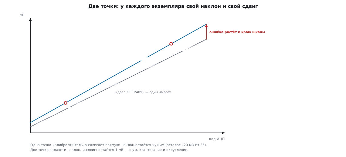
One point removes only the offset: apply a reference 1650 mV, compare it with the reading, store the difference. The correction came out at +15 mV, but at the ends of the scale 20 mV remained — the whole slope error (reference and divider error) is still there. One point is enough when the slope is set by accurate components and only the offset wanders: taring a scale (102), the zero of a current sensor.
Two points set both the offset and the slope — the line of this particular unit. The station applied 330 and 2970 mV — 10 and 90 % of full scale; the model averaged 64 samples per point and got codes 411 and 3647. Then come two coefficients:
/* по двум точкам: эталон дал v1 и v2 (мВ), устройство — коды c1 и c2 */
static void cal_two_point(int32_t v1, int32_t c1, int32_t v2, int32_t c2, cal_rec_t *r)
{
    r->gain_q16  = (int32_t)((((int64_t)(v2 - v1)) << 16) / (c2 - c1));
    r->offset_mv = v1 - (int32_t)(((int64_t)c1 * r->gain_q16 + 32768) >> 16);
}
For the model unit this gave gain_q16 = 53465 and an offset of −5 mV; the residual
error over the whole scale is 1 mV: noise, quantization and rounding. Two measurements
turned 35 mV into 1 mV.
A curve is needed when the physics is nonlinear and a straight line does not fit within the tolerance: an NTC thermistor (96.2), a thermocouple. Then calibration is not two coefficients but a table with piecewise linear approximation between nodes; you need enough points that the sag between neighbouring nodes is smaller than the tolerance. The order of choice is always the same: first estimate the residual after a straight line — if it is below the tolerance, no curve is needed; two points are cheaper both on the line and in the firmware.
🔧 How to choose. Offset wanders, slope is accurate — one point. The reference, divider or gain wander — two points at 10 and 90 % of full scale. The residual after the line is larger than the tolerance — a table of nodes. And in every case each point is the average of dozens of samples, not a single one (Pitfalls).
202.4 The reference on the line
Calibration transfers the instrument's accuracy onto the accuracy of the reference, so the reference must be noticeably more accurate than the product tolerance — otherwise its error is simply copied into the coefficients. The rule of thumb is a margin of at least 4 times, a comfortable one is 10 (test accuracy ratio): for a ±0.5 % tolerance the reference must be no worse than 0.05–0.125 %. A laboratory source with a meter of that class is an ordinary thing; what matters is that it too is verified on schedule, and an overdue verification of the reference makes the calibration of the whole batch after it untrustworthy.
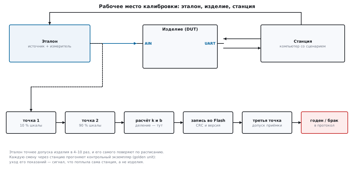
The station is a computer with a script: set a point on the reference, tell the product to measure, collect the codes, compute the coefficients, write them, verify. In the firmware, service commands over UART (16) are enough for this — the console of mini-projects 196–198 works the same way: "give me the raw channel code", "take the coefficients", "show what is stored". The same commands come in handy later in servicing.
🔧 Checking the station itself. Once per shift, a reference unit that never leaves the line (golden unit) is run through the station. Its readings are recorded before and after — as-found and as-left. If the golden unit drifts, the station or the reference has drifted, and everything calibrated since the previous golden-unit run is suspect. This is cheaper than hearing the same thing from the customer.
202.5 Where to write the coefficients
The coefficients belong to the unit just like its serial number, and they live not in the firmware but in the product itself. The record format is like the settings log in 11.8, but simpler: calibration is written once at release, wear levelling and page rotation are not needed, but a "record present and intact" marker is mandatory:
typedef struct {
    uint32_t magic;      /* 'L''C''A''L' — страница не пуста */
    uint16_t version;    /* раскладка структуры */
    uint16_t count;      /* сколько каналов откалибровано */
    uint32_t uid[3];     /* копия 96-битного номера кристалла */
    int32_t  gain_q16;   /* мВ на код, Q16: 65536 = 1,0 */
    int32_t  offset_mv;  /* сдвиг после умножения */
    uint32_t crc;        /* CRC-32 всего, кроме этого поля */
} cal_rec_t;
The record is 32 bytes; CRC-32 uses the same polynomial 0xEDB88320 as in 11.8,
and on F4 the hardware unit computes it (43.1). A run of the model shows all three
protection mechanisms at once:
запись: 32 байт, CRC-32 = 0xCBF8156D
испорчен один бит: CRC не сошлась — запись отвергнута
стёртая страница: magic 0xFFFFFFFF != 0x4C41434C и CRC не сошлась — калибровки нет
version=2 при ожидаемой 1: раскладка другая — запись не используется
The copy of the unique ID guards against a quiet failure: the firmware together with a "foreign"
calibration page was cloned onto another board, the CRC matches, but the numbers belong to
another unit. Comparing uid with 0x1FFF F7E8 (F1) or 0x1FFF 7A10
(F4) catches this at startup.
Where to put it:
- A separate Flash page (erase and write — 11.5), not the one holding the settings log: "factory reset" erases the settings but must never touch the calibration. The page is excluded from the firmware image in the linker script (11.3).
- On F4 — the OTP area: 512 bytes from address
0x1FFF 7800, 16 blocks of 32 bytes, each locked forever by its own byte. It is written once, never erased, and a full Flash erase does not touch it — according to the reference manual, Mass Erase does not affect the OTP area. Our 32-byte record fits exactly into one block.
⚠️ No calibration is a state, not a failure. A fresh board before the station shows
magic 0xFFFFFFFF. The firmware must work in this state too: compute with nominal values, honestly report "not calibrated" in the service command and not present its measurements as accurate.
202.6 Verification after calibration
The coefficients are written, but the instrument is not yet good. What makes it good is a check at a point that did not take part in the calibration: in the model it is 1650 mV, the middle of the scale between the points 330 and 2970:
контрольная точка 1650 мВ: прибор показал 1650 мВ, ошибка +0 мВ (допуск ±5)
The acceptance tolerance is set tighter than the product tolerance — with a guard band for the reference error and the measurement noise (guard band). The product promises ±10 mV, the reference and the station contribute ±2 mV — accept at ±8 mV: then a unit that passed acceptance is guaranteed to be within tolerance even if the reference this time erred to its worst side.
Failed — one recalibration, no more. A unit that passes on the second or third try has not "finally come out right" — it is unstable or faulty, and tomorrow it will drift again. From here on it is not trimming but analysis: almost always a "calibration reject" hides not spread but a defect — a wrong value in the divider, a bad solder joint, a swapped channel. On the as-found distribution across the batch this is visible at once: the spread forms a bell curve, defects stick out as outliers.
🔧 A record for every unit. The station writes a file per serial number: date, as-found, point codes, coefficients, as-left, verdict. A batch of such records is free statistics: the median creeps from batch to batch — the component supply has changed; the tail of outliers grows — look for an assembly defect before it reaches the customer.
202.7 Conversion in the firmware
The station could compute the line however it liked, but the instrument has to live with it in every measurement. The right division of labour: all division is done once at the station (or once when the coefficients are received); in the working loop there is only a multiplication and a shift:
/* в приборе: только умножение и сдвиг, деление осталось на станции */
static int32_t cal_apply(uint16_t code, const cal_rec_t *r)
{
    return (int32_t)(((int64_t)code * r->gain_q16 + 32768) >> 16) + r->offset_mv;
}
The multiplier is in Q16 format (69.9): 65536 means 1.0, our 53465 is
0.8158 mV per code. The term 32768 is half the shift divisor: rounding
to nearest rather than truncation (64.8). The product 4095 × 65536
fits even in 32 bits, but int64_t settles the question for any multiplier —
on Cortex-M3 and M4 this is a single 32×32→64 multiply instruction.
Floating point is not needed here: F1 has no hardware FPU at all (69.6),
and float with its seven digits (69.2) will not add accuracy to a line made of two
integer coefficients. The model ran both variants over all 4096
codes:
целые против double по всем 4096 кодам: расхождение не больше 1 мВ
The discrepancy is 1 mV, and it is rounding at the boundaries, not a systematic error. The integer path is also reproducible bit for bit on any compiler — for calibration that is a separate advantage: the station can compute in advance what the instrument must show and compare it exactly.
202.8 Pitfalls
Calibrated, reflashed — the instrument is wrong again. The update was flashed with a full erase, and the coefficient page went away together with the old firmware. Exclude the calibration page from the image and erase only by address; on F4 OTP is the most reliable — Mass Erase does not touch it.
Two points taken, but the end of the scale is still off. The points were taken close together and with a single sample each: in the model, points at 300 and 600 mV taken once each gave up to 17 mV at the end of the scale — the noise of the points stretched over the whole length of the line. Points go at 10 and 90 % of full scale, each the average of 64 samples: residual 1 mV.
Good on the line, wrong at the customer's in the frost. The calibration was taken at room temperature and does not cure drift: the reference alone at 100 ppm/°C over a 50 °C swing moves by 0.5 %. Either more stable components, or temperature compensation using a second measured quantity, or an honest tolerance.
Every tenth unit is a "calibration reject". That is not spread: the spread is already counted in the budget and built into the tolerance. Outliers in the as-found distribution are defects: a wrong value, a bad joint, an open circuit. They are not recalibrated, they are repaired.
Factory codes read — the temperature is absurd. Either the address
is from another family (F103 has no codes at all, F407 has 0x1FFF 7A2A…2E),
or the cell is empty and reads 0xFFFF, or the reference in the instrument is not the 3.3 V
at which the factory took the codes — then first correct for the reference as in 14.9.
The CRC matches, but the readings belong to someone else. The calibration page was cloned
together with the firmware onto another board. The record must carry a copy of the unique
device ID (0x1FFF F7E8 on F1, 0x1FFF 7A10 on F4), and the firmware
compares it at startup.
202.9 Summary
- Component tolerances eat accuracy down to the resolution: a ±1 % divider and a ±1 % reference give up to ±2.88 % of full scale — 118 times more than 1 LSB of a 12-bit ADC; in the Monte Carlo batch every third unit was worse than 1 %.
- The factory calibrates only the die: the F407 system memory holds
VREFINT_CAL(0x1FFF 7A2A),TS_CAL1/TS_CAL2(0x1FFF 7A2C/2E, 30 and 110 °C at 3.3 V); F103 has no factory ADC codes — only the unique ID0x1FFF F7E8. - One point removes the offset (in the model 35 → 20 mV), two points remove offset and slope (→ 1 mV); points at 10 and 90 % of full scale, each the average of 64.
- The reference is 4–10 times more accurate than the product tolerance, with a valid verification; the station is checked every shift with an unchanging unit.
- Acceptance is at a third point with a guard band: the product tolerance minus the station error; one recalibration, then defect analysis.
- Coefficients go in their own Flash page: magic, version, UID copy, CRC-32,
32 bytes; F4 has a 512-byte OTP from
0x1FFF 7800that is not touched even by a full erase. - The working loop has only a multiplication and a shift: a Q16 multiplier, rounding
via +32768; the discrepancy with
doubleis no more than 1 mV over all 4096 codes.
Full source code
lcal.c — a model of calibrating a unit on the line.
/* Раздел 202: модель калибровки экземпляра на линии.
 *
 * gcc -std=c11 -Wall -Wextra -O2 lcal.c -o lcal && ./lcal
 *
 * «Изделие» — канал 0…3300 мВ с 12-битным АЦП, у которого опора на +1,2 %
 * выше номинала, смещение +6 LSB и шум ±2 LSB. «Эталон» подаёт точное
 * напряжение. Сравниваются: пересчёт без калибровки, одна точка, две точки;
 * целочисленный пересчёт против плавающей точки; запись коэффициентов
 * с CRC-32, версией и копией уникального номера кристалла. */
#include <stddef.h>
#include <stdint.h>
#include <stdio.h>
#include <stdlib.h>
#include <string.h>

/* ── модель экземпляра ────────────────────────────────────────────── */
#define VREF_REAL_MV  3340.0     /* опора на +1,2 % выше 3300 */
#define OFF_LSB       6          /* смещение канала, LSB */
#define NOISE_LSB     2          /* шум ±2 LSB */

static uint32_t lcg = 12345u;
static int32_t noise(void)                       /* равномерный ±NOISE_LSB */
{
    lcg = lcg * 1664525u + 1013904223u;
    return (int32_t)(lcg >> 16) % (2 * NOISE_LSB + 1) - NOISE_LSB;
}

static int32_t adc_code(double v_mv, int with_noise)
{
    int32_t c = (int32_t)(v_mv / VREF_REAL_MV * 4095.0 + 0.5) + OFF_LSB;
    if (with_noise)
        c += noise();
    if (c < 0) c = 0;
    if (c > 4095) c = 4095;
    return c;
}

/* среднее из 64 замеров — так станция снимает точку калибровки */
static int32_t adc_avg64(double v_mv)
{
    int32_t s = 0;
    for (int i = 0; i < 64; i++)
        s += adc_code(v_mv, 1);
    return (s + 32) / 64;
}

/* ── коэффициенты и их применение (то, что попадает в прошивку) ───── */
typedef struct {
    uint32_t magic;      /* 'L''C''A''L' — страница не пуста */
    uint16_t version;    /* раскладка структуры */
    uint16_t count;      /* сколько каналов откалибровано */
    uint32_t uid[3];     /* копия 96-битного номера кристалла */
    int32_t  gain_q16;   /* мВ на код, Q16: 65536 = 1,0 */
    int32_t  offset_mv;  /* сдвиг после умножения */
    uint32_t crc;        /* CRC-32 всего, кроме этого поля */
} cal_rec_t;

/* по двум точкам: эталон дал v1 и v2 (мВ), устройство — коды c1 и c2 */
static void cal_two_point(int32_t v1, int32_t c1, int32_t v2, int32_t c2, cal_rec_t *r)
{
    r->gain_q16  = (int32_t)((((int64_t)(v2 - v1)) << 16) / (c2 - c1));
    r->offset_mv = v1 - (int32_t)(((int64_t)c1 * r->gain_q16 + 32768) >> 16);
}

/* в приборе: только умножение и сдвиг, деление осталось на станции */
static int32_t cal_apply(uint16_t code, const cal_rec_t *r)
{
    return (int32_t)(((int64_t)code * r->gain_q16 + 32768) >> 16) + r->offset_mv;
}

/* наивный пересчёт «по номиналам» и одна точка (только сдвиг) */
static int32_t mv_naive(uint16_t code)
{
    return (int32_t)(((uint32_t)code * 3300u + 2047u) / 4095u);
}

/* ── CRC-32, тот же многочлен 0xEDB88320, что в 11.8 и 43.1 ───────── */
static uint32_t crc32_buf(const void *p, size_t n)
{
    const uint8_t *b = p;
    uint32_t crc = 0xFFFFFFFFu;
    while (n--) {
        crc ^= *b++;
        for (int i = 0; i < 8; i++)
            crc = (crc >> 1) ^ (0xEDB88320u & (0u - (crc & 1u)));
    }
    return ~crc;
}

static double max_err(int32_t (*conv)(uint16_t, const cal_rec_t *), const cal_rec_t *r)
{
    double worst = 0;
    for (int v = 0; v <= 3300; v++) {
        int32_t mv = conv((uint16_t)adc_code(v, 0), r);
        double e = mv > v ? mv - v : v - mv;
        if (e > worst)
            worst = e;
    }
    return worst;
}

static int32_t conv_naive(uint16_t c, const cal_rec_t *r) { (void)r; return mv_naive(c); }
static int32_t one_off;
static int32_t conv_one(uint16_t c, const cal_rec_t *r) { (void)r; return mv_naive(c) + one_off; }

int main(void)
{
    cal_rec_t rec = { 0x4C41434Cu, 1, 1, {0x11223344u, 0x55667788u, 0x99AABBCCu}, 0, 0, 0 };

    /* без калибровки */
    printf("без калибровки: наибольшая ошибка %.0f мВ\n", max_err(conv_naive, &rec));

    /* одна точка: эталон 1650 мВ, убрали только сдвиг */
    one_off = 1650 - mv_naive((uint16_t)adc_avg64(1650.0));
    printf("одна точка (1650 мВ): поправка %+d мВ, осталось %.0f мВ\n",
           one_off, max_err(conv_one, &rec));

    /* две точки на 10 %% и 90 %% шкалы, каждая — среднее из 64 замеров */
    int32_t v1 = 330, v2 = 2970;
    int32_t c1 = adc_avg64(v1), c2 = adc_avg64(v2);
    cal_two_point(v1, c1, v2, c2, &rec);
    printf("две точки (%d/%d мВ): коды %d/%d, gain_q16=%d offset=%d, осталось %.0f мВ\n",
           v1, v2, c1, c2, rec.gain_q16, rec.offset_mv, max_err(cal_apply, &rec));

    /* целые против плавающей точки: та же прямая на double */
    double gf = (double)(v2 - v1) / (c2 - c1), bf = v1 - c1 * gf;
    int32_t dmax = 0;
    for (int c = 0; c <= 4095; c++) {
        int32_t mi = cal_apply((uint16_t)c, &rec);
        int32_t mf = (int32_t)(gf * c + bf + (gf * c + bf >= 0 ? 0.5 : -0.5));
        int32_t d = abs(mi - mf);
        if (d > dmax)
            dmax = d;
    }
    printf("целые против double по всем 4096 кодам: расхождение не больше %d мВ\n", dmax);

    /* плохая калибровка: точки рядом (300 и 600 мВ) и по одному замеру */
    cal_rec_t bad;
    lcg = 7u;
    cal_two_point(300, adc_code(300.0, 1), 600, adc_code(600.0, 1), &bad);
    printf("точки рядом (300/600 мВ), по одному замеру: на шкале до %.0f мВ\n",
           max_err(cal_apply, &bad));

    /* приёмка в третьей точке */
    int32_t chk = cal_apply((uint16_t)adc_avg64(1650.0), &rec);
    printf("контрольная точка 1650 мВ: прибор показал %d мВ, ошибка %+d мВ (допуск ±5)\n",
           chk, chk - 1650);

    /* запись: размер, CRC, порча, стёртая страница */
    rec.crc = crc32_buf(&rec, offsetof(cal_rec_t, crc));
    printf("запись: %u байт, CRC-32 = 0x%08X\n", (unsigned)sizeof rec, rec.crc);

    cal_rec_t bit = rec;
    ((uint8_t *)&bit)[21] ^= 0x02;               /* один бит в gain_q16 */
    printf("испорчен один бит: CRC %s\n",
           crc32_buf(&bit, offsetof(cal_rec_t, crc)) == bit.crc ? "сошлась (ПЛОХО)" : "не сошлась — запись отвергнута");

    cal_rec_t blank;
    memset(&blank, 0xFF, sizeof blank);          /* стёртая Flash — все единицы */
    printf("стёртая страница: magic 0x%08X != 0x%08X и CRC не сошлась — калибровки нет\n",
           blank.magic, rec.magic);

    cal_rec_t old = rec;
    old.version = 2;
    old.crc = crc32_buf(&old, offsetof(cal_rec_t, crc));
    printf("version=%u при ожидаемой %u: раскладка другая — запись не используется\n",
           old.version, rec.version);
    return 0;
}
Next: section 203 — Product EMC: interference, immunity and workshop testing.